When you click on links to various merchants on this site and make a purchase, this can result in this site earning a commission. Affiliate programs and affiliations include, but are not limited to, the eBay Partner Network.
Yes, it does look the same. The problem that I had / have is that before the suspension would droop more when I jacked it up, now it doesn't and the rose joint is all the way canted over so it doesnt let the arm drop all the way. If I wound up my coilovers now the car would not rise as the arm is locked as far as it will go.
It may be that 0.5% degree of less neg camber will give me that last bit of movement but I will be happier when I have some extra safety margin in there.
is the distance between the tops of the turrets the same as a normal cossie front end?
No, it is standard 205 at the top and Cossie under....chassis legs downwards is all Saphire, just 19cm (not mm) shorter in the overall wheelbase.
My lower arms TCA are 25mm shorter each side though too and I have the the TCA wound all the way in on their adjustment too.
MK seems to think that I can put billet uprights with the rest of the WRC front end on there and that will solve it (wouldnt need the cradle at this point) and he can Mod things like my big brake kit adapters and suspension to suit...cost a few quid more to spend but atleast I would have the big WRC bearings and hubs. This would bring the pins back but still need to get the ride height right for the driveshafts.
This might be a stupid question but would a shorter arm fix the problem?
Maybe one with more of an angle at the outer end?
Also I see there's 3 nuts on the inner end, could you remove 1? Or at least fit thinner nuts?
I had to fit thinner nuts on my lower wishbones to allow them to wind in enough to get the camber right on the rear of my car.
I could have comple new units made with bigger end angle. The first nut locks off the sperical joint, the second is a reverse thread for adjustment, so turn it and you get a longer or shorter arm, it is actually a hollow bolt. I cannot make the ally arms shorter as you need enough thread to secure the hollow bolt inside but the shorter it gets the better the angle would be, yes.
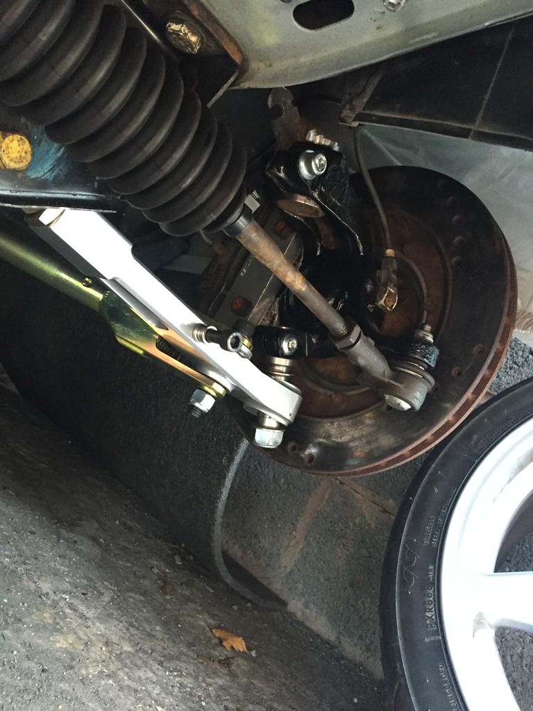
This is how mine sits jacked up. The pin is at a large angle but it's not bottomed out. I'll have to wait till the car is back together and driving till I can see what it's like. I sent mark a picture of it and he said that's how they sit and he has sold many sets with out issue so we will see.
Thats not right either, any large rebound and it will smash that arm to pieces.
Guys, you need to do it right, you are adding 'blingy' bits to your cars for the wrong reasons. That setup is designed to work a with a series of components and angles like them are dangerous, it will literally snap the arm.
This has nothing to do with adding bling and if you read my posts it looks like I am going full Wrc front which means matching hunbs and all the other bits.
The poster above has said he will see what it does when engine in and arb on, he is all about go not show (although likes proper presentation) and he will make sure it is right.
I appreciate your concern and input but I think the "adding bling bits for wrong reason" is a bit derogatory.
I added the adjustable tca s for one reason and that is to go bladed arb....the reason for this is that my standard arb from a Saph had to sit very low to pass under the 205 shell, this in turn meant low ground clearance but more than that it meant a huge sculpting in the proper exhaust made by nor tech to give clearance.
The bladed arb not only gives me adjustability but it gives the ground clearance that I needed and a much better exhaust route. I have said that I will make sure it it fully sorted one way or another and it will be, not for bling...the car must be perfect or it will not be finished in my eyes.
I am not driving the car again and waiting to move to the next stage once I have removed some camber to prove my theory that it is binding. At that point MK will receive another chunk of my savings
Toby what about the poss of raising the engine to see the driveshaft angle change not looked to see if it can go up by much.
Mark
Yes, that has been suggested. I will have another look but I don't know how much it will give me. I can space up the mounts to try it but the down pipe would need extending or the connector under v band as the pipe is very close to the front prop uj. Now the arb is out of the way we have some room to play on the pipe though.
If I can Nick a little bit on the engine then raise the ride height I might just get the driveshaft angle to a better position. The pin angle would be better and I can solve the rest of that I think.
Thanks for the input Mark. MK has suggested the same. If I go much higher then I fear the bell housing will tough the tunnel as it is pretty tight there too. I could re fab that but it would be a lot of work.
Thats not right either, any large rebound and it will smash that arm to pieces.
Guys, you need to do it right, you are adding 'blingy' bits to your cars for the wrong reasons. That setup is designed to work a with a series of components and angles like them are dangerous, it will literally snap the arm.
That's as far down as the arm can possibly go and the pin dose not touch the arm. As for how far up it go's I've no idea as the weight is not on the car. Also the toe caster and camber are not set. Mk who knows what he is talking about said he has sold lots of these kits over the years and not had any issues so we will see once it's up and running
And nothing has been added to mine as a blingy bit as you put it! It's there to be able to set the front up
That's as low as it can possibly go. As for how far up it go's I've no idea as the weight is not on the car. Also the toe caster and camber are not set. Mk who knows what he is talking about said he has sold lots of these kits over the years and not had any issues so we will see once it's up and running
And nothing has been added to mine as a blingy bit as you put it! It's there to be able to set the front up
On my car I can remove the pin and the hub droops lower which means the pin / ball joint is restricting the angle of the tca. I would prefer it to go full droop.
As my car stands now it is not level but it was before I put these on so it is binding on one side, I will measure the ride being and then undo the strut top, I. Am pretty sure the car will go back level as the pin goes straighter, I may be wrong.
I am sure this is specific to my car due to the different track width.
I want to be able to place the geometry anywhere so that compromises can be removed. I will get there.
I've not tried removing the pin. That picture above of mine is the strut at full extension. It dose put the pin at a large angle but it doesn't touch the arm at all. I'll have to wait and see how it sits as it moves up
I've not tried removing the pin. That picture above of mine is the strut at full extension. It dose put the pin at a large angle but it doesn't touch the arm at all. I'll have to wait and see how it sits as it moves up
Sounds like yours will be fine, mine is at that angle on the floor.
With the weight of the car I bet you will have a load of room and you will know soon enough as it sends a thump through the car when it bottoms out.
I went over some cats eyes and I thought I had not done up the wheel bolts.
If in doubt you can put a jack under the arm and move it up an inch or so and see what angle it goes to.
Last edited by Caddyshack; 29-06-2016 at 08:30 PM.
I could have comple new units made with bigger end angle.
That's what I meant, MK could make a pair of shorter arms with a different angle for you.
No doubt that's a pretty easy job for him and probably the easiest/cheapest option for you?
If you got the billet hubs, is the angle of pin entry different or in a different position as if not you will still have the same problem.
Yes, billet hubs have a flat bottom so the pin goes in quite upright through a billet steering arm. You then have the big Wrc bearings too. The Cossie hub has the pin location at an angle to start with.
MK kindly sent me pics to compare. He has offered to help me sort it one way or another and has really looked after me with pictures and advice.
Thanks to MK and Mark Shead for suggesting lifting the engine. I have been looking at this and I think I may have 10mm or more that I can play with so I will try this with some spacers under the engine mounts and if that works with no issues I will have some plates machined up to sit under there properly.
Thanks Gents.
I am going to put the WRC hubs on there, Billet steering arms and all the WRC bits that go with this and Mark is going to make me new brake adapters to suit so the pin angle will be solved with this.
If the driveshaft then still causes issues I will get MK to do a bespoke crossmember.
Yup full Wrc front end, at least I can get it set up by the experts as they will be able to put the wheels exactly where they want
I asked mark about mine again after reading the posts on here. He said mine sits fine and as he would expect jacked up or with no engine in it and I have nothing to worry about it will be fine.
I asked mark about mine again after reading the posts on here. He said mine sits fine and as he would expect jacked up or with no engine in it and I have nothing to worry about it will be fine.
No not yours mate another implying the parts are all wrong won't work correctly and just for show. Just good to know from the engineer who makes the parts that's rubbish
No not yours mate another implying the parts are all wrong won't work correctly and just for show. Just good to know from the engineer who makes the parts that's rubbish
Well in your pic the front driveshaft has already fallen out or is it off being chromed and diamond encrusted? Lol
Got the front hub off today so I can post the drive flange, calliper and disc to MK ready for the Wrc billet hubs etc.
I whipped off the front bumper whilst the car was on the ramp and offered up the airtec 100mm cooler, it fits really well after I cut a bit of room on the front panel for the mounting points to pass through, just need to fabricate the mounting points in the car. Now the boost tube points directly at the throttle body and I have enough room now for about 2-3 inches of ally rad to poke above the intercooler so that should get better airflow and now the airfilter can poke straight in to the front grille instead of hiding behind the front light so should be sucking in more nice cool air.
I saw 38degrees intake temp the other day so will be interesting to see if the inlet temps drop at all with the new cooler. Most of the time they were hovering around 20/25 degrees.
Some say, and I'm not sure of the science behind it, that 40 degrees is the best inlet temp. Something to do with fuel atomisation.
That's interesting, I always assumed colder the better but based on no science at all.
The thing is, there is science behind that theory. The colder air is the denser it is. The denser air is the more Oxygen is present.
I don't know whether it's true but there is the idea that if the fuel air mix is too cold that the fuel drops out of the ideal droplet size range for atomisation. This could completely be nonsense though.
I suspect Mr Shead will know. I will await his thoughts. Since the car was mapped I have a hart inlet and the bigger cooler so suspect the map will need a tweek
Today I stripped off the passenger side drive flange to send off to MK for the sleeve to fit the Wrc bearings and as I finished it early I thought I would carry on and fit the air tec 100mm cooler.
First job was to bend up some thick steel to make the mount and then internally weld on an end piece for strength. I drilled two holes to allow me to puddle weld it on to the car.
Then I had to cut some clearance holes for the cooler ear mounts to pass through the front panel.
Puddle welded on and tacked down the sides, I did a bit more to tidy it up but forgot to take a pic. When the engine comes out I will send the car to the body shop and have the engine bay fully repainted so this will be properly painted then.
I made two mounting holes hoping to use the rear as that way the 100mm cooler would sit slightly farther back from the rs500 position.
With the cooler mounted on the rearmost fitting I was able to experiment with the rubber matting that my friend dropped off, he owns a rubber factory and they make the masks for fighter pilots and the thrust ssc record attempt.
The rubber bolts to the cooler air scoop with one bolt and is then glued and riveted to the bumper so the bumper can still be removed easily. This now means air cannot pass around the cooler and must go through.
I will add some hook and loop so it seals in a straight line down the weld.
I will contact glue the rubber from<br/>Behind to form a tight seal on the bumper
This tab bolts on to the air Tec scoop and has now been trimmed to the exact shape.
 29-06-2016, 08:48 AM