GTR32 rebuild
 09-06-2006, 09:56 AM
#1
Wahay!! I've lost my Virginity!!
Thread Starter

Join Date: Oct 2005
Posts: 53
Likes: 0
Received 0 Likes
on
0 Posts
hi
i hope to edit this with more pics and more info,
hopefully this will be a start to finish engine removal, recon and refit, along the way i will try to do things as best i can with the cheapest parts i dare to fit...this is a budget build!!!
please be patient with the thread as i intend to edit this over a few months
hi
after buying a R32GTR the engine blew after 2 days on the way to the mechanics....i had a "det" noise and then lost a lot of compression on no:2 cylinder
i was fully aware of a tapping noise and i understand that this is a signature noise of detonation but this was soo loud i thought it was a gearbox mount..the car has a shortshifter on it but the seal had not been fitted allowing the noise to come from the gearbox area so even though i was on the way to a friends garage to have a look when it was on the lift i gave it about 3/4 throttle for a few secs and it dropped a cylinder
when i got to the garage we didnt bother checking the gearbox mounts lol but we did stand around shaking heads under the bonnet, we noticed that the fuel regulator hose had come away from the regulator.....this is a serious failure on a turbo car as the fuel regulator needs to increase the fuel pressure as boost rises, if it does not then the engine will run lean and detonation occurs
it may have been knocked off by one of us just before we noticed it so its not a definitive cause of this failure but its a good theory for the moment
upon checking the compression was 165-170psi across the board on the tester apart from no:2 which was 40psi down:apoke:
i havent the cash to pay for a rebuild and not many want to help on a project like this so i have done 99% of it alone
heres a pic of the car in my back garden awaiting rebuild

another as the dismantle process starts...chassis looks nice and stiff (jacked up on passenger front only)

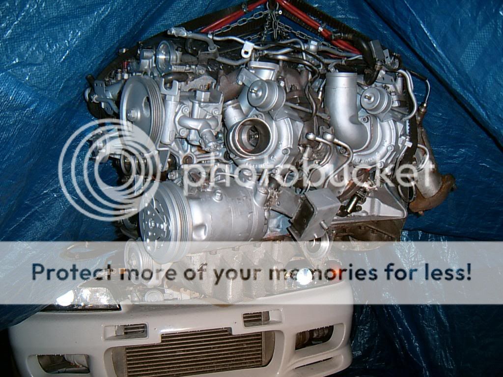
ive been fecking with cars for a long time now and in my previous cars i had honed down the engine strip down or removal process time to less than 3 hours but this car has a lot more stuff attached to it and after careful consideration it may prove easier to remove the engine rather than remove the inlet and exhaust manifolds in the car!, and really i need to remove the cylinder head to find out what i need to replace
some of the nuts on the inlet side seem so far away from access it may be impossible with conventional spanners and sockets and the exhaust side isnt much better, the odd pre-rounded off bolt here and there always being in the most inacessable of areas.....
the clutch is a real nasty paddle type so maybe it makes sence to change it during this engine work period anyway eh (well thats my excuse lol)
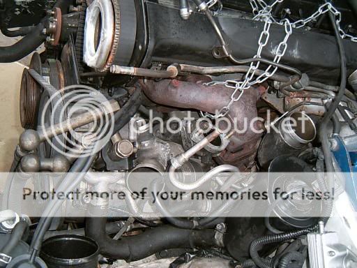
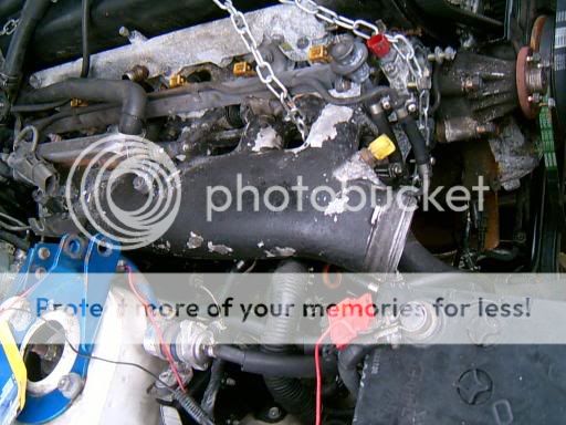
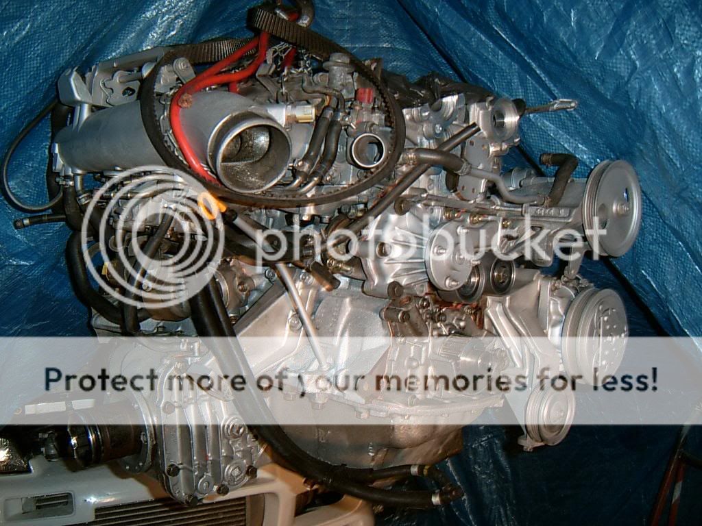
heres the exhaust side with the heat shields, inlet pipes and other stuff removed

i dont intend this to be a quick rebuild...at the mo is about 10 degrees outside and ill be doing all of the work my myself this time so most of the heavy stuff may just have to wait until warmer weather
as mentioned before its a pig of a car to work on but i tackled it like this
remove the inlet hoses from the bonnet area, remove rad and fan to get a bit of room to work in

the down pipe nuts, easier then they look to remove from under the car with a 14mm and extention

obviously it also needs to be disconnected from the cat also
i found a load of excess exhaust paste that had gone hard in the cat........now i know what that dam noise was lol

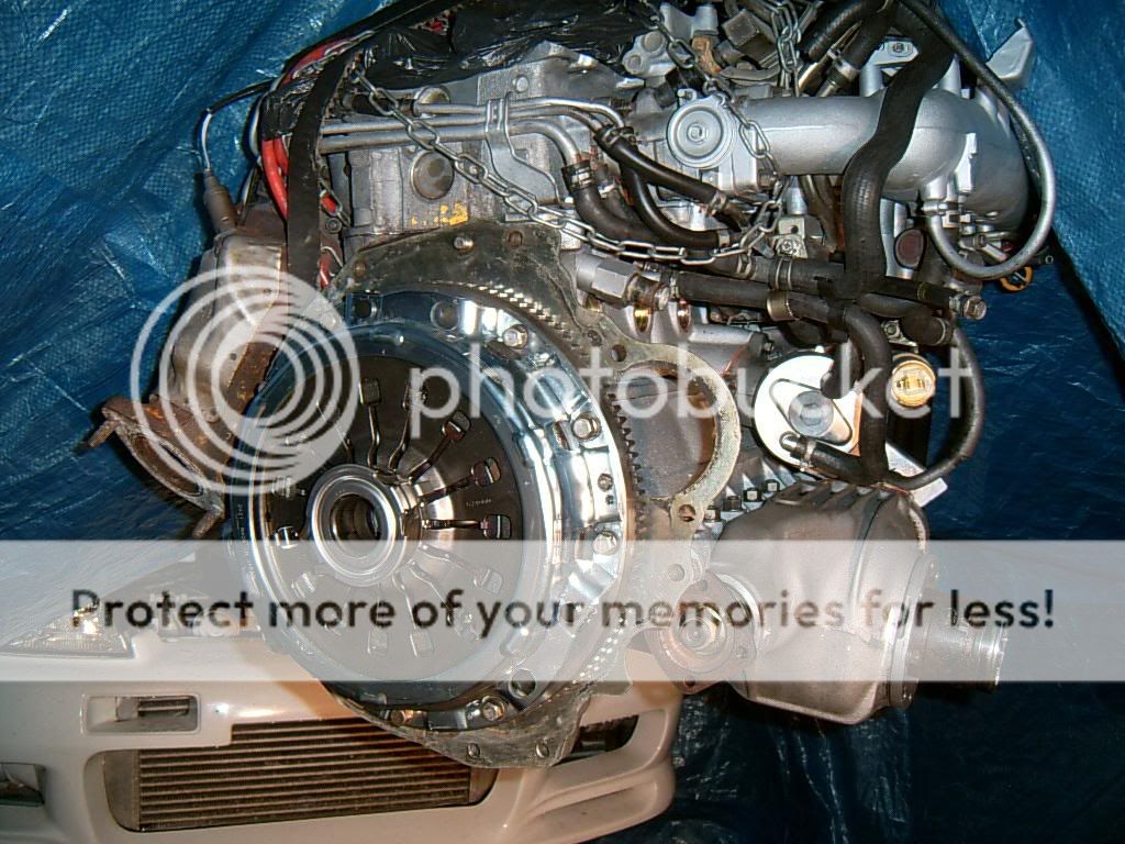
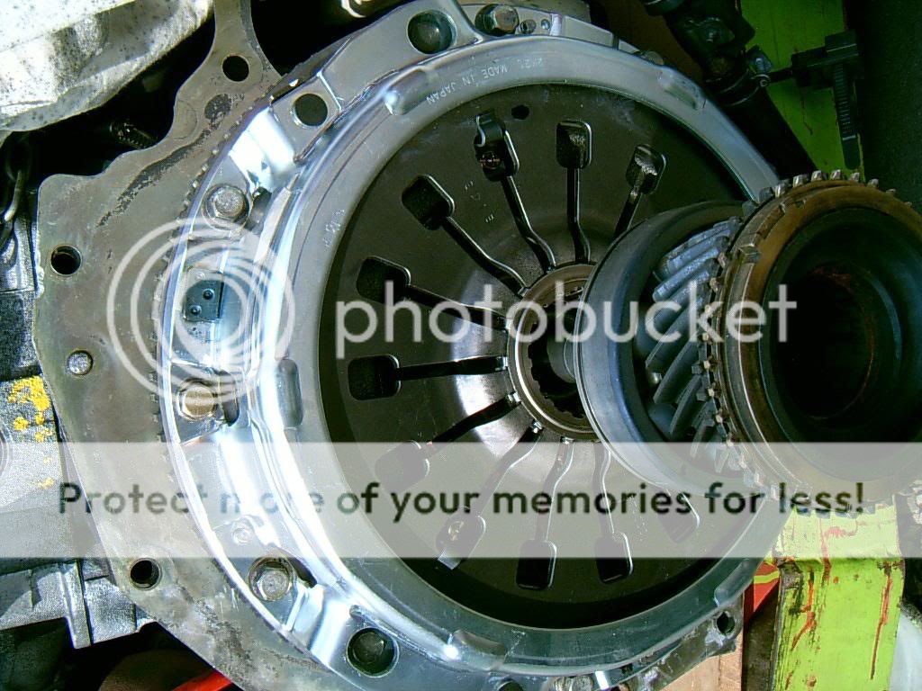
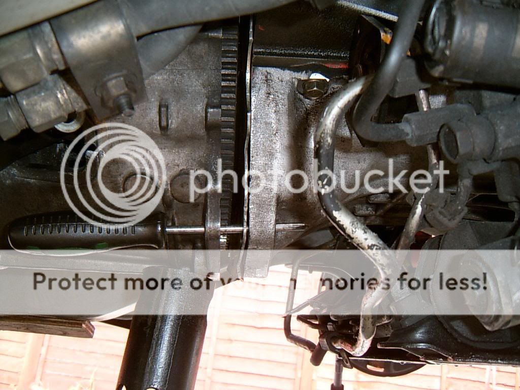
the clutch control arm needs to be removed on the pull type arrangement that i have on mine, you need to remove the slave cylinder and then prise a pin and circlip off from the end of the clutch arm inside the box, you gain acess through the hole the arm travels through
after the pin and circlip have been removed pull it away from the thrust bearing
the bottom bellhousing bolts are easy to get to but the top six bolts look almost impossible...if you remove the top and bottom driverside engine mount bolts and the bottom passenger side mount bolt you can jack the engine and then remove the driver side engine mount, the passenger side mount does not need to be removed to get the engine out of the bay
i hope to edit this with more pics and more info,
hopefully this will be a start to finish engine removal, recon and refit, along the way i will try to do things as best i can with the cheapest parts i dare to fit...this is a budget build!!!
please be patient with the thread as i intend to edit this over a few months
hi
after buying a R32GTR the engine blew after 2 days on the way to the mechanics....i had a "det" noise and then lost a lot of compression on no:2 cylinder
i was fully aware of a tapping noise and i understand that this is a signature noise of detonation but this was soo loud i thought it was a gearbox mount..the car has a shortshifter on it but the seal had not been fitted allowing the noise to come from the gearbox area so even though i was on the way to a friends garage to have a look when it was on the lift i gave it about 3/4 throttle for a few secs and it dropped a cylinder
when i got to the garage we didnt bother checking the gearbox mounts lol but we did stand around shaking heads under the bonnet, we noticed that the fuel regulator hose had come away from the regulator.....this is a serious failure on a turbo car as the fuel regulator needs to increase the fuel pressure as boost rises, if it does not then the engine will run lean and detonation occurs
it may have been knocked off by one of us just before we noticed it so its not a definitive cause of this failure but its a good theory for the moment
upon checking the compression was 165-170psi across the board on the tester apart from no:2 which was 40psi down:apoke:
i havent the cash to pay for a rebuild and not many want to help on a project like this so i have done 99% of it alone
heres a pic of the car in my back garden awaiting rebuild

another as the dismantle process starts...chassis looks nice and stiff (jacked up on passenger front only)

ive been fecking with cars for a long time now and in my previous cars i had honed down the engine strip down or removal process time to less than 3 hours but this car has a lot more stuff attached to it and after careful consideration it may prove easier to remove the engine rather than remove the inlet and exhaust manifolds in the car!, and really i need to remove the cylinder head to find out what i need to replace
some of the nuts on the inlet side seem so far away from access it may be impossible with conventional spanners and sockets and the exhaust side isnt much better, the odd pre-rounded off bolt here and there always being in the most inacessable of areas.....
the clutch is a real nasty paddle type so maybe it makes sence to change it during this engine work period anyway eh (well thats my excuse lol)
heres the exhaust side with the heat shields, inlet pipes and other stuff removed

i dont intend this to be a quick rebuild...at the mo is about 10 degrees outside and ill be doing all of the work my myself this time so most of the heavy stuff may just have to wait until warmer weather
as mentioned before its a pig of a car to work on but i tackled it like this
remove the inlet hoses from the bonnet area, remove rad and fan to get a bit of room to work in

the down pipe nuts, easier then they look to remove from under the car with a 14mm and extention

obviously it also needs to be disconnected from the cat also
i found a load of excess exhaust paste that had gone hard in the cat........now i know what that dam noise was lol

the clutch control arm needs to be removed on the pull type arrangement that i have on mine, you need to remove the slave cylinder and then prise a pin and circlip off from the end of the clutch arm inside the box, you gain acess through the hole the arm travels through
after the pin and circlip have been removed pull it away from the thrust bearing
the bottom bellhousing bolts are easy to get to but the top six bolts look almost impossible...if you remove the top and bottom driverside engine mount bolts and the bottom passenger side mount bolt you can jack the engine and then remove the driver side engine mount, the passenger side mount does not need to be removed to get the engine out of the bay
 09-06-2006, 09:56 AM
#2
Wahay!! I've lost my Virginity!!
Thread Starter
Join Date: Oct 2005
Posts: 53
Likes: 0
Received 0 Likes
on
0 Posts
when you drop the engine down onto the subframe you can get those bolts with a normal 14mm spanner from the bonnet side

the driveshafts are held in by circlips and in theory they just need a jolt and they will come free if you have removed the hub to allow movement, i couldnt do this on the driver side though even after about an hour of abuse, tried to release it from inside the diff housing to no avail so i split the shaft fromm the engine side joint, it didnt make engine removal any harder with it still attached


the passenger side has a very long driveshaft and it also needs to be unbolted from the engine before removal, the driveshaft castlenuts are a 36mm BTW
i left it to almost last to remove the power steering hoses..
the engine should come free as soon as you try to "wiggle" it off the input shaft, i didnt put a jack under the gearbox as it seemed very secuore by itself
once thats all done just lift the engine as much as you can whilst keeping an eye on any wires still attached, the higher the engine is at this point the easier it is to remove the knock sensors etc

sounds straightforward but that took me the best part of 20 hours in a typical english febuary 5 degree wether

hopefully i can have this stripped and rebuilt within a month!?
09-06-2006, 09:57 AM
#3
Wahay!! I've lost my Virginity!!
Thread Starter
Join Date: Oct 2005
Posts: 53
Likes: 0
Received 0 Likes
on
0 Posts
the strip down process is pretty normal really, i wont go into that as this guide is for the experianced mechanic (although a beginners guide to skyline engine overhaul process)
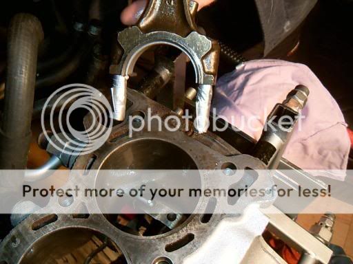
upon removal of the head the valves in cylinder two showed no signs of damage...i filled it with water but none seeped through (water may not be thin enough for some but its thin enough for 40psi drop i believe eh)
the head gaskett seemed ok too
upon removal of the piston it also seemed fine...as i started to clean it i saw det marks on the "flats" of the piston
cleaning a bit more on the ringlands gave a nasty surprise!!, a lump of no:2 ringland came off in my hand and i then saw two cracks in the ringland above it!

just sittting there waiting to jump out eh lol,the detonation couldnt break the top of the piston but the shockwave the detonation made traveled through the piston and cracked it where it was weakest....a bit like the "din mak" that jean-claude van damme done in the film bloodsport lol!
the others have tiny cracks here and there..wouldnt have thought they were cracks until i saw no:2 piston so if you are doing a rebuild yourself changing the pistons or having them xrayed would be a very good idea if you have any signs of detonation on the flats
so...a set of forged pistons is on the cards and this is where the skyline tuning parts prices come into play............you can easy pay �1200 for HKS pistons and near that price for most makes that uk tuners stock
some uk tuners charge �3-5000 for a basic rebuild compared to �700-�1200 for your average 6 cylinder engine
the prices of OE parts isnt too bad...�50 for bearings, �260 for a slightly uprated clutch, gasket kit �140 so why the massive prices?
apart from the "hassle" involved with a GTR rebuild there seems to be a serious lack of infomation on the net (or anywhere else!) about the cars/engines, and from what ive read most rebuilds end in enginge failure even when done by some tuning companys...
http://www.gtr.co.uk/forum/upload/sh...engine+failure
in fact my engine had 6/6/05 on the sump and rocker indicating that the engine had just been replaced....i presume due to engine failure?....this engine only lasted a few hundred miles before it blew for one reason or another so the chances of this "poverty" rebuild going smoothly is low to nil maybe
so anyway..the first and longest job of the rebuild should be the clean down, if you take the bits off and get them as clean as possible before starting any engine work the whole rebuild will be a far less messy operation
heres the inlet and exhaust manifolds as they were
i just gave them a degrease with some gunk, jetted them off and then put them in a friends sandblaster
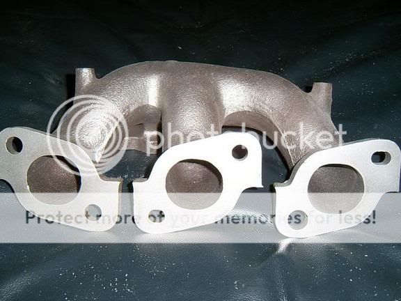
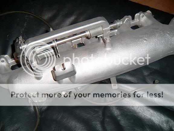
i done that to pretty much all of the parts i could as the engine was very corroded, even the turbos
upon removal of the head the valves in cylinder two showed no signs of damage...i filled it with water but none seeped through (water may not be thin enough for some but its thin enough for 40psi drop i believe eh)
the head gaskett seemed ok too
upon removal of the piston it also seemed fine...as i started to clean it i saw det marks on the "flats" of the piston
cleaning a bit more on the ringlands gave a nasty surprise!!, a lump of no:2 ringland came off in my hand and i then saw two cracks in the ringland above it!
just sittting there waiting to jump out eh lol,the detonation couldnt break the top of the piston but the shockwave the detonation made traveled through the piston and cracked it where it was weakest....a bit like the "din mak" that jean-claude van damme done in the film bloodsport lol!
the others have tiny cracks here and there..wouldnt have thought they were cracks until i saw no:2 piston so if you are doing a rebuild yourself changing the pistons or having them xrayed would be a very good idea if you have any signs of detonation on the flats
so...a set of forged pistons is on the cards and this is where the skyline tuning parts prices come into play............you can easy pay �1200 for HKS pistons and near that price for most makes that uk tuners stock
some uk tuners charge �3-5000 for a basic rebuild compared to �700-�1200 for your average 6 cylinder engine
the prices of OE parts isnt too bad...�50 for bearings, �260 for a slightly uprated clutch, gasket kit �140 so why the massive prices?
apart from the "hassle" involved with a GTR rebuild there seems to be a serious lack of infomation on the net (or anywhere else!) about the cars/engines, and from what ive read most rebuilds end in enginge failure even when done by some tuning companys...
http://www.gtr.co.uk/forum/upload/sh...engine+failure
in fact my engine had 6/6/05 on the sump and rocker indicating that the engine had just been replaced....i presume due to engine failure?....this engine only lasted a few hundred miles before it blew for one reason or another so the chances of this "poverty" rebuild going smoothly is low to nil maybe
so anyway..the first and longest job of the rebuild should be the clean down, if you take the bits off and get them as clean as possible before starting any engine work the whole rebuild will be a far less messy operation
heres the inlet and exhaust manifolds as they were
i just gave them a degrease with some gunk, jetted them off and then put them in a friends sandblaster
i done that to pretty much all of the parts i could as the engine was very corroded, even the turbos
09-06-2006, 09:58 AM
#4
Wahay!! I've lost my Virginity!!
Thread Starter
Join Date: Oct 2005
Posts: 53
Likes: 0
Received 0 Likes
on
0 Posts
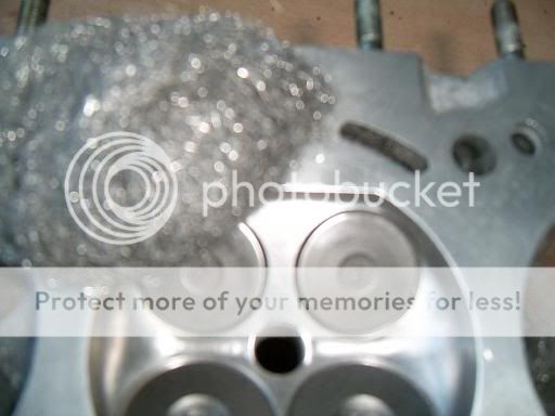
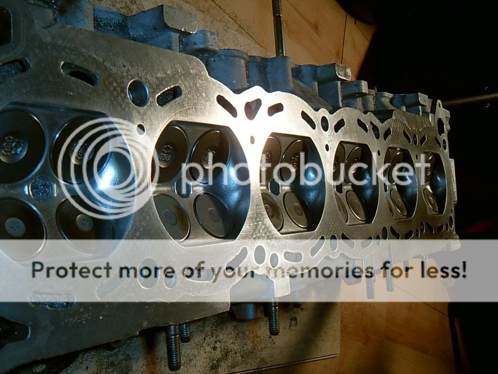
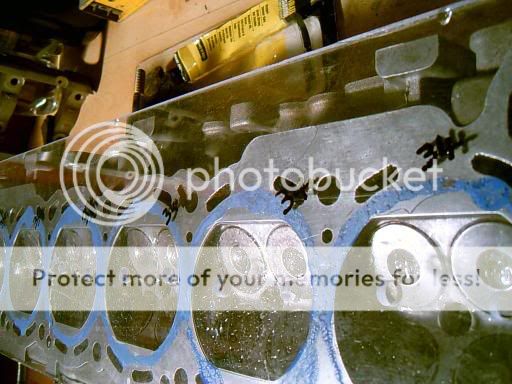
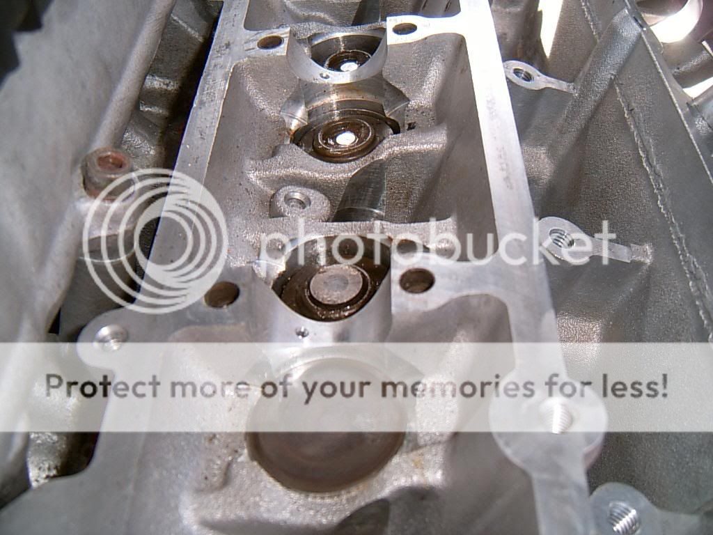
to clean the head i used oven cleaner as per instructions on the carbonised parts of the head and jetted off, i then used fine grade wet and dry (wet) followed by fine wire wool to get a polish...this isnt just done from a cleaning point of view, it makes sure there is no sharp edges/hotspots on the combustion surface and will reduce the chances of detonation in future, the flat part of the combustion face (the bits that stop the head part of the cylinder being round) should also be rounded off slightly to avoid det...the inlet side is more prone to det than the exhaust side
so before clean down we have something like this
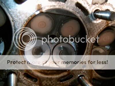
combustion face, oven cleaner first then jetter should get something like this
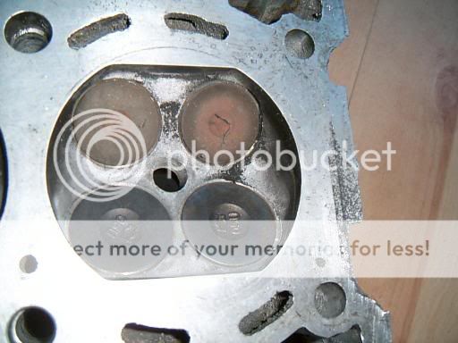
same bit but rubbed with fine grade wet and dry (wet) for about 45mins..maybe less
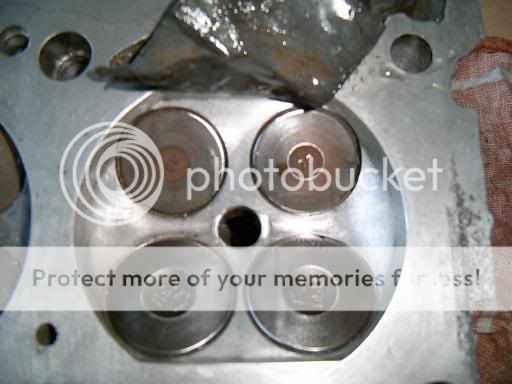
same bit, polished with fine wire wool for about 30mins
i cleaned the mating surface in the same way...didnt take too much time doing this as i have not yet checked the volume of the combustion areas on the head so it may need a skim if its off but we will come to that shortly, make sure you use a straight edge on top of your cleaning medium to make sure you are removing any material in a uniform manner
doing this polishing is a long process but it really does have great results
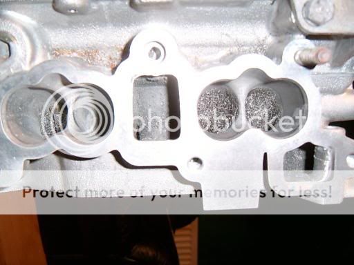
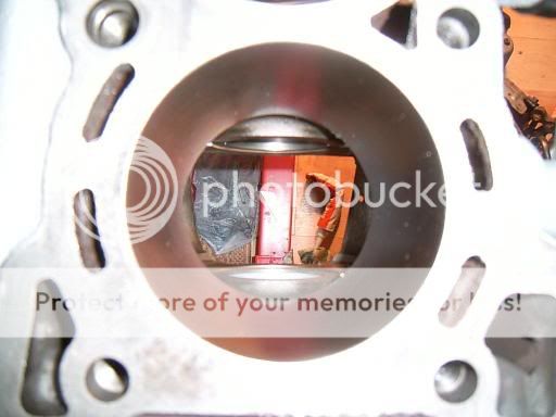
now heres an exhaust port as stock

here is one with the bump removed
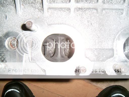
i used a dremmel with a sandpaper end, then wet and dry followed by wire wool
the inlet side just wanted smoothing off really
now we can check the volume of the cylinder part of the head, i used some perspex, some sealant and a 100ml syringe
you will need to drill two holes for each cylinder..one so you can fill the void with water and one to let the air escape
put perspex onto head, mark out two holes for each cylinder and then drill the holes
then apply sealant to the perspex/head and weight it down for 45mins or so, aftrer that fill a 100ml syringe up and fill each cylinder with parrafin, you can use water but if it does get past the valve it can corrode the valve seat..
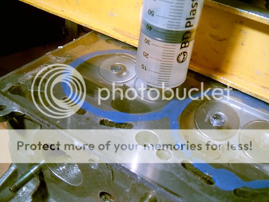
you may want to check for leaks as one of mine was letting by at the sparkplug which gave some very confusing results lol
remember to keep a record of the volumes...
i got 66ml accross the board so no problems there (34ml left in the syringe)
so before clean down we have something like this
combustion face, oven cleaner first then jetter should get something like this
same bit but rubbed with fine grade wet and dry (wet) for about 45mins..maybe less
same bit, polished with fine wire wool for about 30mins
i cleaned the mating surface in the same way...didnt take too much time doing this as i have not yet checked the volume of the combustion areas on the head so it may need a skim if its off but we will come to that shortly, make sure you use a straight edge on top of your cleaning medium to make sure you are removing any material in a uniform manner
doing this polishing is a long process but it really does have great results
now heres an exhaust port as stock
here is one with the bump removed
i used a dremmel with a sandpaper end, then wet and dry followed by wire wool
the inlet side just wanted smoothing off really
now we can check the volume of the cylinder part of the head, i used some perspex, some sealant and a 100ml syringe
you will need to drill two holes for each cylinder..one so you can fill the void with water and one to let the air escape
put perspex onto head, mark out two holes for each cylinder and then drill the holes
then apply sealant to the perspex/head and weight it down for 45mins or so, aftrer that fill a 100ml syringe up and fill each cylinder with parrafin, you can use water but if it does get past the valve it can corrode the valve seat..
you may want to check for leaks as one of mine was letting by at the sparkplug which gave some very confusing results lol
remember to keep a record of the volumes...
i got 66ml accross the board so no problems there (34ml left in the syringe)
09-06-2006, 09:58 AM
#5
Wahay!! I've lost my Virginity!!
Thread Starter
Join Date: Oct 2005
Posts: 53
Likes: 0
Received 0 Likes
on
0 Posts
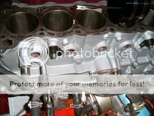
with the head now prepped and ready for lapping the parts have arrived to start the block
as mentioned previously the pistons were all either damaged or had suspected fractures on the ringlands...to replace these with stock items would cost �70 each from nissan but TBH they aint great pistons so i have gone with a larger bore with a set of JE forged items i bought from the american ebay site, worked out about �470 with shipping and customs tax
going 1mm oversize works out to be 2628cc (stock being 2568cc), this will not increase power by any noticable margin
the engine needs a good jetting out after any work like this, making sure no swarf has found a corner to hide in, all of the oilways and water ports blown through with the coreplugs removed for 30mins or so followed by some compressed air to dry it off is a must, dont want to allow any corrosion to get into the oilways, finish off with some WD40 on the oilports, journals and mating surfaces
i gave it a coat of silver high temp paint whilst it was outside and dry
moving on to the pistons....i weighed and bagged every piston and recorded the weight, i done the same with the pins and the rods with the old bearings removed
i found about 1 gram difference on the new JE's and about 4 gram on the rods, i am not going to balance the rods or pistons but i did do some basic blueprinting which is setting the heaviest piston with the lighest rod and so on
i took a record of the stock piston weight vs the new ones for no other reason than curisoty..
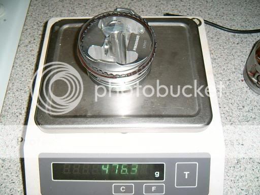
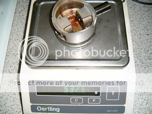
nice set of scales eh and perfect for this application....i got hold of this during the time i was made redundant from a closeing down sugar factory
the stock rods averaged out at about 640g IIRC
there are some sharp edges on the pistons that id prefer removed, i used some fine wet and dry to round off all of the sharp edges on the face of the piston, basicially its minimising the amount of hotspots which will go some way to deter detonation
i went with the recommended 4 thou bore clearance and ring clearances for "street car turbo/nitrous", the clearances have to be worked out by inch of bore, in this case its 87mm so thats 3.4 inches roughly, this does not apply to the oil control ring cluster though!
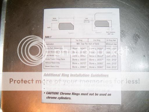
TBH i would prefer to see a more reasonable description of the application, there are too many variables on a turbo/nitrous engine to just throw it all into one part of the scale IMHO
on a previous engine i used the max clearance for turbo/nitrous on the bore and also on the rings........that was an engine that was designed to last ten thousand miles and no more so remember that if you want bigger cleances, lifespan will decrease at an unbelieveable rate the bigger your clearances are as they only allow good sealing of the rings at very high temps (which is what you would want on a 10 second drag car but this is a road car...)
so i have gone with a clearance of 17-18 thou on the top ring, 23 thou on the middle ring and the stock gapping on the oil ring which is ok provided its over 15 thou
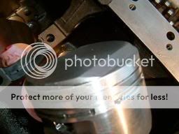
the rings are file fit so its just a matter of filing gently on one side of the ring until you can fit the feeler guage through the gap in the ring with just a tiny bit of resistance when it is installed in the bore for your desired clearance
i always chase the ring up and down the bore clecking the clearance after i have finished filing the ring, if the clearance on your ring increases or discreases as you do this the bore has a "taper" to it
the JE pistons seem to have a lot of failures where the pin (or circlip) jumps ship and allows the gundgeon pin to slide out, there isnt any info supplied with the piston set as to how to fit them but after looking at their site and speaking to people on forums the general method is to place the open ends into the groove facing away from the face of the piston and push in with your fingers, it shouldnt be hard to push them in if you are using the right technique...they just slide in real easy and hopefully make a nice click when they seat to let you know they are home, i still rotate them a few times just to make sure though as you really dont want to make a mistake here
with any rod/gudgeon pin there should be roughly 1 thou clearance...its not easy to measure this without specialised mics but if you oil and then place the gudgeon pin into the rod it should slowly glide through *slowly under gravity alone
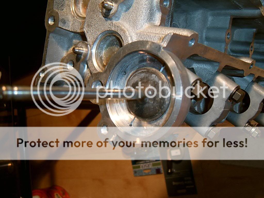
although there was no crank failure on my engine i still wanted to get the crank checked over, it came back "all ok" but i had the jounals polished up whilst it was there
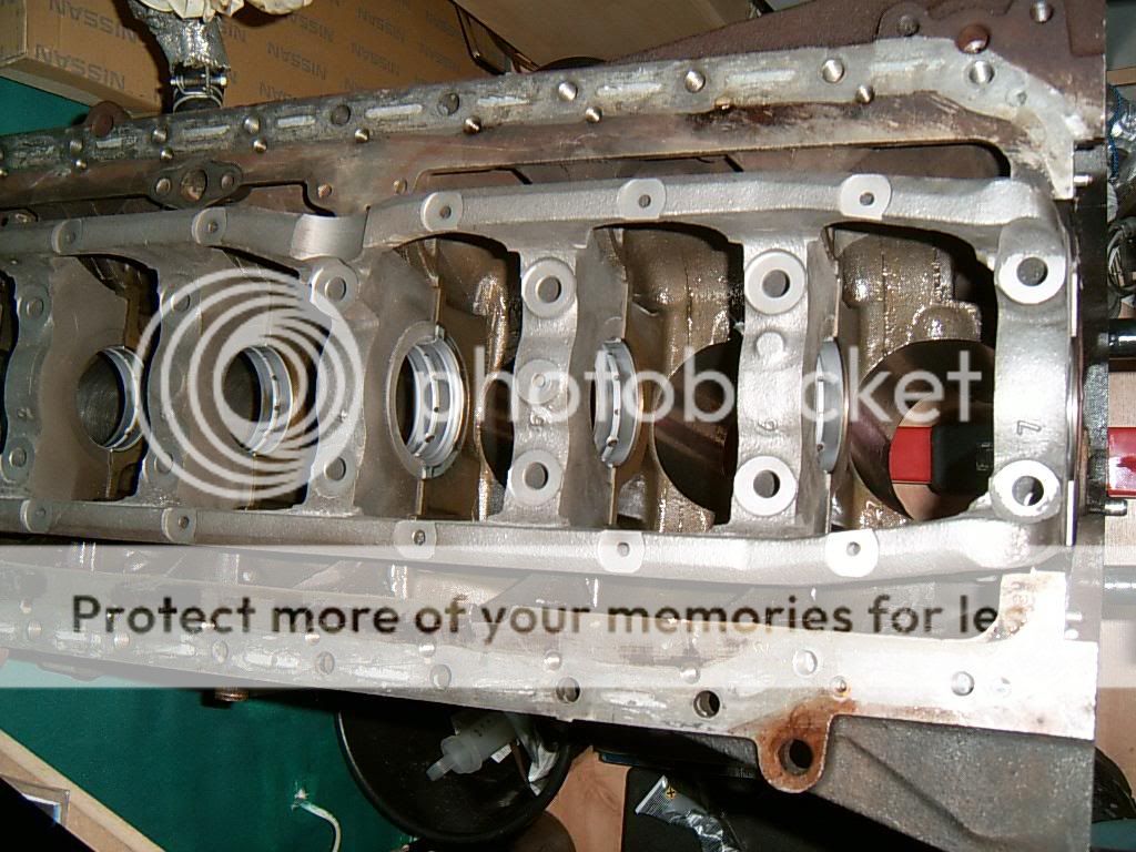
the bearings are a bit tricky on these engines...normally its just a case of ordering a new stock set but these are all graded
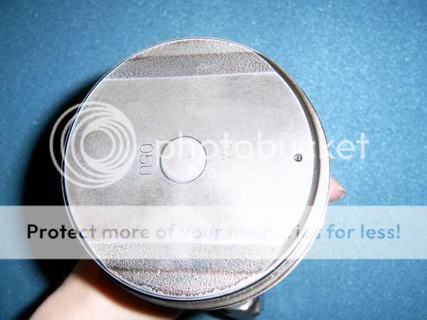
there is a beraring grade stamped into the sump face for each main bearing and another for the cranks mains jounals, these numbers are listed on the flywheel end of the crank
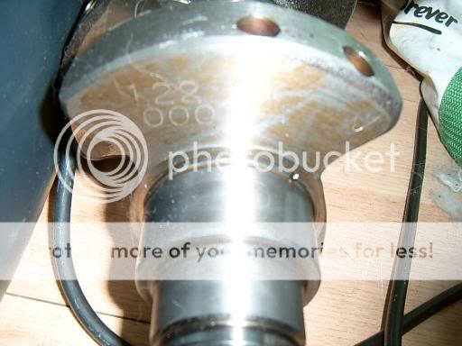

top-mains journals
bottom-rod journals
left to right nos 1-7/1-6
you add the numbers on the block to the numbers on the crank and thats the grade of bearing you need
same thing with the rods and the pistons (obviously the piston grade does not apply if you have a rebore)
also remember that cylinder 4 mains has the thrust bearing bit on it and you will need to mention that when you order
these bearing grades should still only be used as a guide, the bearings will still require checking with "plastigauge" if we are to be sure that clearances are correct and that the crank journals are not eliptical, it was given the "ok" by the rebore company but ill trust my own measurements only!, the crank is SO important you cant just take it for granted......double checking here will prevent the engine coming back out again in a few weeks time
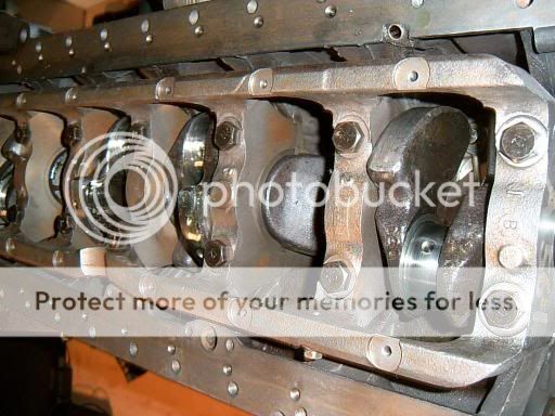
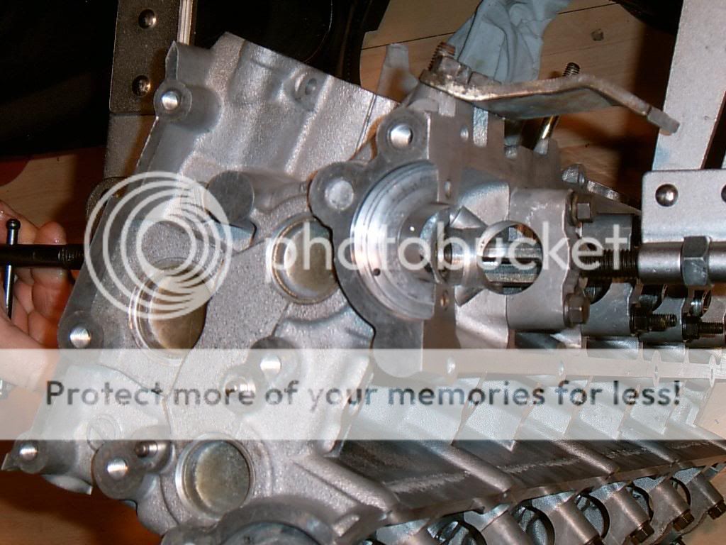
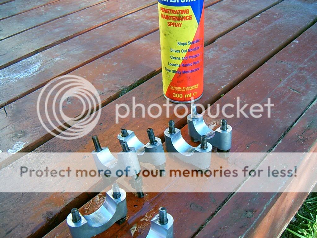
after installing the mains bearings (prior to checking) we started to install the oil squirters..pretty cool items by all accounts and its a wonder why they are not fitted to all engines, they have an oilway and valve inside the bolt so make sure you fit the right ones in lol, the piston is also supplied with oil by the rod
one of mine had been damaged somehow, it wasnt until it was positioned along with the others that we noticed the bend...and then the crack on the shaft
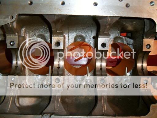
cant be too careful eh:nonono:
i doubt it would have led to an immediate engine failure as the squirter is pressure dependant....if oil pressure drops under 3 bar (guess) the oil squirters are shut down, it may have led to failure at full throttle with lots of heat in the piston though
also from the above picture you should be able to see the block "cast lines"...these are basicially strees points that we could removed if we wished....this would be a very useful mod on a block that is on the brink of its power level but on this engine 500bhp would take you nowhere near that stage so i have mostly left them alone but i did take the shap edge off them....just a tickle with the dremmel to radius the stress point
there is more infomation on this subject on www.max-boost.co.uk under "advanced"
as mentioned previously the pistons were all either damaged or had suspected fractures on the ringlands...to replace these with stock items would cost �70 each from nissan but TBH they aint great pistons so i have gone with a larger bore with a set of JE forged items i bought from the american ebay site, worked out about �470 with shipping and customs tax
going 1mm oversize works out to be 2628cc (stock being 2568cc), this will not increase power by any noticable margin
the engine needs a good jetting out after any work like this, making sure no swarf has found a corner to hide in, all of the oilways and water ports blown through with the coreplugs removed for 30mins or so followed by some compressed air to dry it off is a must, dont want to allow any corrosion to get into the oilways, finish off with some WD40 on the oilports, journals and mating surfaces
i gave it a coat of silver high temp paint whilst it was outside and dry
moving on to the pistons....i weighed and bagged every piston and recorded the weight, i done the same with the pins and the rods with the old bearings removed
i found about 1 gram difference on the new JE's and about 4 gram on the rods, i am not going to balance the rods or pistons but i did do some basic blueprinting which is setting the heaviest piston with the lighest rod and so on
i took a record of the stock piston weight vs the new ones for no other reason than curisoty..
nice set of scales eh and perfect for this application....i got hold of this during the time i was made redundant from a closeing down sugar factory
the stock rods averaged out at about 640g IIRC
there are some sharp edges on the pistons that id prefer removed, i used some fine wet and dry to round off all of the sharp edges on the face of the piston, basicially its minimising the amount of hotspots which will go some way to deter detonation
i went with the recommended 4 thou bore clearance and ring clearances for "street car turbo/nitrous", the clearances have to be worked out by inch of bore, in this case its 87mm so thats 3.4 inches roughly, this does not apply to the oil control ring cluster though!
TBH i would prefer to see a more reasonable description of the application, there are too many variables on a turbo/nitrous engine to just throw it all into one part of the scale IMHO
on a previous engine i used the max clearance for turbo/nitrous on the bore and also on the rings........that was an engine that was designed to last ten thousand miles and no more so remember that if you want bigger cleances, lifespan will decrease at an unbelieveable rate the bigger your clearances are as they only allow good sealing of the rings at very high temps (which is what you would want on a 10 second drag car but this is a road car...)
so i have gone with a clearance of 17-18 thou on the top ring, 23 thou on the middle ring and the stock gapping on the oil ring which is ok provided its over 15 thou
the rings are file fit so its just a matter of filing gently on one side of the ring until you can fit the feeler guage through the gap in the ring with just a tiny bit of resistance when it is installed in the bore for your desired clearance
i always chase the ring up and down the bore clecking the clearance after i have finished filing the ring, if the clearance on your ring increases or discreases as you do this the bore has a "taper" to it
the JE pistons seem to have a lot of failures where the pin (or circlip) jumps ship and allows the gundgeon pin to slide out, there isnt any info supplied with the piston set as to how to fit them but after looking at their site and speaking to people on forums the general method is to place the open ends into the groove facing away from the face of the piston and push in with your fingers, it shouldnt be hard to push them in if you are using the right technique...they just slide in real easy and hopefully make a nice click when they seat to let you know they are home, i still rotate them a few times just to make sure though as you really dont want to make a mistake here
with any rod/gudgeon pin there should be roughly 1 thou clearance...its not easy to measure this without specialised mics but if you oil and then place the gudgeon pin into the rod it should slowly glide through *slowly under gravity alone
although there was no crank failure on my engine i still wanted to get the crank checked over, it came back "all ok" but i had the jounals polished up whilst it was there
the bearings are a bit tricky on these engines...normally its just a case of ordering a new stock set but these are all graded
there is a beraring grade stamped into the sump face for each main bearing and another for the cranks mains jounals, these numbers are listed on the flywheel end of the crank
top-mains journals
bottom-rod journals
left to right nos 1-7/1-6
you add the numbers on the block to the numbers on the crank and thats the grade of bearing you need
same thing with the rods and the pistons (obviously the piston grade does not apply if you have a rebore)
also remember that cylinder 4 mains has the thrust bearing bit on it and you will need to mention that when you order
these bearing grades should still only be used as a guide, the bearings will still require checking with "plastigauge" if we are to be sure that clearances are correct and that the crank journals are not eliptical, it was given the "ok" by the rebore company but ill trust my own measurements only!, the crank is SO important you cant just take it for granted......double checking here will prevent the engine coming back out again in a few weeks time
after installing the mains bearings (prior to checking) we started to install the oil squirters..pretty cool items by all accounts and its a wonder why they are not fitted to all engines, they have an oilway and valve inside the bolt so make sure you fit the right ones in lol, the piston is also supplied with oil by the rod
one of mine had been damaged somehow, it wasnt until it was positioned along with the others that we noticed the bend...and then the crack on the shaft
cant be too careful eh:nonono:
i doubt it would have led to an immediate engine failure as the squirter is pressure dependant....if oil pressure drops under 3 bar (guess) the oil squirters are shut down, it may have led to failure at full throttle with lots of heat in the piston though
also from the above picture you should be able to see the block "cast lines"...these are basicially strees points that we could removed if we wished....this would be a very useful mod on a block that is on the brink of its power level but on this engine 500bhp would take you nowhere near that stage so i have mostly left them alone but i did take the shap edge off them....just a tickle with the dremmel to radius the stress point
there is more infomation on this subject on www.max-boost.co.uk under "advanced"
09-06-2006, 09:59 AM
#6
Wahay!! I've lost my Virginity!!
Thread Starter
Join Date: Oct 2005
Posts: 53
Likes: 0
Received 0 Likes
on
0 Posts
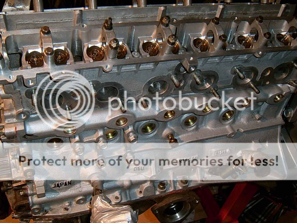
the coreplugs should be renewed at this point..they are cheap and can only really be all renewed when the engine is out...just knock the sifdeways in their bore, remove with pliers and then use the least bent old coreplug as a drift to insert the new ones with
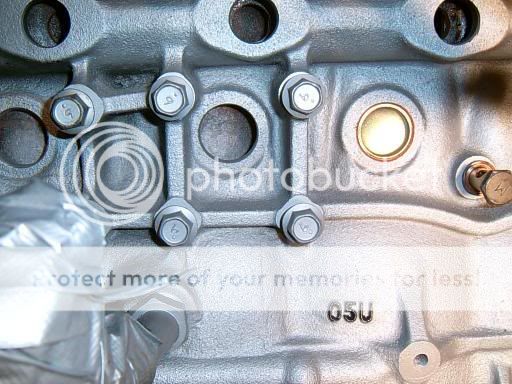
the bearing grades on the mains, crank and rods have been noted and ordered to spec, i had the crank checked whilst i was having the block bored but i would still like to check it with plastigauge
the bearings are fitted to the block, mains and rods but without oil!
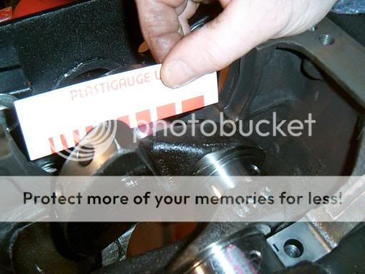
you want to cut a slither of the stuff so its slightly shorter than the jounal itself, do this to all of the mains journals on the crank with the crank placed in the engine awaiting the girdle
now fit the girdle with the plastigauge in situ being careful not to knock it off, torque up the bolts in the correct fashion and then dis-assemble it all again to measure and then remove the plastigauge
measurement is real easy with the bit of card they supply, you just match the size of the "splat" it makes on the crank with a splat on the card lol
the stock clearance is just under 2 thou, max clearance is 3.5 thou, all of mine came up at around 2.0-2.1 so well within clearance

mains bearings cleaned and oiled ready for the crank to be finially fitted
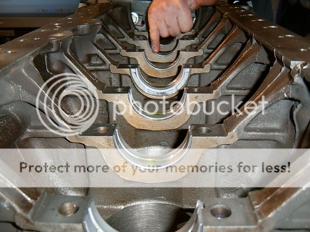
mains offered up to block just prior to crank install
crank and mains fitted
top view
the bearing grades on the mains, crank and rods have been noted and ordered to spec, i had the crank checked whilst i was having the block bored but i would still like to check it with plastigauge
the bearings are fitted to the block, mains and rods but without oil!
you want to cut a slither of the stuff so its slightly shorter than the jounal itself, do this to all of the mains journals on the crank with the crank placed in the engine awaiting the girdle
now fit the girdle with the plastigauge in situ being careful not to knock it off, torque up the bolts in the correct fashion and then dis-assemble it all again to measure and then remove the plastigauge
measurement is real easy with the bit of card they supply, you just match the size of the "splat" it makes on the crank with a splat on the card lol
the stock clearance is just under 2 thou, max clearance is 3.5 thou, all of mine came up at around 2.0-2.1 so well within clearance
mains bearings cleaned and oiled ready for the crank to be finially fitted
mains offered up to block just prior to crank install
crank and mains fitted
top view
09-06-2006, 09:59 AM
#7
Wahay!! I've lost my Virginity!!
Thread Starter
Join Date: Oct 2005
Posts: 53
Likes: 0
Received 0 Likes
on
0 Posts
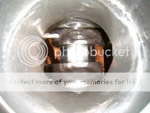
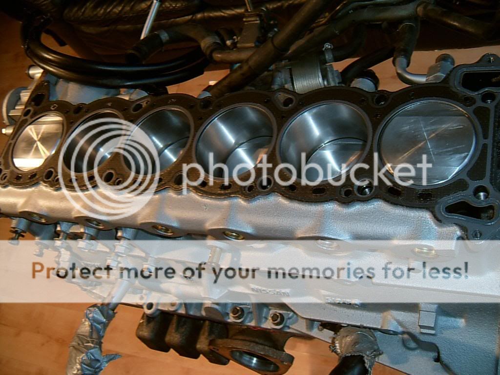
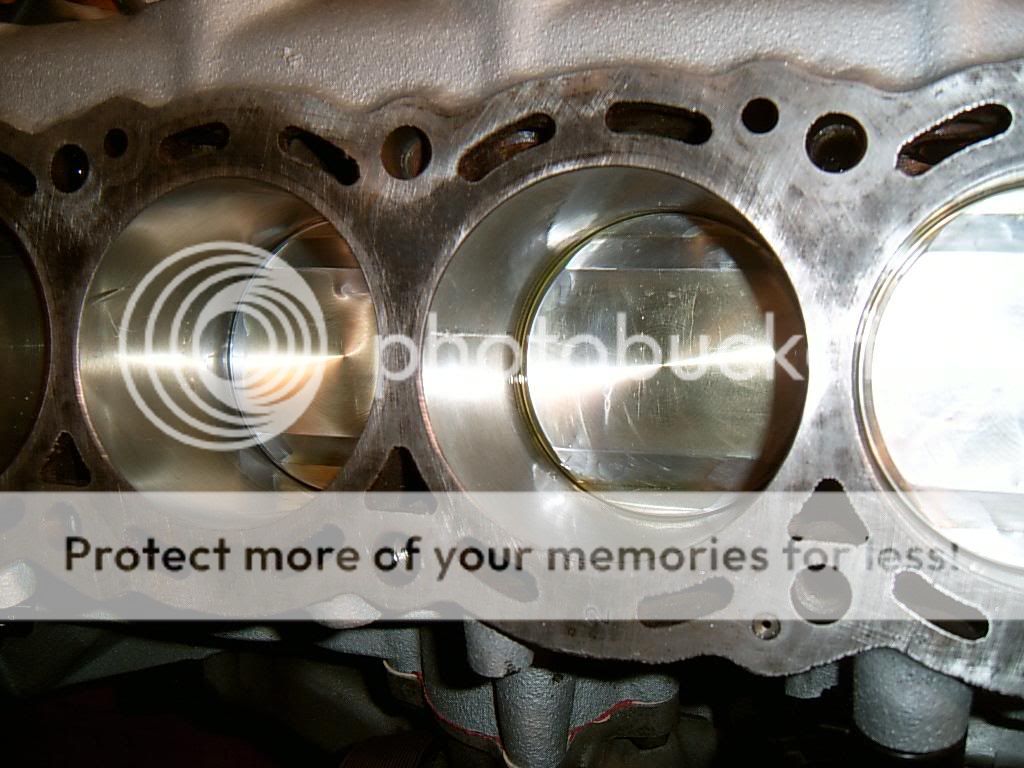
all coming together now!, the piston rings have already been cut to spec and they have been fitted to the rods already too so its just a case of taking them with their piston and oiling them up to help slide them in to the cylinder
before we fitted the rod/piston we placed duck tape on the studs to prevent assembly marks to the crank journal
bolt up the rod to the crank to the correct torque and repeat 6 times

fit the splashplates, oil pickup, oil pump and the flywheel side crank cover before fitting the sump
heat the timing pulley up in a saucepan of water before fitting to help it go on and make sure the washers are round the right way!, round one to block, then timing pulley with groove to block, then curved washer with the bowl facing away from the engine before fitting the pulley
pump and timing pulley fitted
bottom end rebuild complete
the head is now back on the agenda for the next stage
before we fitted the rod/piston we placed duck tape on the studs to prevent assembly marks to the crank journal
bolt up the rod to the crank to the correct torque and repeat 6 times
fit the splashplates, oil pickup, oil pump and the flywheel side crank cover before fitting the sump
heat the timing pulley up in a saucepan of water before fitting to help it go on and make sure the washers are round the right way!, round one to block, then timing pulley with groove to block, then curved washer with the bowl facing away from the engine before fitting the pulley
pump and timing pulley fitted
bottom end rebuild complete
the head is now back on the agenda for the next stage
Trending Topics
09-06-2006, 09:59 AM
#8
Wahay!! I've lost my Virginity!!
Thread Starter
Join Date: Oct 2005
Posts: 53
Likes: 0
Received 0 Likes
on
0 Posts
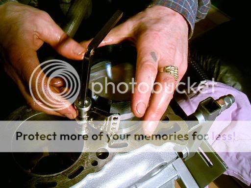
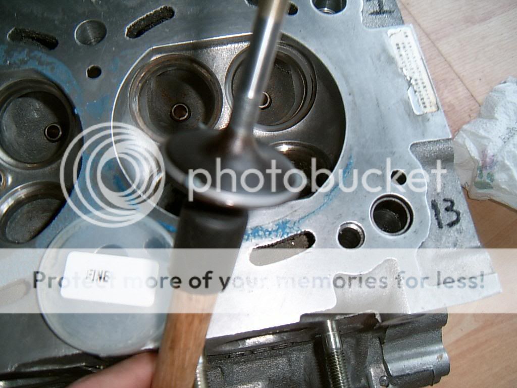
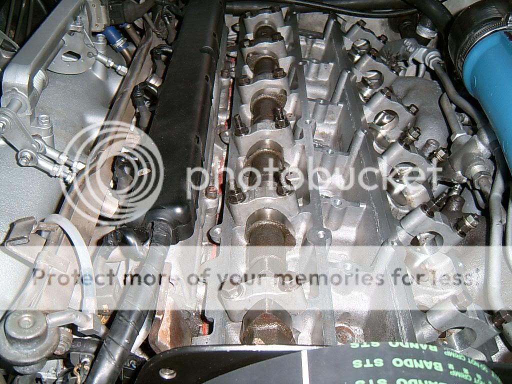
so the last time we saw the head it was clean and measured, the next stage is to "cut" the valves in and replace the seals
if you have not done this before you will need these
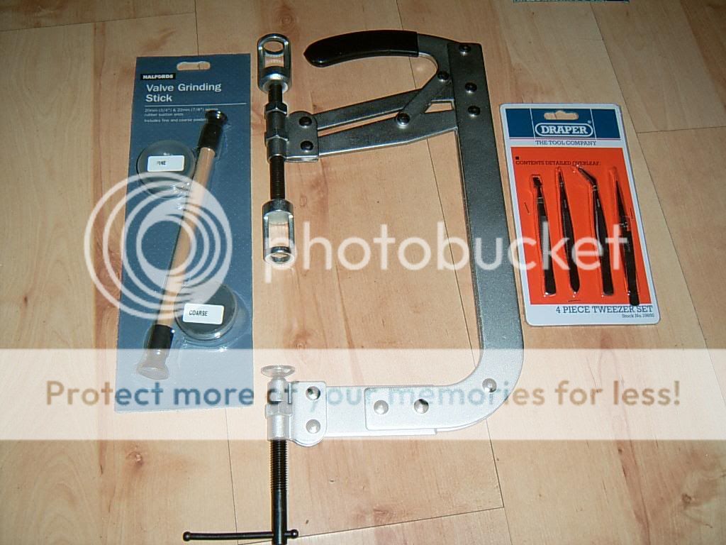
the idea is to clamp the valve spring down and remove the "collets" from the top of the valve
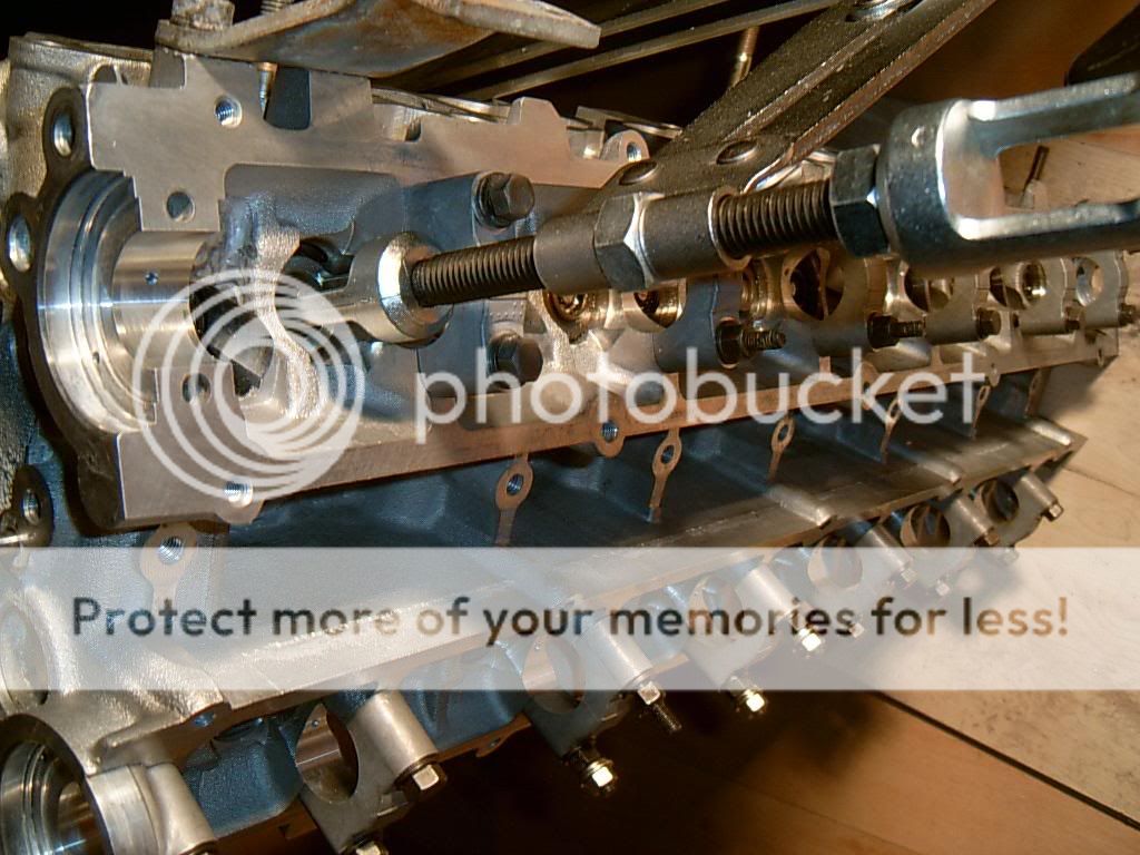

with the collets removed the spring and cap will come out as the valve tool is released and the valve can be pulled out with the plunger
keep all of the valves/springs/caps/collets/spring seating washers from each port in one bag labelled with the number of that port, i normally write the numbers next to one or two of the ports too as you can see in some pics...just to make sure they go back in the same place
here is one of the exhaust valves as it came out
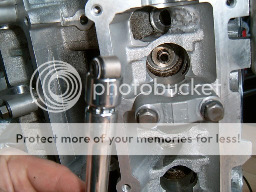
when the valve and spring/cap is removed you can see the valve seal
these can be removed *carefully* with a pair of pliers...must be careful not to score the wall of the head
l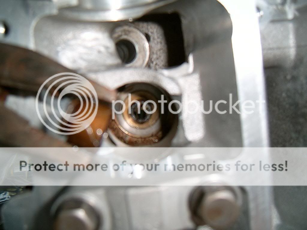
when everything is removed you can give all the parts a clean with fuel inc the parts of the exhaust ports that you cant get to with the valve in place....i wouldnt clean around the valve seat/valve sealing surface with anything other than cutting paste but you can clean the backs of the valves with a dremmel type wire brush end on a slow setting
with any dirt/grit out of the way the valves can be recut
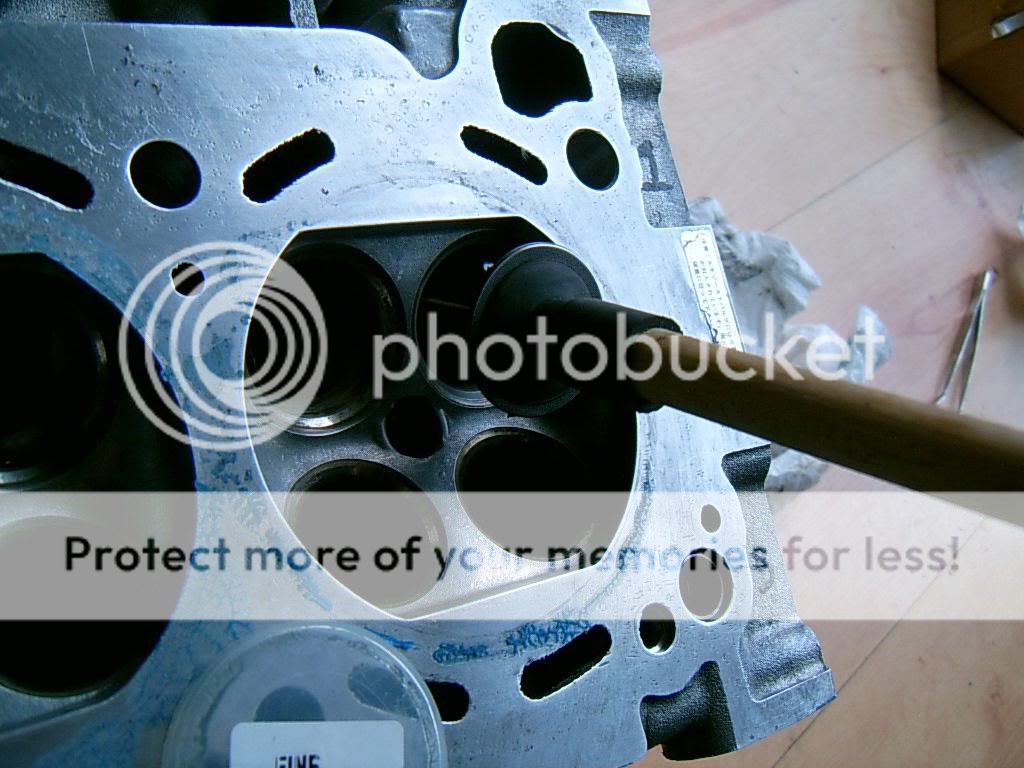
to cut the valves you apply three small dabs of corse paste onto the sealing surface at the back of the valve, you then insert it with the plunger and rotate the plunger like you are making fire on one of those discovery channels lol (you will need to then repeat with fine paste at least two more times or until you are satisfied that the paste is being pushed out of the sides of the valve in a uniform manner indicating that the valve seat has been matched)
you also need to lift up every few seconds and rotate the valve about 90 degrees before placing back down to make more "fire"
you can feel after only a few moments of rotation that the paste has been pushed out so you wipe up and repeat a couple more times with fine paste.....some valves/heads will need more cutting than others but in this game less is more.....if you remove lots of material you will at least affect the height of the shim (we will come to those later)
you can get marks on the valve mating surface but some of these will not come out no matter how much fire you make
if you have not done this before you will need these
the idea is to clamp the valve spring down and remove the "collets" from the top of the valve
with the collets removed the spring and cap will come out as the valve tool is released and the valve can be pulled out with the plunger
keep all of the valves/springs/caps/collets/spring seating washers from each port in one bag labelled with the number of that port, i normally write the numbers next to one or two of the ports too as you can see in some pics...just to make sure they go back in the same place
here is one of the exhaust valves as it came out
when the valve and spring/cap is removed you can see the valve seal
these can be removed *carefully* with a pair of pliers...must be careful not to score the wall of the head
l
when everything is removed you can give all the parts a clean with fuel inc the parts of the exhaust ports that you cant get to with the valve in place....i wouldnt clean around the valve seat/valve sealing surface with anything other than cutting paste but you can clean the backs of the valves with a dremmel type wire brush end on a slow setting
with any dirt/grit out of the way the valves can be recut
to cut the valves you apply three small dabs of corse paste onto the sealing surface at the back of the valve, you then insert it with the plunger and rotate the plunger like you are making fire on one of those discovery channels lol (you will need to then repeat with fine paste at least two more times or until you are satisfied that the paste is being pushed out of the sides of the valve in a uniform manner indicating that the valve seat has been matched)
you also need to lift up every few seconds and rotate the valve about 90 degrees before placing back down to make more "fire"
you can feel after only a few moments of rotation that the paste has been pushed out so you wipe up and repeat a couple more times with fine paste.....some valves/heads will need more cutting than others but in this game less is more.....if you remove lots of material you will at least affect the height of the shim (we will come to those later)
you can get marks on the valve mating surface but some of these will not come out no matter how much fire you make
09-06-2006, 10:00 AM
#9
Wahay!! I've lost my Virginity!!
Thread Starter
Join Date: Oct 2005
Posts: 53
Likes: 0
Received 0 Likes
on
0 Posts
here is a valve in the process of being cut, paste applied to the back of the valve
after you have cut 24 valves the seals are next on the list, if you dont have a press to fit these you can do it with a socket, extention and a small hammer, not a job for the ham fisted!
oil seal then place seal onto "stem" and tap in, i removed all of the seal springs first to avoid damage and refitted them after
oil the valve and push it gently through the new seal into its home then install the washer/spring/cap and compress with the valve tool
getting the collets back on is a hell of a lot easier with some grease applied to them first

one they are home just release the tool and everything should fit snug, it takes some time to do them all

well the block is already prepped we just gave it a turn or two so the pistons were on average half way down their bores (to avoid any piston/valve contact when the cams are fitted later on), and fitted the gaskett
a bit of oil over the tops of the new pistons before we lock them away
thanks must be given to "JohnB" for the practical and theory input on this thread and on this engine, a pleasure to work with
also thanks to "JohnA" for putting up with persistant questions lol
the shims and buckets are yet to be measured and fitted before the cams go on to have the tolorances on them checked but i will come back to this...for now i am more interested in fitting the engine
after you have cut 24 valves the seals are next on the list, if you dont have a press to fit these you can do it with a socket, extention and a small hammer, not a job for the ham fisted!
oil seal then place seal onto "stem" and tap in, i removed all of the seal springs first to avoid damage and refitted them after
oil the valve and push it gently through the new seal into its home then install the washer/spring/cap and compress with the valve tool
getting the collets back on is a hell of a lot easier with some grease applied to them first
one they are home just release the tool and everything should fit snug, it takes some time to do them all
well the block is already prepped we just gave it a turn or two so the pistons were on average half way down their bores (to avoid any piston/valve contact when the cams are fitted later on), and fitted the gaskett
a bit of oil over the tops of the new pistons before we lock them away
thanks must be given to "JohnB" for the practical and theory input on this thread and on this engine, a pleasure to work with
also thanks to "JohnA" for putting up with persistant questions lol
the shims and buckets are yet to be measured and fitted before the cams go on to have the tolorances on them checked but i will come back to this...for now i am more interested in fitting the engine
09-06-2006, 10:00 AM
#10
Wahay!! I've lost my Virginity!!
Thread Starter
Join Date: Oct 2005
Posts: 53
Likes: 0
Received 0 Likes
on
0 Posts
the engine has a lot of stuff that needs to be connected before the engine is fitted, because they were all cleaned beforehand it only takes a couple of hours to refit and TBH if i wasnt too sure where something went i just checked the earlier pics i took on its way out
i did have a rather noisey nismo paddle clutch fitted, its being replaced by a single plate exedy uprated version
heres a set of shots of the engine dressed
an input shaft from an old skyline gearbox is the best tool to line the clutch up with as you clamp it down but they are not easy to come by...this one was lent to me by tony of abbey motorsport
rigging the engine to the crane is pretty important with a fully loaded RB26DETT, the engine is very heavy and it will snap chains as i found out shortly after taking the three pics above
the rigging broke and the rebuilt engine fell approx 1 meter into paving slabs and into the front of the car, i expected serious engine damage but the block was untouched....it came down on one of the bottom corners and just took a hole out of one of the slabs before resting itself on the front bumper, scarey stuff really

the 250kg engine stand we used during the rebuild was also bent by the weight of the block when the head and sump, turbos and inlet etc were connected...be careful out there lol
so with some upgraded rigging we started to reinstall the engine (please note that the pin on the gear fork should now be fitted!!)
i found it was far easier to get the lump into position if i had the front of the engine raised above the fly end, it lifts out real easy on the way out and that isnt easy to duplicate on the way in
once i had the engine where i wanted it we had to play with the height of the gearbox/engine to position it correctly so the splines would be at the correct angle to the splines.......i didnt think that it "felt right" at first, there was far too much resistance as the spline went in for my liking but thats how they are on these, once you get this far you know its in, bolt the fecker up!
after that you need to refit the rest of the equipment, driveshafts, pumps, various wires hoses...all straightforward really
back to the head then!
i did have a rather noisey nismo paddle clutch fitted, its being replaced by a single plate exedy uprated version
heres a set of shots of the engine dressed
an input shaft from an old skyline gearbox is the best tool to line the clutch up with as you clamp it down but they are not easy to come by...this one was lent to me by tony of abbey motorsport
rigging the engine to the crane is pretty important with a fully loaded RB26DETT, the engine is very heavy and it will snap chains as i found out shortly after taking the three pics above
the rigging broke and the rebuilt engine fell approx 1 meter into paving slabs and into the front of the car, i expected serious engine damage but the block was untouched....it came down on one of the bottom corners and just took a hole out of one of the slabs before resting itself on the front bumper, scarey stuff really
the 250kg engine stand we used during the rebuild was also bent by the weight of the block when the head and sump, turbos and inlet etc were connected...be careful out there lol
so with some upgraded rigging we started to reinstall the engine (please note that the pin on the gear fork should now be fitted!!)
i found it was far easier to get the lump into position if i had the front of the engine raised above the fly end, it lifts out real easy on the way out and that isnt easy to duplicate on the way in
once i had the engine where i wanted it we had to play with the height of the gearbox/engine to position it correctly so the splines would be at the correct angle to the splines.......i didnt think that it "felt right" at first, there was far too much resistance as the spline went in for my liking but thats how they are on these, once you get this far you know its in, bolt the fecker up!
after that you need to refit the rest of the equipment, driveshafts, pumps, various wires hoses...all straightforward really
back to the head then!
09-06-2006, 10:01 AM
#11
Wahay!! I've lost my Virginity!!
Thread Starter
Join Date: Oct 2005
Posts: 53
Likes: 0
Received 0 Likes
on
0 Posts
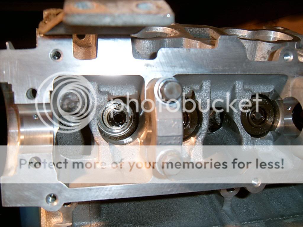
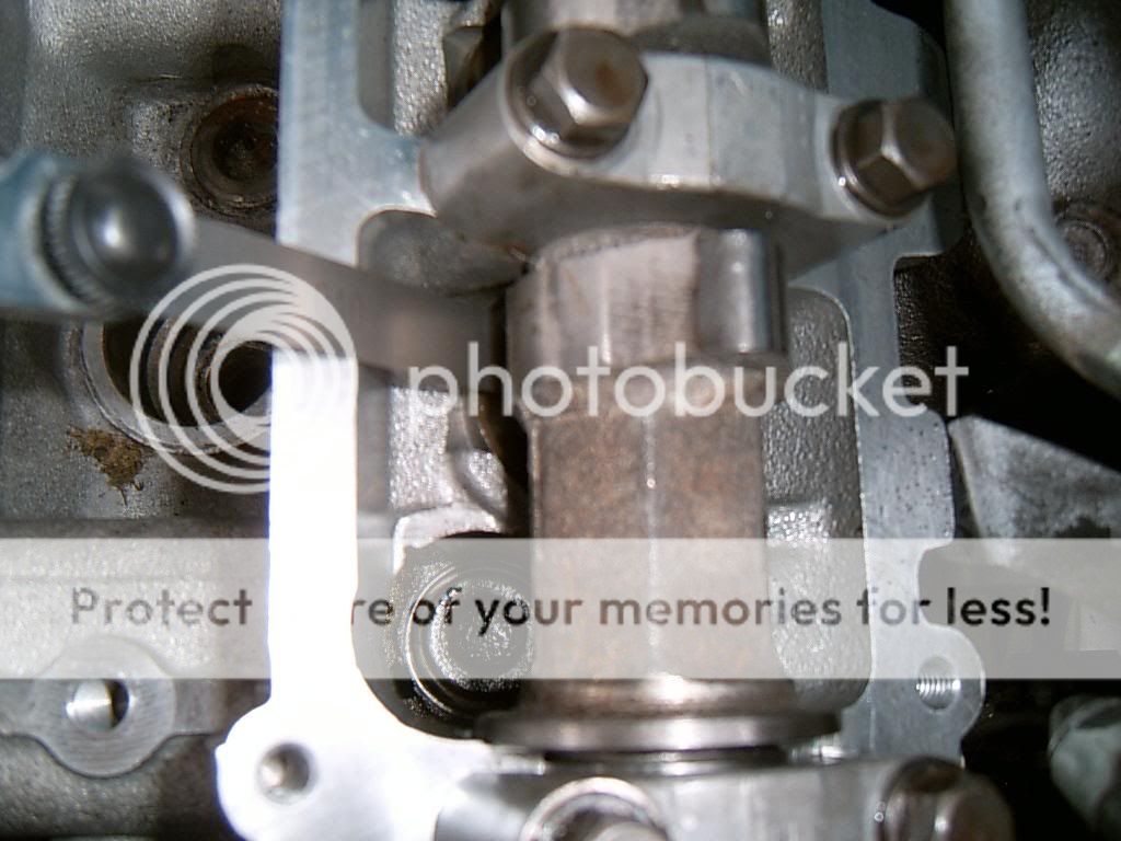
with the engine now fitted we can address the valve clearance
the cam cap bolts were stuck inside the cam caps, needed hours of penetrating fluid to release them....be really careful here, you dont want to snap one inside the cap...if you do it may requitre drilling out and if you dont do it just right it will kill the cap and you will be paying �1200 for a replacement head!, caps are not interchangeable! (or so i am led to believe, never tried it TBH)
youi can see here that the valve closest to the camera has a shim and a bucket installed, you may see on valve no2 that only yhr shim is installed, note that the shim is the wrong way around so that the impact/pecussion mark from the valve is pointing up rather than down towarsds the valve, this will help bring it to the standard clearance
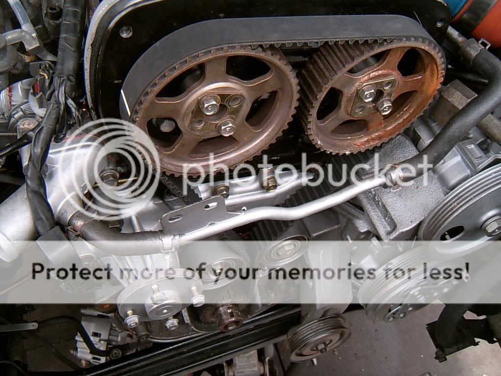
inlet cam placed into position
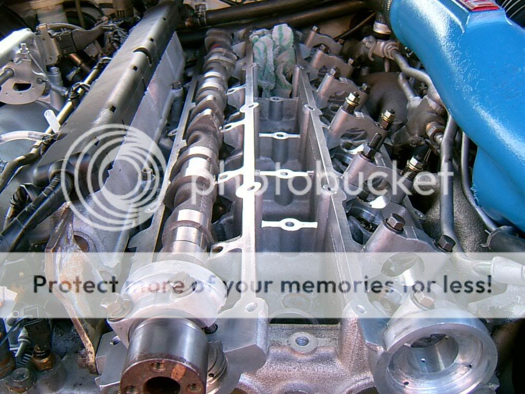
here you see the cam in its natural enviroment, clamped down to the head
its really easy to bend a cam doing this...make sure that you take it down equally
with the cam clamped down we can check clearance between the bucket and the cam, rotate the cam so the valve is closed (with the lobe pointing up) and insert a feeler guage under the cam, clearance is 1-18 thou, mine came up at 10 thou acroos the board on the inlet side.....some people will always want to go to the high end of the clearance "so they know the valve is fully closed" but this will do for me, middle of the clearance is fine IMHO
rocker cover fitted
exhaust cam fitted, clearance on this side is 1-16thou for the valve
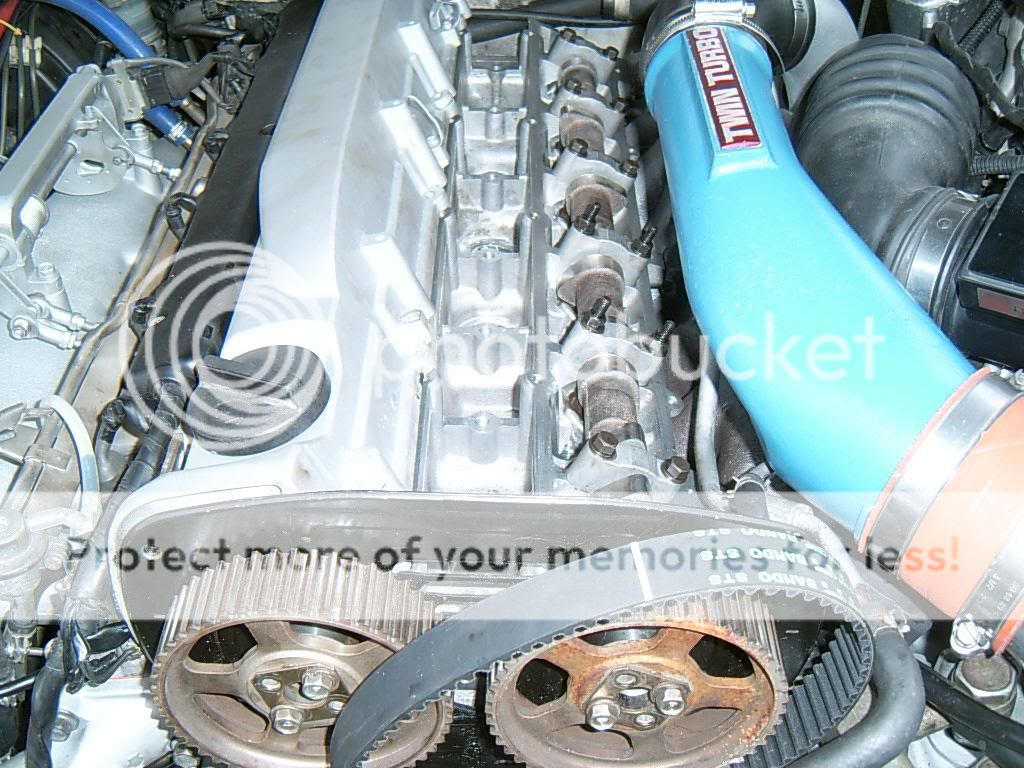
ready to do the timing now!, we are almost there!!
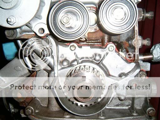
this pic just points out the stock inlet cam timing mark
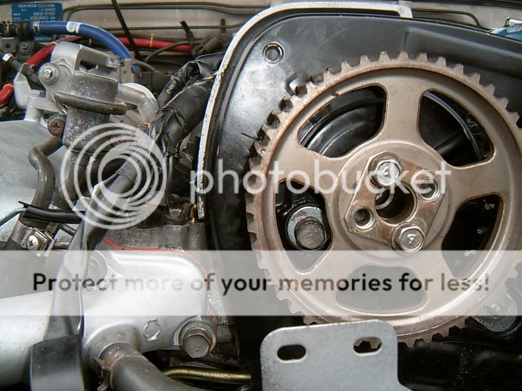
the white line on the belt is positioned next to the crank timing mark
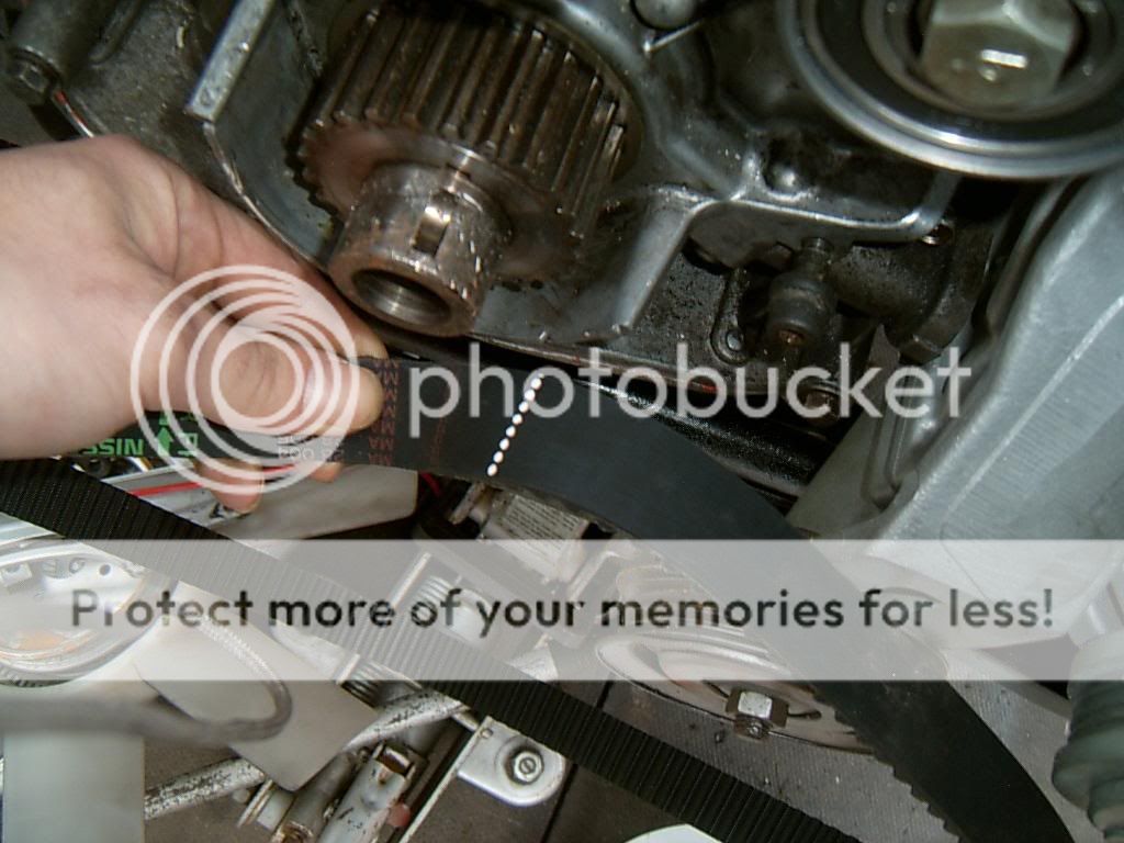
all marks lined up now, belt fitted and adjusted for tension with the adjuster, rotate the engine twice and line the marks back up to assure timing is correct......i had to redo the timing on my first go at this so make sure you rotate twice and check!!
the cam cap bolts were stuck inside the cam caps, needed hours of penetrating fluid to release them....be really careful here, you dont want to snap one inside the cap...if you do it may requitre drilling out and if you dont do it just right it will kill the cap and you will be paying �1200 for a replacement head!, caps are not interchangeable! (or so i am led to believe, never tried it TBH)
youi can see here that the valve closest to the camera has a shim and a bucket installed, you may see on valve no2 that only yhr shim is installed, note that the shim is the wrong way around so that the impact/pecussion mark from the valve is pointing up rather than down towarsds the valve, this will help bring it to the standard clearance
inlet cam placed into position
here you see the cam in its natural enviroment, clamped down to the head
its really easy to bend a cam doing this...make sure that you take it down equally
with the cam clamped down we can check clearance between the bucket and the cam, rotate the cam so the valve is closed (with the lobe pointing up) and insert a feeler guage under the cam, clearance is 1-18 thou, mine came up at 10 thou acroos the board on the inlet side.....some people will always want to go to the high end of the clearance "so they know the valve is fully closed" but this will do for me, middle of the clearance is fine IMHO
rocker cover fitted
exhaust cam fitted, clearance on this side is 1-16thou for the valve
ready to do the timing now!, we are almost there!!
this pic just points out the stock inlet cam timing mark
the white line on the belt is positioned next to the crank timing mark
all marks lined up now, belt fitted and adjusted for tension with the adjuster, rotate the engine twice and line the marks back up to assure timing is correct......i had to redo the timing on my first go at this so make sure you rotate twice and check!!
09-06-2006, 10:02 AM
#12
Wahay!! I've lost my Virginity!!
Thread Starter
Join Date: Oct 2005
Posts: 53
Likes: 0
Received 0 Likes
on
0 Posts
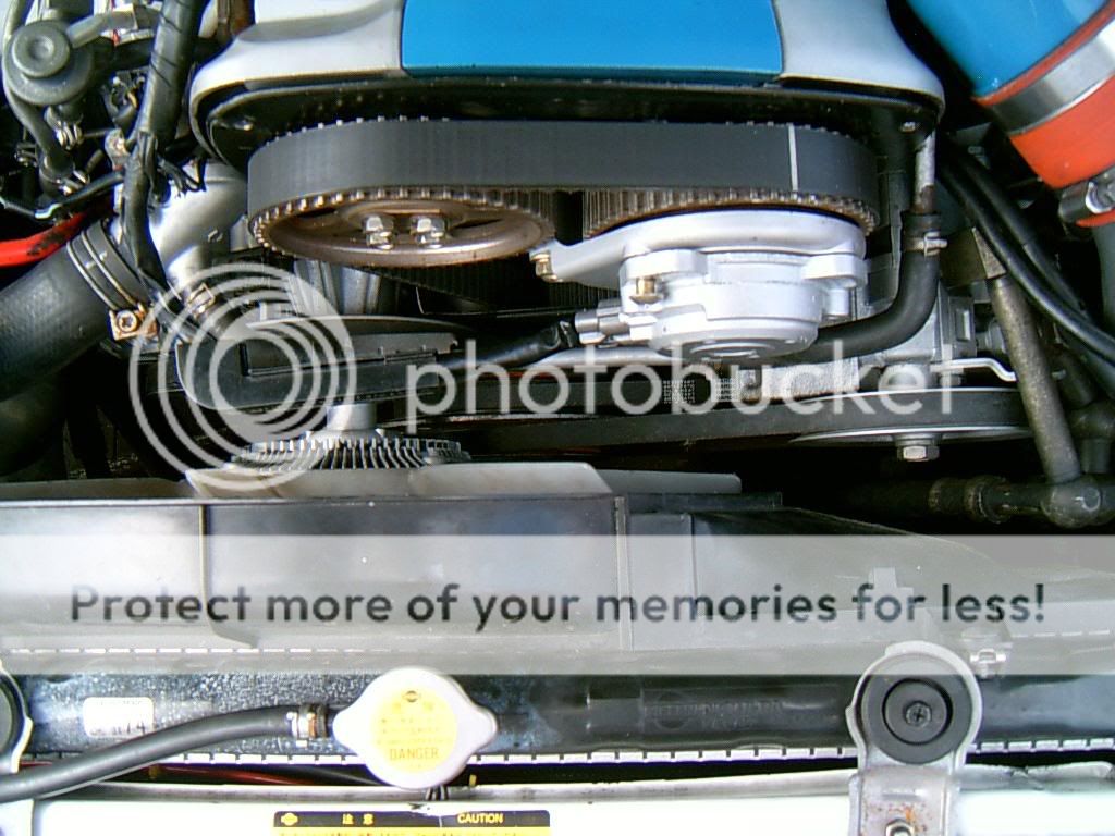
so its time to fit the belt pulley and fit the belts for the power steering, alternator and air con pump!
i used a new keyway as mine was "lost", the stock torque setting for the crank bolt is 340-350LBFT (jeez!)
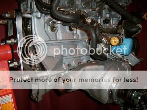
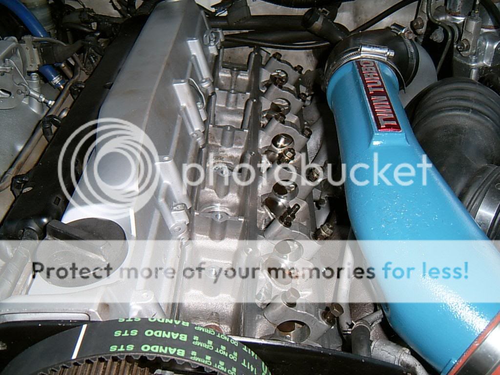
so the engine is pretty much finished now.....its been removed, fully rebuilt and reinstalled
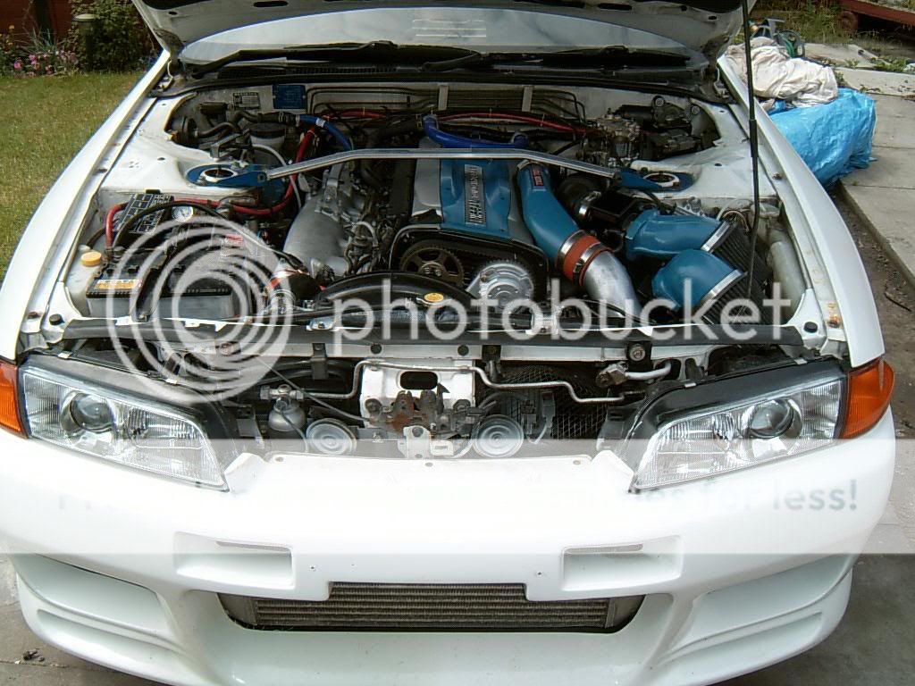
compression was 140psi across the board
quite a difference from the previous incarnation of what lurked under that bonnet i think you will agree? (also note the fibreglass and spraycan repair of the bumper from the engine install post lol)
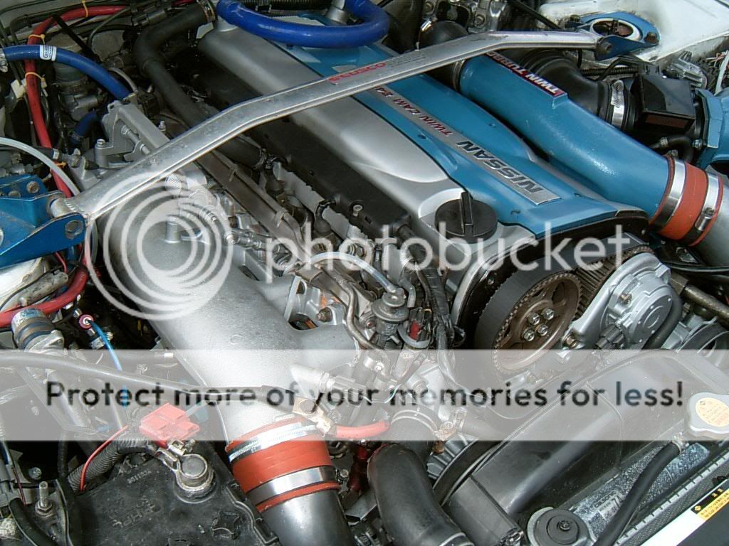
the finished article?

only one slight problem, it wont bloody start up! and i have no idea where to look at this moment in time
i used a new keyway as mine was "lost", the stock torque setting for the crank bolt is 340-350LBFT (jeez!)
so the engine is pretty much finished now.....its been removed, fully rebuilt and reinstalled
compression was 140psi across the board
quite a difference from the previous incarnation of what lurked under that bonnet i think you will agree? (also note the fibreglass and spraycan repair of the bumper from the engine install post lol)
the finished article?
only one slight problem, it wont bloody start up! and i have no idea where to look at this moment in time
09-06-2006, 10:25 AM
#13
PassionFord Post Whore!!
iTrader: (9)
Join Date: May 2003
Location: Essex/Middlesex
Posts: 7,836
Likes: 0
Received 0 Likes
on
0 Posts
EXCELLENT and very informative rebuild mate.
love all the concise pics and detailed explanation of what you're doing
Hope its just a small problem that is stopping it from starting!!
love all the concise pics and detailed explanation of what you're doing
Hope its just a small problem that is stopping it from starting!!

 09-06-2006, 10:34 AM
#16
Wahay!! I've lost my Virginity!!
Thread Starter
Join Date: Oct 2005
Posts: 53
Likes: 0
Received 0 Likes
on
0 Posts
i have a few more posts to add but didnt add them due top the car not working yet, concerns methonol and water injection and choice of gauges etc, should i stick them up too?
09-06-2006, 10:36 AM
#17
Fucking superstar........
Join Date: May 2004
Location: Argyll.... It's lonely...
Posts: 13,240
Likes: 0
Received 0 Likes
on
0 Posts
You certainly know what you're doing. A good read.
And you can type properly which makes reading your posts so much easier on my poor tired brain  09-06-2006, 11:00 AM
#18
Wahay!! I've lost my Virginity!!
Thread Starter
Join Date: Oct 2005
Posts: 53
Likes: 0
Received 0 Likes
on
0 Posts
while we to work out why it wont start it gives some time to fit the gauges..
all we know at this point is that the engine blew from a suspected lean condition (see piston ringland pics on page one)
we cant really run this at anything other than idle without first checking and confirming fuelling is correct
here you can see a AEM UEGO wideband controller, a "pyrometer" for exhaust gas temprature display and a oil pressure display (it has one in the spedo as stock and TBH ill be swoping this over for a oil temp guage ASAP)
i also installed a "knocklink" display in the upper part of the speedo to monitor detonation, these are not "that good" really and in my experiance they tend to monitor misfires more than anything else so ill be checking for detonation with "det cans" (we will come to this later), far cheaper, more professoinal and far more dependable if you have a good ear

we also have a intake temp guage, it was a cheap ebay item i must admit but i do not expect intake temps to be that high with the size of this intercooler and the fact that ill be using a maximum of 1BAR pressure, the install is a bit "crap" lol, ill have to do that properly in the future

here we have a fuel pressure guage, its just for monitoring pressure at idle but will come in handy if i need to install a fuel pressure regulator to increase fuelling slightly
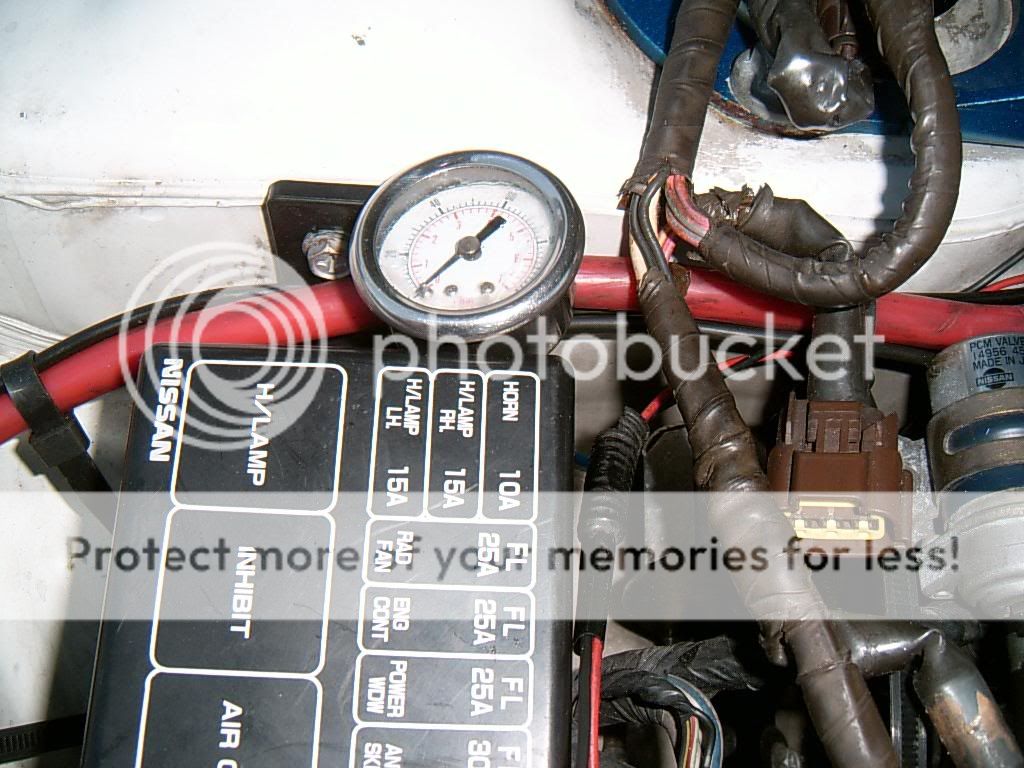
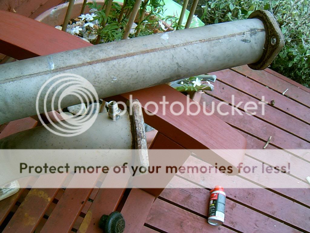
the fuel guage T piece.....an easy and cheap way of hooking the guage up to the supply, here we see it prior to installiation
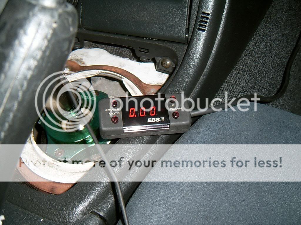
a boost controoler is obviously a must, the car came with this controller and ill give it the benifit of the doubt and use it to help set the car up
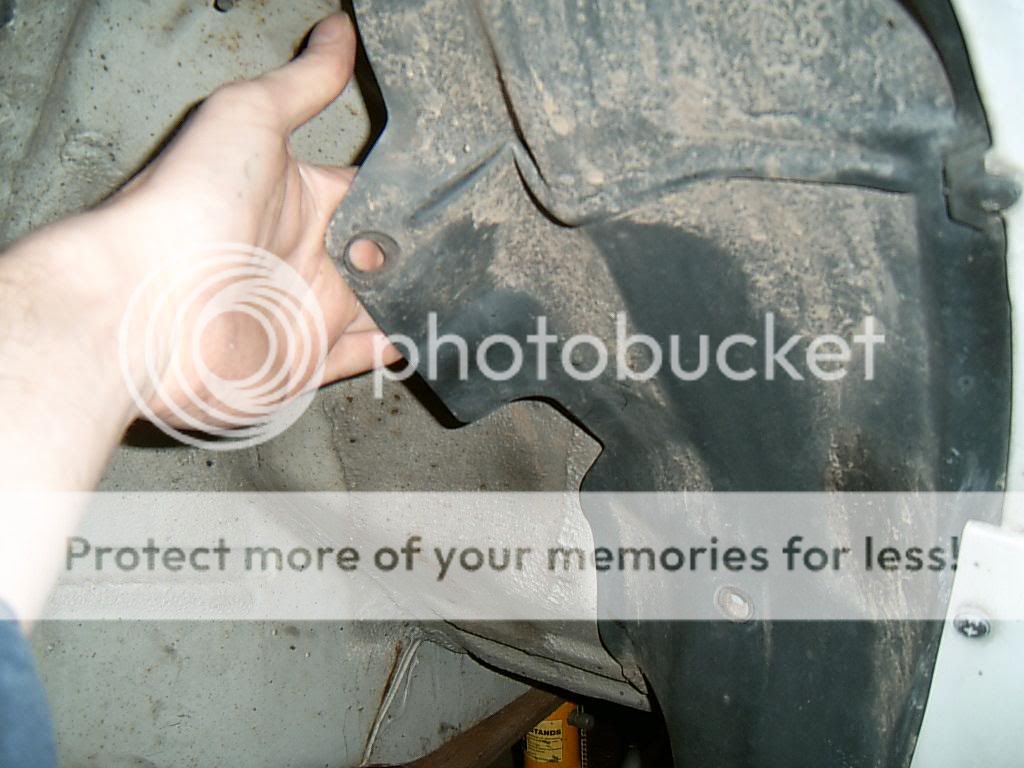
i needed to get a load of wires into the cockpit for these guages.....the bulkhead wire point is just behind the passenger wheel arch, quite easy to get them through when you know where it is, you may need to remove the passenger footwell plastics to retrieve them from the cockpit side
the wideband unit and pyrometer will both need to be installed in the exhaust, really the pyrometer should be installed before the turbo, here you see it right after the rear turbo
all we know at this point is that the engine blew from a suspected lean condition (see piston ringland pics on page one)
we cant really run this at anything other than idle without first checking and confirming fuelling is correct
here you can see a AEM UEGO wideband controller, a "pyrometer" for exhaust gas temprature display and a oil pressure display (it has one in the spedo as stock and TBH ill be swoping this over for a oil temp guage ASAP)
i also installed a "knocklink" display in the upper part of the speedo to monitor detonation, these are not "that good" really and in my experiance they tend to monitor misfires more than anything else so ill be checking for detonation with "det cans" (we will come to this later), far cheaper, more professoinal and far more dependable if you have a good ear
we also have a intake temp guage, it was a cheap ebay item i must admit but i do not expect intake temps to be that high with the size of this intercooler and the fact that ill be using a maximum of 1BAR pressure, the install is a bit "crap" lol, ill have to do that properly in the future
here we have a fuel pressure guage, its just for monitoring pressure at idle but will come in handy if i need to install a fuel pressure regulator to increase fuelling slightly
the fuel guage T piece.....an easy and cheap way of hooking the guage up to the supply, here we see it prior to installiation
a boost controoler is obviously a must, the car came with this controller and ill give it the benifit of the doubt and use it to help set the car up
i needed to get a load of wires into the cockpit for these guages.....the bulkhead wire point is just behind the passenger wheel arch, quite easy to get them through when you know where it is, you may need to remove the passenger footwell plastics to retrieve them from the cockpit side
the wideband unit and pyrometer will both need to be installed in the exhaust, really the pyrometer should be installed before the turbo, here you see it right after the rear turbo
09-06-2006, 11:02 AM
#19
Wahay!! I've lost my Virginity!!
Thread Starter
Join Date: Oct 2005
Posts: 53
Likes: 0
Received 0 Likes
on
0 Posts
while we to work out why it wont start it gives some time to fit the gauges..
all we know at this point is that the engine blew from a suspected lean condition (see piston ringland pics on page one)
we cant really run this at anything other than idle without first checking and confirming fuelling is correct
here you can see a AEM UEGO wideband controller, a "pyrometer" for exhaust gas temprature display and a oil pressure display (it has one in the spedo as stock and TBH ill be swoping this over for a oil temp guage ASAP)
i also installed a "knocklink" display in the upper part of the speedo to monitor detonation, these are not "that good" really and in my experiance they tend to monitor misfires more than anything else so ill be checking for detonation with "det cans" (we will come to this later), far cheaper, more professoinal and far more dependable if you have a good ear
we also have a intake temp guage, it was a cheap ebay item i must admit but i do not expect intake temps to be that high with the size of this intercooler and the fact that ill be using a maximum of 1BAR pressure, the install is a bit "crap" lol, ill have to do that properly in the future
here we have a fuel pressure guage, its just for monitoring pressure at idle but will come in handy if i need to install a fuel pressure regulator to increase fuelling slightly
the fuel guage T piece.....an easy and cheap way of hooking the guage up to the supply, here we see it prior to installiation
a boost controoler is obviously a must, the car came with this controller and ill give it the benifit of the doubt and use it to help set the car up
i needed to get a load of wires into the cockpit for these guages.....the bulkhead wire point is just behind the passenger wheel arch, quite easy to get them through when you know where it is, you may need to remove the passenger footwell plastics to retrieve them from the cockpit side
the wideband unit and pyrometer will both need to be installed in the exhaust, really the pyrometer should be installed before the turbo, here you see it right after the rear turbo
09-06-2006, 11:03 AM
#20
Wahay!! I've lost my Virginity!!
Thread Starter
Join Date: Oct 2005
Posts: 53
Likes: 0
Received 0 Likes
on
0 Posts
in an attempt to keep the jap 100 octane chip ill try to increase the octane of the fuel to jap spec, we cant buy anything higher than 99 octane in the UK and even this fuel (tesco) was slated in a recent mag test........working with companys whos products are tested in mags quite frequently i do however know that 90% of these tests are actually rigged so ill take no notice of that test at all, if you have read this far i guees you already suspect that im not an optimist and ill trust my own findings over anyone elses (although i hope you will trust mine lol)
if i need to change to a UK chip at least i will have had a go lol
i intend to inject a water methonol mix to increase octane from 99RON to around 105RON, hopefully this should result on a car that works fine on a jap preformance chip and has more driveability than the UK counterparts running on 1 bar (more ignition advance!!)
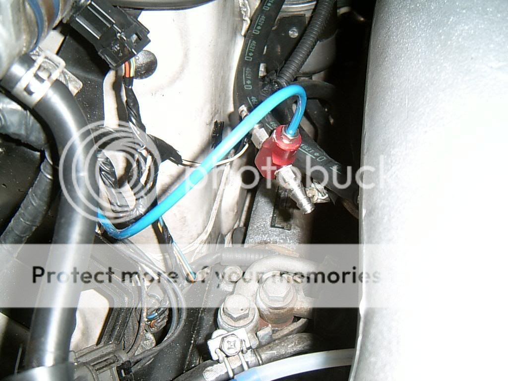
here is the waterpump, it found its home under the air filters for the moment but eviction looms in the air as that position will soon be filled by an extra cold air intake for the filters/relocation of the filters so they sit in the bumper vent
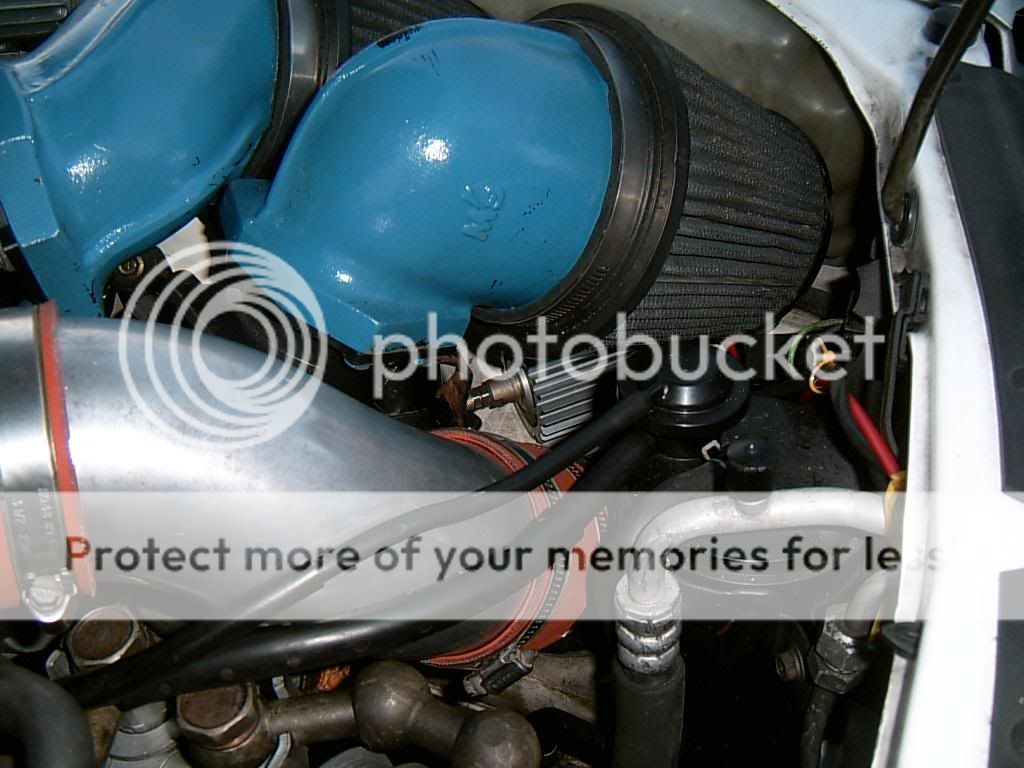
here is the injection point just before the plenium, you cvan see the intake temp guage wire poking into the hose from the top of
if i need to change to a UK chip at least i will have had a go lol
i intend to inject a water methonol mix to increase octane from 99RON to around 105RON, hopefully this should result on a car that works fine on a jap preformance chip and has more driveability than the UK counterparts running on 1 bar (more ignition advance!!)
here is the waterpump, it found its home under the air filters for the moment but eviction looms in the air as that position will soon be filled by an extra cold air intake for the filters/relocation of the filters so they sit in the bumper vent
here is the injection point just before the plenium, you cvan see the intake temp guage wire poking into the hose from the top of
09-06-2006, 12:15 PM
#21
I've found that life I needed.. It's HERE!!

Join Date: Jul 2004
Location: Cumbria/Preston
Posts: 1,294
Likes: 0
Received 0 Likes
on
0 Posts
I recognise this rebuild thread!  Was it on the SkylineOwners forum or another? Glad to see it's back in the car now...I wonder why it won't start??
Crank sensor
Fuel pressure
Do you have sparks at the plugs?
Are you getting fuel through?
Fuel pump(s) priming and running?
I'm sure you know what to check if you're willing to rebuild the RB!!
Crank sensor
Fuel pressure
Do you have sparks at the plugs?
Are you getting fuel through?
Fuel pump(s) priming and running?
I'm sure you know what to check if you're willing to rebuild the RB!!
09-06-2006, 12:19 PM
#22
Wahay!! I've lost my Virginity!!
Thread Starter
Join Date: Oct 2005
Posts: 53
Likes: 0
Received 0 Likes
on
0 Posts
Originally Posted by heeman10
I recognise this rebuild thread! Was it on the SkylineOwners forum or another? Glad to see it's back in the car now...I wonder why it won't start??
Crank sensor
Fuel pressure
Do you have sparks at the plugs?
Are you getting fuel through?
Fuel pump(s) priming and running?
I'm sure you know what to check if you're willing to rebuild the RB!!
Crank sensor
Fuel pressure
Do you have sparks at the plugs?
Are you getting fuel through?
Fuel pump(s) priming and running?
I'm sure you know what to check if you're willing to rebuild the RB!!
no crank sensor on the car but it does have a cam sensor that does the same job, i dont know how to check it or set it up
09-06-2006, 12:22 PM
#23
I've found that life I needed.. It's HERE!!
Join Date: Jul 2004
Location: Cumbria/Preston
Posts: 1,294
Likes: 0
Received 0 Likes
on
0 Posts
You'd think that even timed up completely out of sync, if an engine's getting fuel and spark...it would do SOMEthing!!  The sensor must be doing its job if it's sparking, surely? So no need to change it?? Please keep this thread updated, and post up any findings...good luck! I'm sure people will reply if you tell us what's happening, and give suggestions etc
09-06-2006, 12:28 PM
#24
Wahay!! I've lost my Virginity!!
Thread Starter
Join Date: Oct 2005
Posts: 53
Likes: 0
Received 0 Likes
on
0 Posts
well you can see the timing pics above....i even took it back apart to double check
i guess im getting spark and fuel at slightly the wrong time or maybe the AFR is out and its too rich
or maybe i have lost a wire, rigged summat up wrong.......i really dont know, im totally stumped TBH
i wrote this guide and now the last part of the guide basicially says "take car to someone who knows what they are doing" lol.........its not the way i wanted it but i cant fix it, i dont know what i need to do
i have spend approx 3 full days going over plugs and stuff, disconnecting this, moving that, no good
09-06-2006, 01:03 PM
#25
I'm Finding My Feet Here Now

Join Date: Apr 2005
Posts: 140
Likes: 0
Received 0 Likes
on
0 Posts
when i rebuilt my ca18det in my 200 sx the CAS (crank angle sensor) run off the cam, which by the looks of it is identical to yours was out of position,
basically i undone all the bolts to it and got my dad to turn the car over while i rotated it, the car promptly fired and it apeared that for some reason the cover that held the sensor would not allow enough movement with the bolts in to put the CAS in the correct place, pain in the arse really cos i had to file the slots in the CAS out to get more rotation,
basically i undone all the bolts to it and got my dad to turn the car over while i rotated it, the car promptly fired and it apeared that for some reason the cover that held the sensor would not allow enough movement with the bolts in to put the CAS in the correct place, pain in the arse really cos i had to file the slots in the CAS out to get more rotation,
09-06-2006, 03:52 PM
#26
Wahay!! I've lost my Virginity!!
Thread Starter
Join Date: Oct 2005
Posts: 53
Likes: 0
Received 0 Likes
on
0 Posts
yea we tried that too, moving the sensor whilst cranking....didnt seem to make a difference 
anyone else have any more suggestions?, i dont care how silly they are as this is probably a silly problem
regards, brian
anyone else have any more suggestions?, i dont care how silly they are as this is probably a silly problem
regards, brian
09-06-2006, 05:53 PM
#27
I've found that life I needed.. It's HERE!!
Join Date: Jul 2004
Location: Cumbria/Preston
Posts: 1,294
Likes: 0
Received 0 Likes
on
0 Posts
What exactly is it doing when you turn it over? Coughing as though it's trying to start at all?
1. You clearly have good compression
2. You're getting fuel
3. You're getting spark - so CAS must be working..perhaps just not quite as it should?? Can you get access to another to try?
1. You clearly have good compression
2. You're getting fuel
3. You're getting spark - so CAS must be working..perhaps just not quite as it should?? Can you get access to another to try?

 11-06-2006, 12:35 PM
#31
10K+ Poster!!
iTrader: (1)

Join Date: May 2003
Location: Lancashire
Posts: 12,748
Likes: 0
Received 0 Likes
on
0 Posts
Originally Posted by TFS
yea we tried that too, moving the sensor whilst cranking....didnt seem to make a difference
anyone else have any more suggestions?, i dont care how silly they are as this is probably a silly problem
regards, brian
anyone else have any more suggestions?, i dont care how silly they are as this is probably a silly problem
regards, brian
11-06-2006, 09:56 PM
#32
Wahay!! I've lost my Virginity!!
Thread Starter
Join Date: Oct 2005
Posts: 53
Likes: 0
Received 0 Likes
on
0 Posts
well it seems i stumbled across the problem....
the cam/crank sensor controls spark/ignition timing....the sensor needs to sit in the correct location on the exhaust cam...the only way to get the sensor fully onto the cam is to have it in the correct position so you cant really go wrong, it only fits on one way
the inlet cam does not have this part however....if you tried to fit it on the inlet cam you would find it would go in any on way and would still spin the sensor hence providing a spark...at a totally random time i hasen to add
so.....
it all becomes clear when i find not one but two inlet cams on the car and no sign of an exhaust cam..ahem
one of the original cams had marks on the lobe so i ordered a replaement one (second hand), it seems i was either sent the wrong one, fitted the scored one or ordered the wrong one, either way i have fitted the wrong one as neither cam has a keyway bit fot the sensor to locate into and unless im mistaken this means the ignition timing could be so far out its no wonder it wont fire up eh?
 14-06-2006, 10:24 PM
#34
DEYTUKURJERBS

Ah, forgot to reply.
Great thread, esp the stuff on the headwork.
I bet you could show a lot of people this thread and theyd still believe its impossible and GTR engines are magical things that only Japanese people and tuners that charge 100quid an hour are able to fix
Great thread, esp the stuff on the headwork.
I bet you could show a lot of people this thread and theyd still believe its impossible and GTR engines are magical things that only Japanese people and tuners that charge 100quid an hour are able to fix
15-06-2006, 10:04 AM
#35
20K+ Super Poster.
iTrader: (1)
Join Date: May 2003
Location: Essex... and Birmingham!
Posts: 21,512
Likes: 0
Received 0 Likes
on
0 Posts
Originally Posted by Stavros
Ah, forgot to reply.
Great thread, esp the stuff on the headwork.
I bet you could show a lot of people this thread and theyd still believe its impossible and GTR engines are magical things that only Japanese people and tuners that charge 100quid an hour are able to fix
Great thread, esp the stuff on the headwork.
I bet you could show a lot of people this thread and theyd still believe its impossible and GTR engines are magical things that only Japanese people and tuners that charge 100quid an hour are able to fix
Great read
by the way Steve if you do ever need any pro work done that you do actually need to pay for then Rktuning is comically cheap!!!! VERY impressed!
15-06-2006, 10:21 PM
#36
Wahay!! I've lost my Virginity!!
Thread Starter
Join Date: Oct 2005
Posts: 53
Likes: 0
Received 0 Likes
on
0 Posts
Originally Posted by Stavros
I bet you could show a lot of people this thread and theyd still believe its impossible and GTR engines are magical things that only Japanese people and tuners that charge 100quid an hour are able to fix

Thread
Thread Starter
Forum
Replies
Last Post
nicodinho
Ford Non RS / XR / ST parts for sale.
6
07-10-2015 12:56 PM
Mc5506
Ford Escort RS Turbo
6
05-10-2015 09:57 PM