
My 397BHP Zetec Turbo 3dr. Its over...


 23-06-2009, 12:35 AM
#1126
Mr. Sparkle!
Join Date: Nov 2005
Location: Wiltshire - swindon
Posts: 12,775
Likes: 0
Received 0 Likes
on
0 Posts
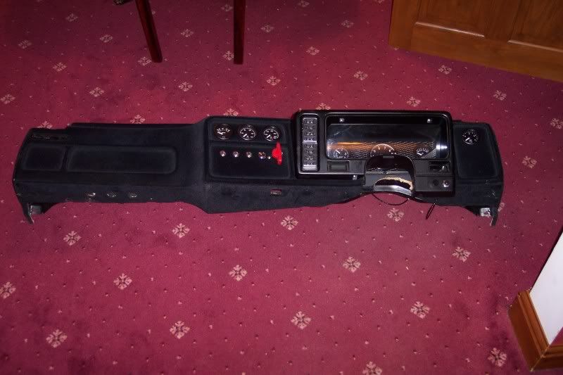
Nice Carpet LOL
Good work Dan, your have to video the moment you turn the key....i mean as we will be driving around in hover cars that run water by then LOL
Good work Dan, your have to video the moment you turn the key....i mean as we will be driving around in hover cars that run water by then LOL
23-06-2009, 06:48 AM
#1128
BANNED
BANNED

Join Date: Jun 2009
Location: NY
Posts: 4
Likes: 0
Received 0 Likes
on
0 Posts
23-06-2009, 07:58 AM
#1129
cheers guys, and yes the carpet is horrific!
we moved in about 5 weeks ago, and if you think thats bad, you should see the wall paper
were starting decorating upstars first, so it will get done in due course lol!
right, im off to newquay!
we moved in about 5 weeks ago, and if you think thats bad, you should see the wall paper
were starting decorating upstars first, so it will get done in due course lol!
right, im off to newquay!
 23-06-2009, 08:35 PM
#1131
PassionFord Post Whore!!
Join Date: Jul 2004
Location: Wiltshire, Bath, chippenham area!
Posts: 7,428
Likes: 0
Received 4 Likes
on
4 Posts
think we cracked the worst of the wiring Fudge.
or rather, worked out what all the loose wires and plugs do that you ripped out the old car
still a long way off though to be fair.. things take a lot longer to do than you think !
or rather, worked out what all the loose wires and plugs do that you ripped out the old car
still a long way off though to be fair.. things take a lot longer to do than you think !
25-06-2009, 05:46 PM
#1132
vickers, i dont think it should be that bad now, spent the other night going through the haines and think i have worked out what wires are for the instrument cluster etc, and for the ign switch


 20-08-2009, 09:00 PM
#1147
no.
hopefully got the mapping programs now, if i can open the rar files. but then i need a windows 98 based system to run it, and my laptop has vista...
but i REALLY need the wiring diagram off simon to check everything. and i dont have that yet.
hopefully got the mapping programs now, if i can open the rar files. but then i need a windows 98 based system to run it, and my laptop has vista...
but i REALLY need the wiring diagram off simon to check everything. and i dont have that yet.
21-08-2009, 12:06 AM
#1149
PassionFord Post Whore!!
iTrader: (1)

Join Date: Aug 2003
Location: Hampshire
Posts: 3,834
Likes: 0
Received 0 Likes
on
0 Posts
That won't work mate
Fudgey, get winrar off the net - trial version.
There's a file named connect in the stuff I gave you, thats got all the pinouts for the ecu.
21-08-2009, 07:52 PM
#1151
cheers lads.
kev, i think its pretty much an L8 isnt it?
but it was wired up by simon to my old escort and i thought id copied the loom how it was in that, but obviously not.
its uding an edis 4 module and the zetec coilpack which is where my problems are i think...?
if i cant get the software to work and no one buys the car off my, ill have to save up for DTA or similar but i have gone so far over budget with it now, i dont think i can justify pissing more cash up the wall...
or rather the wife cant lol
21-08-2009, 08:33 PM
#1152
cheers kev, i have managed to unzip the files, cant open half of the files tho lol but going from the connect file it states
S.E.C.S S8 ECU CONNECTIONS (COSWORTH VERSION)
=============================================
PIN ORIGINAL ECU S8 (IF DIFFERENT)
-------------------------------------------------------------------------
1 POWER GROUND
2 LAMBDA SENSOR INPUT
3 CRANK SENSOR GROUND
4 CRANK SENSOR INPUT
5 PHASE SENSOR GROUND
6 KNOCK SENSOR GROUND / USER OUTPUT 2
7 PURGE VALVE / USER OUTPUT 1 - WATER INJECTION
8 DIAGNOSTIC SOCKET / INJECTOR 5
9 VREF MONITOR / USER INPUT 1
10 POWER RELAY
11 VREF NEGATIVE
12 GENERAL OUTPUT / WARNING LAMP OUTPUT
13 OCTANE ADJUST / INJECTOR 6
14 OCTANE ADJUST / INJECTOR 7
15 MAP SENSOR INPUT
16 BOOST VALVE
17 THROTTLE POSITION
18 INJECTOR 4
19 POWER GROUND
20 POSITIVE SUPPLY
21 - / TACHO DRIVE OUTPUT
22 KNOCK SENSOR INPUT / USER INPUT 2
23 PHASE SENSOR INPUT
24 IGNITION TRIGGER GROUND
25 IGNITION TRIGGER OUTPUT / IGNITION 1 TRIGGER OUTPUT
26 - / IGNITION 2 TRIGGER OUTPUT
27 DIAGNOSTIC SOCKET / INJECTOR 8
28 FUEL PUMP RELAY
29 COOLANT SENSOR
30 VREF POSITIVE
31 CHARGE AIR SENSOR
32 INJECTOR 2
33 INJECTOR 3
34 IDLE SPEED VALVE
35 INJECTOR 1
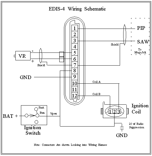
my ecu is wired in pretty much as std cosworth one, but with the addition of the edis 4 that is wired up like so
pin 1 edis to cos ecu pin 4 (CPS)
pin 2 edis to rev counter
pin 3 edis to cos ecu pin 25 (ign module)
pin 4 edis to cos ecu pin 24 (ign module)
pin 5 edis to brown/red wire to cps
pin 6 edis to white/red wire to cps
pin 7 edis shield
pin 8 edis to cos ecu pin 20 (ecu switched live)
pin 9 edis to cos ecu pin 19 (GND)
pin 10 edis to black/orange wire for coil A on coilpack
pin 11 edis blank
pin 12 edis to green/black wire coil B
these are the diagrams for the edis 4 module
S.E.C.S S8 ECU CONNECTIONS (COSWORTH VERSION)
=============================================
PIN ORIGINAL ECU S8 (IF DIFFERENT)
-------------------------------------------------------------------------
1 POWER GROUND
2 LAMBDA SENSOR INPUT
3 CRANK SENSOR GROUND
4 CRANK SENSOR INPUT
5 PHASE SENSOR GROUND
6 KNOCK SENSOR GROUND / USER OUTPUT 2
7 PURGE VALVE / USER OUTPUT 1 - WATER INJECTION
8 DIAGNOSTIC SOCKET / INJECTOR 5
9 VREF MONITOR / USER INPUT 1
10 POWER RELAY
11 VREF NEGATIVE
12 GENERAL OUTPUT / WARNING LAMP OUTPUT
13 OCTANE ADJUST / INJECTOR 6
14 OCTANE ADJUST / INJECTOR 7
15 MAP SENSOR INPUT
16 BOOST VALVE
17 THROTTLE POSITION
18 INJECTOR 4
19 POWER GROUND
20 POSITIVE SUPPLY
21 - / TACHO DRIVE OUTPUT
22 KNOCK SENSOR INPUT / USER INPUT 2
23 PHASE SENSOR INPUT
24 IGNITION TRIGGER GROUND
25 IGNITION TRIGGER OUTPUT / IGNITION 1 TRIGGER OUTPUT
26 - / IGNITION 2 TRIGGER OUTPUT
27 DIAGNOSTIC SOCKET / INJECTOR 8
28 FUEL PUMP RELAY
29 COOLANT SENSOR
30 VREF POSITIVE
31 CHARGE AIR SENSOR
32 INJECTOR 2
33 INJECTOR 3
34 IDLE SPEED VALVE
35 INJECTOR 1
my ecu is wired in pretty much as std cosworth one, but with the addition of the edis 4 that is wired up like so
pin 1 edis to cos ecu pin 4 (CPS)
pin 2 edis to rev counter
pin 3 edis to cos ecu pin 25 (ign module)
pin 4 edis to cos ecu pin 24 (ign module)
pin 5 edis to brown/red wire to cps
pin 6 edis to white/red wire to cps
pin 7 edis shield
pin 8 edis to cos ecu pin 20 (ecu switched live)
pin 9 edis to cos ecu pin 19 (GND)
pin 10 edis to black/orange wire for coil A on coilpack
pin 11 edis blank
pin 12 edis to green/black wire coil B
these are the diagrams for the edis 4 module
Last edited by Fudgey; 21-08-2009 at 08:37 PM.
21-08-2009, 08:45 PM
#1153
i think my problem could be with the edis pins 3 and 4 for the ecu ground and trigger as i dont think the ecu is seeing the cps.
but i do get spark, however chip says that the edis will go into limp home mode and fire at 10deg btdc so the edis at least is picking up on the cps.
but i do get spark, however chip says that the edis will go into limp home mode and fire at 10deg btdc so the edis at least is picking up on the cps.
23-08-2009, 10:40 PM
#1154
right, been out fucking about for a few hours tonight and buzzed out the loom/ecu plug/ and edis again...
and found that pin 19 of the cos ecu was NOT grounded. so stripped the tape off the loom and traced the wire. its went to an eylet that ryan had crimped on. well, the wire was still in the heatshrink... but was not connected...
so i connected it up to earth, retaped and refitted the loom. on the very first crank it spluttered... but nothing still
and after re-re-re-re-reading the wiring diagrams i do have to work from, i noticed that pin of the ecu, the cps ground is NOT connected, so have just been out and stipped the loom plug apart again, and sure enough the wire is not connected to anything. so surely the ecu needs a ground for the cps otherwise its not seeing a circuit....
tomorrow it will do this as i have already had a blocking off the wife for trying to start it at 10.45pm ::cry
fingers crossed as if its not that, then ill more than likely be buying a DTA ecu!
26-08-2009, 05:21 PM
#1158
Advanced PassionFord User
cheers paul