
Minimum cossie head thickness????

just finding my feet
Joined: May 2003
Posts: 41,052
Likes: 2
From: Im behind you
With YB's people worry too much
with a N?A runabout ya run it on the cheepest fuel ya can buy, check the oil when the little oil check light comes on when taking corners

with a cossie if theres a funny smell out side in the country ya pull over and call the AA out to be told its the farm over yonder


Too many posts.. I need a life!!
Joined: May 2004
Posts: 925
Likes: 0
From: in the garage fixing yet another oil leak
stu / karl
early cosworth group a 2wd pistons pa1079/6.2cr i think, had only very small squish assisting raised area on top. also they stopped about a mile short of the block face. whats going on here then, does a lower static cr mean less squish required?
excellent tread BTW
early cosworth group a 2wd pistons pa1079/6.2cr i think, had only very small squish assisting raised area on top. also they stopped about a mile short of the block face. whats going on here then, does a lower static cr mean less squish required?
excellent tread BTW

I've found that life I needed.. It's HERE!!


Joined: May 2003
Posts: 1,144
Likes: 9
Originally Posted by frog
Here's how I understand it...
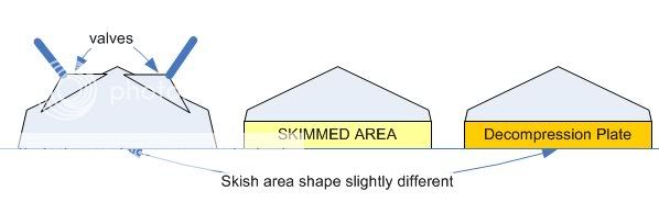
In the picture above, the decomp. plate only replaces the same amount of material that was removed by the skim(s).
However, because the walls of the plate are vertical, the squish area has changed shape.
Over to you Stu...
In the picture above, the decomp. plate only replaces the same amount of material that was removed by the skim(s).
However, because the walls of the plate are vertical, the squish area has changed shape.
Over to you Stu...

The red blobs on the leftmost diagram show the squish area, as the piston travels up the bore, the mixture is guided towards the centre of the combustion area. Now if you skim the head alot (middle diagram) or remove the squish area, there is alot less (sometimes nothing) squish area to guide the mixture to the centre of the combustion area. Adding a decompressin plate does nothing to aid this, as it is just an extension of the bore, it makes more space between the top of the piston and the cylinder head, but doesn't put back your squish area

PassionFords Creator
iTrader: (12)
Joined: May 2003
Posts: 28,824
Likes: 95
From: Blackpool, UK Destination: Rev limiter
Originally Posted by frog
When you add the plate in picture 3, you actually RAISE the head by an amount.
Does that help?
Maybe if you see where the squish area is on a YB cylinder head?
0-60 in 17 seconds (eek)
Joined: Apr 2004
Posts: 6,717
Likes: 0
From: Berkshire
wes, I agree 100% with you, your drawing is indeed more accurate and representative.
Now, if the decomp. plate reproduced the slope (As it was suggested above), would that be ok ?
As for worrying... I worry that if my engine blows up I will have to spend ����'s putting it back together, so I'd rather make sure it's as good as I can get it whenever it's in pieces.
If that means a new head, rather than taking chances with 16 valves or holes in pistons, a new head is the cheaper long term alternative - it's not worrying, it's financial planning...
I am actually in the process of putting my other half's car back together, and have two heads that are both below min. thickness... (hence my keen interest in this post ). Now do I take a chance with either and cross fingers, or, do I fix it properly now ???
Now, if the decomp. plate reproduced the slope (As it was suggested above), would that be ok ?
As for worrying... I worry that if my engine blows up I will have to spend ����'s putting it back together, so I'd rather make sure it's as good as I can get it whenever it's in pieces.
If that means a new head, rather than taking chances with 16 valves or holes in pistons, a new head is the cheaper long term alternative - it's not worrying, it's financial planning...
I am actually in the process of putting my other half's car back together, and have two heads that are both below min. thickness... (hence my keen interest in this post
0-60 in 17 seconds (eek)
Joined: Apr 2004
Posts: 6,717
Likes: 0
From: Berkshire
We did all come back to this together didn't we ? Had enough of the muppet room for the evening ?
100% with you here.
what if you raise it by the X amount you took off above ? That's what I don't really get.
Only thing that's clear in my mind is that the physical shape of the bit you take off when you skim is not the same as that of the decomp. plate.
Originally Posted by Stu @ M Developments
in reality all you will have done is dropped the whole head down "X"amount.
Originally Posted by Stu @ M Developments
When you add the plate in picture 3, you actually RAISE the head by an amount.
Only thing that's clear in my mind is that the physical shape of the bit you take off when you skim is not the same as that of the decomp. plate.

Too many posts.. I need a life!!
Joined: May 2004
Posts: 788
Likes: 4
From: shropshire
Originally Posted by Karl
PJ,
The method I use involves stress relieving the head during the welding process as well as having the head pre heated(I don't want to say what I do as thats giving the game away) but it results in a very hard head face and is totally reliable.
The method I use involves stress relieving the head during the welding process as well as having the head pre heated(I don't want to say what I do as thats giving the game away) but it results in a very hard head face and is totally reliable.
I weld the cylinder bores on 2 stroke cylinders prior to the surface being Re plated ( Ceramic coating) and know only to well how this affects the strength of the substrate alloy.
I've found that life I needed.. It's HERE!!
Joined: May 2003
Posts: 1,144
Likes: 9
Originally Posted by Stu @ M Developments
Jees, we all came back at once 

but also
Originally Posted by frog
Now, if the decomp. plate reproduced the slope (As it was suggested above), would that be ok ?
As for worrying... I worry that if my engine blows up I will have to spend ����'s putting it back together, so I'd rather make sure it's as good as I can get it whenever it's in pieces.
If that means a new head, rather than taking chances with 16 valves or holes in pistons, a new head is the cheaper long term alternative - it's not worrying, it's financial planning...
I am actually in the process of putting my other half's car back together, and have two heads that are both below min. thickness... (hence my keen interest in this post). Now do I take a chance with either and cross fingers, or, do I fix it properly now ???
As for worrying... I worry that if my engine blows up I will have to spend ����'s putting it back together, so I'd rather make sure it's as good as I can get it whenever it's in pieces.
If that means a new head, rather than taking chances with 16 valves or holes in pistons, a new head is the cheaper long term alternative - it's not worrying, it's financial planning...
I am actually in the process of putting my other half's car back together, and have two heads that are both below min. thickness... (hence my keen interest in this post
If the head has been extensivley worked on then i'd ask Karl about the welding and maching to get it back to original thickness, if it's a bog standard head (apart from the skimming) then again either talk to Karl or source 2nd hand ones, and keep the skimmed ones for a rainy day (when all the good yb heads run out
)
PassionFords Creator
iTrader: (12)
Joined: May 2003
Posts: 28,824
Likes: 95
From: Blackpool, UK Destination: Rev limiter
Well lets just simplify it and say its hard enough to get a YB to seal with one fooking head gasket, let alone two of em.
Anyone care about squish given that comment?
Anyone care about squish given that comment?
PassionFord Post Troll
Joined: Jun 2003
Posts: 2,942
Likes: 0
BRILLIANT thread!
Stu - you say that you get a better burn if the fuel goes to the centre of the piston therefore create a bowl in the piston rather then skimming the tops of the pistons so would it be worth doing this to a mahle in a cvh engine rather then skimming them flat!?
Karl - can you also weld onto a cvh head too? also are we still on for saturday please say yes
Stu - you say that you get a better burn if the fuel goes to the centre of the piston therefore create a bowl in the piston rather then skimming the tops of the pistons so would it be worth doing this to a mahle in a cvh engine rather then skimming them flat!?
Karl - can you also weld onto a cvh head too? also are we still on for saturday


i have reclaimed head by various methods , but would be seriously sceptical about having the face completely welded and re machined simply because of hardness issues thats not to say it cannot be done , karl, you must have done this succesfully otherwise you wouldnt mention it , just one of those things i wouldnt have done till id tested it myself 
though i must admit ive rewelded stuff and machined it back to good as new that alot of people said was scrap
thats not to say it cannot be done , karl, you must have done this succesfully otherwise you wouldnt mention it , just one of those things i wouldnt have done till id tested it myself though i must admit ive rewelded stuff and machined it back to good as new that alot of people said was scrap
1) rarther than a decomp plate, would one of those copper head gaskets (is it ferriday make them?  ) be a viable alternative, as there is no gasket as such, and the squish area could be built back in by shaping the gasket?
2) does the squish area on a 2wd and 4x4 head vary? I know they are diff in combustion chamber design, ie pent roof and rounded.
3) do valve cutouts in pistons promote hotspots and det?
awsome topic, keep the tech info coming best read i've had 4 ages
2) does the squish area on a 2wd and 4x4 head vary? I know they are diff in combustion chamber design, ie pent roof and rounded.
3) do valve cutouts in pistons promote hotspots and det?
awsome topic, keep the tech info coming
0-60 in 17 seconds (eek)
Joined: Apr 2004
Posts: 6,717
Likes: 0
From: Berkshire
Originally Posted by RWD_cossie_wil
1) rarther than a decomp plate, would one of those copper head gaskets (is it ferriday make them? ) be a viable alternative, as there is no gasket as such, and the squish area could be built back in by shaping the gasket?
-Copper headgasket, only up to a certain thickness.
-Decompression plate, thicker than H/G, but then you need a "normal" i.e. non-copper head gasket to go with.
Their copper headgasket has fire rings (or something else) machined in it, so they can't make it too thick.
PassionFords Creator
iTrader: (12)
Joined: May 2003
Posts: 28,824
Likes: 95
From: Blackpool, UK Destination: Rev limiter
I think people are still not following what part of the head makes up the squish here, but i cant think of a good way to put it into words.... 

PassionFord Post Whore!!
Joined: May 2003
Posts: 3,795
Likes: 0
From: Wiltshire UK
Originally Posted by Stu @ M Developments
I think people are still not following what part of the head makes up the squish here, but i cant think of a good way to put it into words....
I thought my dodgy sketch may make it clearer..
if you have a spacer plate with a 90-odd millimetre circular bore (ie to the gasket line on the picture), the shaded areas of the head (the squish area) will be spaced apart from the block face (and obviously the piston crown)

PassionFord Post Whore!!
Joined: May 2003
Posts: 3,795
Likes: 0
From: Wiltshire UK
Originally Posted by St3V3_C
I'm understanding that Rich
So, if the plate is made to include the bits you have shaded, rather than just round holes, does that make it OK?
(back to what I originally asked )
So, if the plate is made to include the bits you have shaded, rather than just round holes, does that make it OK?
(back to what I originally asked
)yeah, in theory, but the unsupported area would just not be stable enough IMO.. and we are then missing the point - the primary problem isn't a 'dangerous' compression issue (makes around 0.2 CR increase at minimum thickness or thereabouts) but rather the issue of breaking into the valve seat inserts.. so the plate would not help that at all..

20K+ Super Poster.
Joined: May 2003
Posts: 23,377
Likes: 0
Here's a question...........
If the head has been skimmed to it's limit, does this mean that where the squish area was dome shaped, but now has a flat step at the valve seat edge, that yo're gonna be more prone to hot spots in that area?
If the head has been skimmed to it's limit, does this mean that where the squish area was dome shaped, but now has a flat step at the valve seat edge, that yo're gonna be more prone to hot spots in that area?
PassionFord Post Whore!!
Joined: May 2003
Posts: 3,795
Likes: 0
From: Wiltshire UK
Originally Posted by RichardPON
Here's a question...........
If the head has been skimmed to it's limit, does this mean that where the squish area was dome shaped, but now has a flat step at the valve seat edge, that yo're gonna be more prone to hot spots in that area?
If the head has been skimmed to it's limit, does this mean that where the squish area was dome shaped, but now has a flat step at the valve seat edge, that yo're gonna be more prone to hot spots in that area?
How do you mean 'dome shaped'?
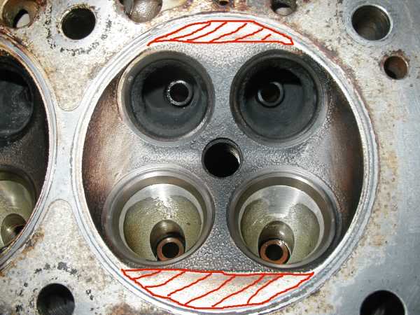
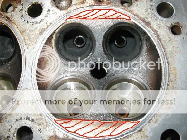
The squish area on the head is flat in both cases, the skim makes very little difference to the squish area, it gets marginally wider towards the valve seats as you machine into the sloped chamber wall, but very little changes..
138.8mm:
139.2mm:
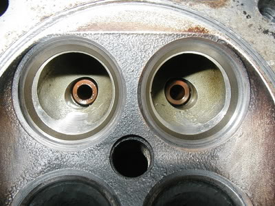
you can see the flat squish area above the inlet valves in these pictures is almost identical..

PassionFord Post Troll
Joined: Sep 2004
Posts: 2,795
Likes: 0
From: Next to my frog...
I think I followed all that and finally managed to understand the squish thingy..
Have made a drawing in power point... so asking the man to covert it into a .jpeg or .gif to post it...
Have made a drawing in power point... so asking the man to covert it into a .jpeg or .gif to post it...
PassionFord Post Troll
Joined: Sep 2004
Posts: 2,795
Likes: 0
From: Next to my frog...
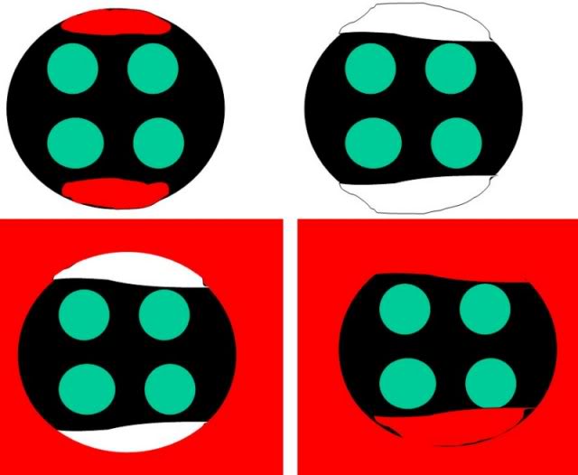
I know its quite a bad drawing but the way I see it is the first drawing is a "normal" head, never been skimmed, with red area being the squish area.
Second drawing, head been skimmed and the white bit is the part of the squish that has been "lost" in the skim. Am I right there?
Third is with a decomp. plate added (red). As the plate is around the valve area only and does not replace the squish that is missing(white area), the head has just been raised... still ok?
Fourth is I guess the sort of plate that would be needed to get the squish back to normal....
Am I almost right or shall I get back to my kitchen???

I've found that life I needed.. It's HERE!!
Joined: May 2003
Posts: 1,144
Likes: 9
Yes you've got it pretty much right, however the decomp plate shaped to the squish area will require 2 headgaskets, so there will also be a space between the plate and the head, which would lead to even futher problems!
PassionFord Post Whore!!
Joined: May 2003
Posts: 3,795
Likes: 0
From: Wiltshire UK
Originally Posted by wes
Yes you've got it pretty much right, however the decomp plate shaped to the squish area will require 2 headgaskets, so there will also be a space between the plate and the head, which would lead to even futher problems!
PassionFord Post Troll
Joined: Sep 2004
Posts: 2,795
Likes: 0
From: Next to my frog...
Originally Posted by wes
Yes you've got it pretty much right, however the decomp plate shaped to the squish area will require 2 headgaskets, so there will also be a space between the plate and the head, which would lead to even futher problems!
As Greg (my other half) said before, we're in need of a working head. So really, what's the best thing to do? Get a new head now while they are still available or try to have ours reconditioned?....
Because from what I understand, there is no way once the head has been skimmed to actually get it back to absolute "normal" like it was when new, whichever solution is chosen. I guess that would alsomean the car would need to be remapped then to compensate for the "loss of squish"...
How would that affect the performance and reliability (or lack of...
) of the car?
PassionFord Post Whore!!
Joined: May 2003
Posts: 3,795
Likes: 0
From: Wiltshire UK
Originally Posted by wes
Which other method of sealing could you use that would not leave a gap between the plate squish sections and the head?
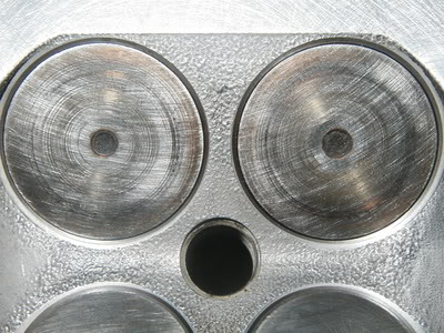
essentially the same as we used here (although we did the other way up, plate to block and gasket between plate and head):
http://www.rsrich.force9.co.uk/zetec...090014_jpg.htm
http://www.rsrich.force9.co.uk/zetec...090015_JPG.htm
I've found that life I needed.. It's HERE!!
Joined: May 2003
Posts: 1,144
Likes: 9
If you can get hold of a brand new head then that is the best starting point, when i had my engine built i bought a new one, it was then machined to grp A spec, i didn't want to spend the money on the work to be done and then find the head would be scrap if it needed one skim at any point in the future. Next best option is to source a 2nd hand head that hasn't been skimmed ever.
You really should speak to Karl 1st though about the welding and refinishing, as a new head is about �1000 - �1500 + VAT!
You really should speak to Karl 1st though about the welding and refinishing, as a new head is about �1000 - �1500 + VAT!
0-60 in 17 seconds (eek)
Joined: Apr 2004
Posts: 6,717
Likes: 0
From: Berkshire
Has anyone seen the little insert on page 10 of Performance Ford this month (april 2005) ?
There's something in there about Ferriday engineering being able to CNC machine the head's combustion chamber for a head that's been skimmed.
Can someone who knows what they are talking about check this for me please, better still, give them a call (mike 01785 621 710) and find out what the deal is ?
There's no point me calling him, whatever he'll tell me will sound like gospel cos I haven't got a clue
CheeRS guys.
 for the morning crew.
PassionFord Post Whore!!
Joined: May 2003
Posts: 3,795
Likes: 0
From: Wiltshire UK
just as a reminder... may be useful to get back to an early stage of the discussion that we've maybe strayed from..
-------------------------------------------
Quote from Stu:
Brad,
Its a misconception that the head becomes "Too thin, or weak" and also that its about the altered "Compression Ratio"
The issue is the area around the valve seat becomes dangerously thin after 138.68mm.
-------------------------------------------
the compression change isn't so much the issue as the machined face breaking into the valve seats... (compression increases to about 8.2:1 for a 0.5mm material loss).
spacer plates and chamber machining won't change this at all..
-------------------------------------------
Quote from Stu:
Brad,
Its a misconception that the head becomes "Too thin, or weak" and also that its about the altered "Compression Ratio"
The issue is the area around the valve seat becomes dangerously thin after 138.68mm.
-------------------------------------------
the compression change isn't so much the issue as the machined face breaking into the valve seats... (compression increases to about 8.2:1 for a 0.5mm material loss).
spacer plates and chamber machining won't change this at all..
0-60 in 17 seconds (eek)
Joined: Apr 2004
Posts: 6,717
Likes: 0
From: Berkshire
Originally Posted by richm
just as a reminder... may be useful to get back to an early stage of the discussion that we've maybe strayed from..
Originally Posted by richm
-------------------------------------------
Quote from Stu:
Brad,
Its a misconception that the head becomes "Too thin, or weak" and also that its about the altered "Compression Ratio"
The issue is the area around the valve seat becomes dangerously thin after 138.68mm.
-------------------------------------------
the compression change isn't so much the issue as the machined face breaking into the valve seats... (compression increases to about 8.2:1 for a 0.5mm material loss).
Would live mapping be required to counteract the increase in compression ratio ?
PassionFord Post Whore!!
Joined: May 2003
Posts: 3,795
Likes: 0
From: Wiltshire UK
Originally Posted by frog
Rich, I agree the discussion is very interesting from a technical point of view, but I think a few valid points were made regarding resurrecting otherwise scrap heads. This is probably of significant interest to quite a few people since decent quality heads are rarer than hen's teeth.
although IMO Karls welding reclamation is the only one relevant due to the seat exposure issues, which any form of decompression plate or chamber machining will not address.