home made fault code reader, how to make one
 21-09-2007, 12:34 AM
#1
PassionFord Post Whore!!
Thread Starter
Join Date: Jul 2004
Location: isle of wight (K.O.P 2006 mother fucker!)
Posts: 4,276
Likes: 0
Received 0 Likes
on
0 Posts
i found this site ages ago and due to reasons and forgetting never got round to doing it, im sure i put a post up about it but the search cant find it.
anyway, ive got all the bits together now and i sahll start to make it this week
the chip it self has to be got from the designer, its �12 posted for the chip, and the componants can differ in cost depending where you get them, i got most from rapid online and 2 bits from maplins due to rapid being out of stock, and in total its cost me about �38.50 in bits.
if you have to buy solder and a soldering iron etc then it will cost you more, and amore again if you get from maplins.
anyway, the bits

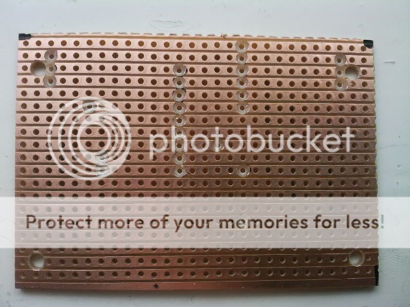
i marked out and preped the strip board tonight quick while i stood in the shed having a fag but the main bits will start asap.
the site the FCR can be found on is here
http://www.graynada.co.uk/
the site gives you the following
parts list with part numbers both maplins and rapid online
full detailed instructions with pictures for building it
full instrcutions how to use it
and a few months back, a pc interface software was added (free download)
this reader will give error messages/codes but not in sill flashing led light style.
i will update as i build, then i need someone with a car with a fault to test it on, jon hows the rs mate?
oh btw, it doesnt just cover a rs, it covers a range of fords, i belive 3 and 5 pin ports
23rd sep 2007
right, to save it being all ver the place i will add here on the first post.
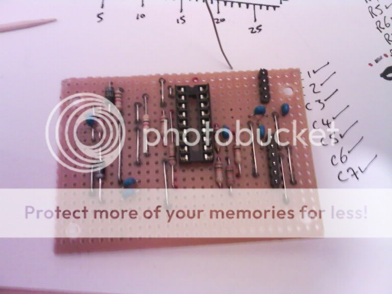
had a bit of time yesterday, so got on with it, had to make a trip to mapins as i found rapid had sent me a 20 pin DIL socket not a 18 , still no matter, burnt more fuel than the 75p i spen getting it and 2 more led's
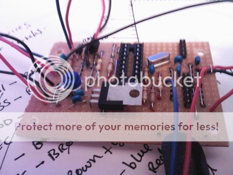
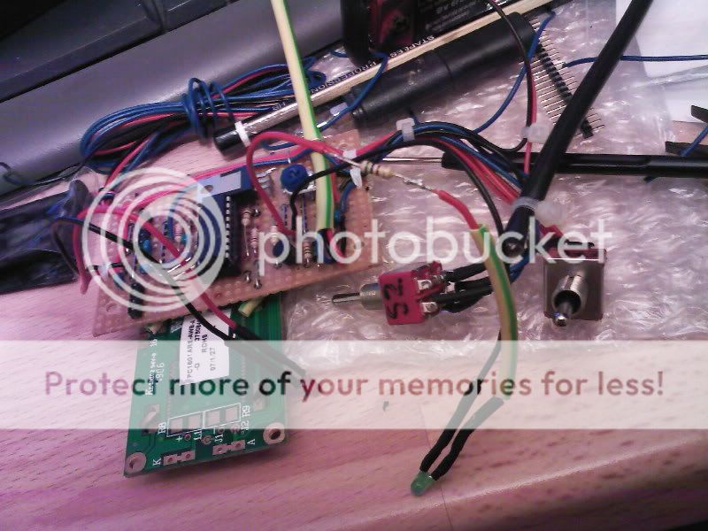
anyway, altough there are pictures on the site, i will add some here as a visual progress report, not for instuction on how to make one.
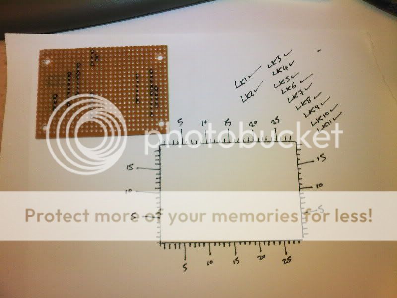
i did draw round the board and mark out numbers etc to make it easier to locate where to put stuff, i always double checked before soldering etc and i even made a mistake and marked a resistor 1 hole short, but i hadnt bent the legs so no harm done, just shows its important to double check.
anyway, enough spill, pictures for now, im gunna crack on with it now, i wont finish it as i still need a plug for the car as i can find the one i had set aside


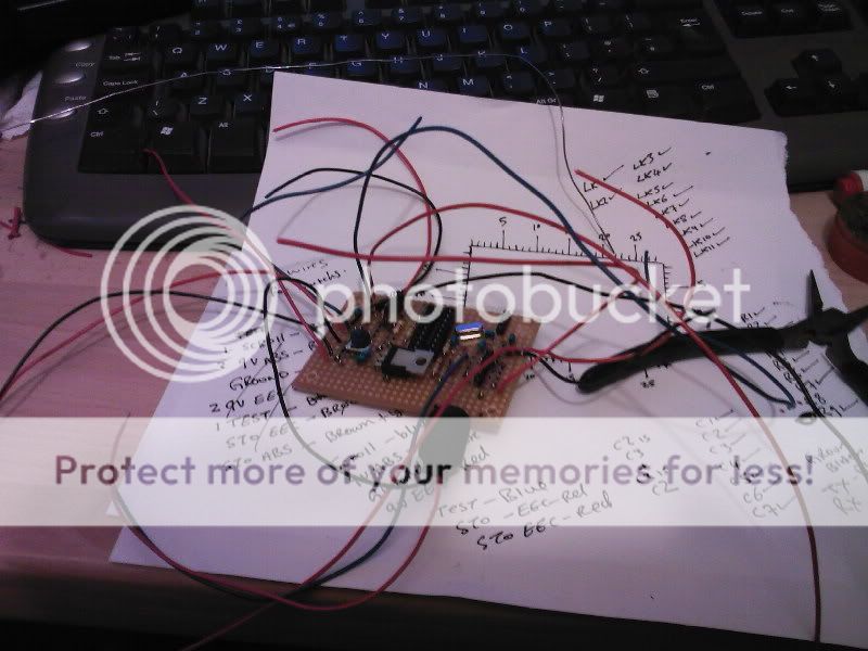
24th, not had much time to do anything.
got stuck on a couple of wires, not sure where they go on the switch so have asked the designer ifwhat i think is right,
pics so far
30/9/07
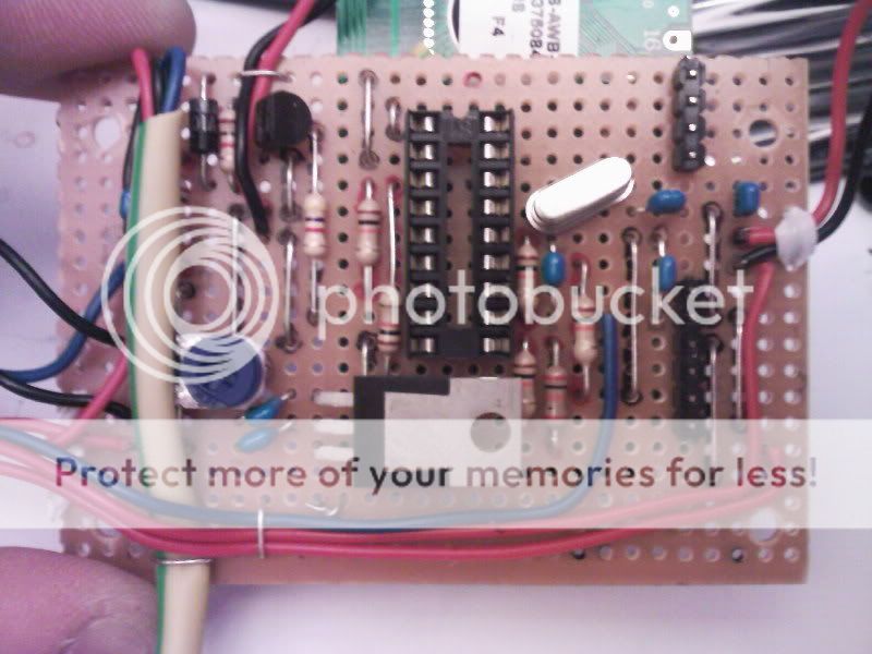
i finished this reader last week, but it failed to work.
not having much time and really not knowing where to start i emailed the designer (graham) graham was massive help, i checked all i could and all the bits he said and it narrowed it down to a LED, it turns out maplins had given me the wrong LED's :x and thius it was drawing all the power and nothing else was working.
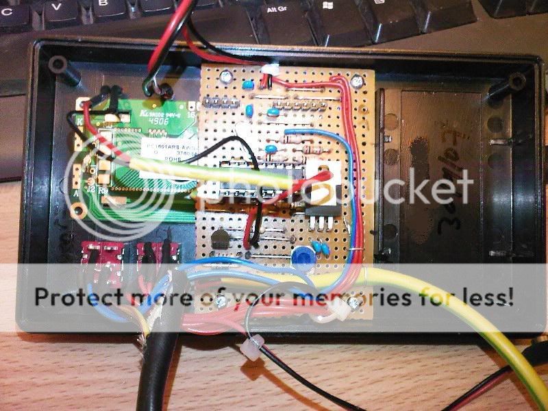
anyway, i had some time to mess about with it today so i tested it all before fitting the screen again, i had to remove it to check for shorts under it, i knew there wasnt any but you got to dopuble check these things, but it was tested and it allo worked so the screen was soldered back on.
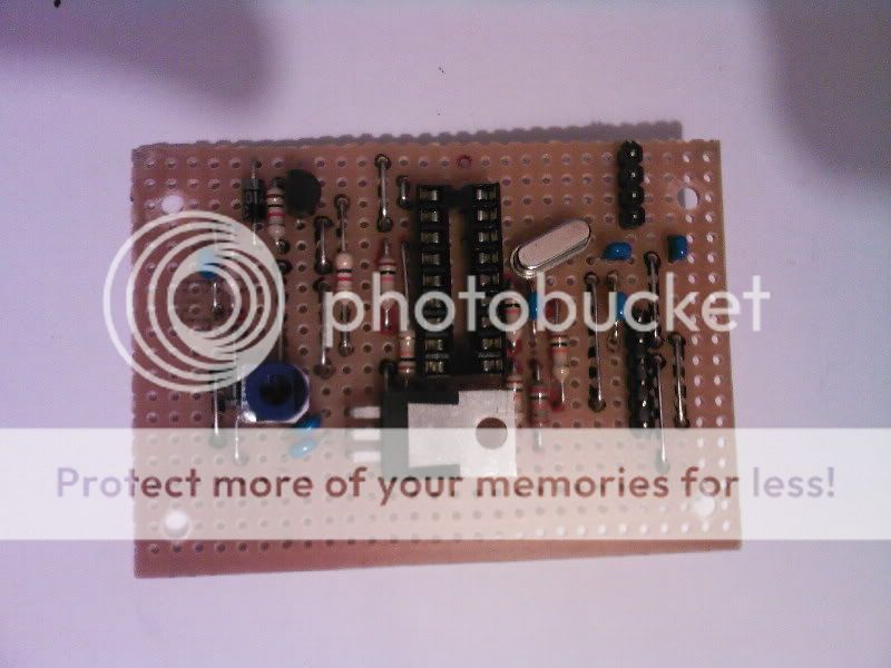
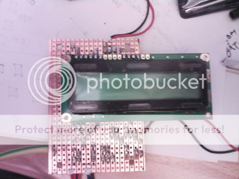
those of you that have looked at grahams site and read the build instructions will see my led's are not as graham has done, i wanted them both at the top above the screen so i soldered wires to them and fitted them that way, and due to maplins giving me the wrong LED's it made it that little bit easier to fit a in libne resistor to the green one.
the red just flashes on test so graham tells me so that can stay as it is but the green is resisted now and it all still works fine.
pictures of it now, the case was a bit of a nigth mare, i messured it out wrong and with out double checking it (which isnt like me)i chain drilled it, only to check after and fine i went over a bit no matter, i plan on putting a coloured plastic over the front with the writing bits on and it will cover it but then again im thinking of like a frame round it too so it dont matter what it looks like as long as it works

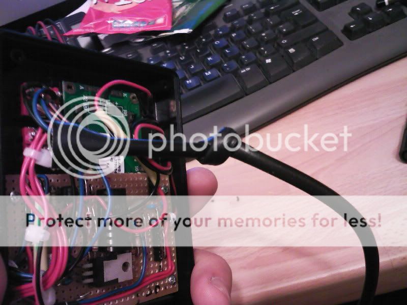
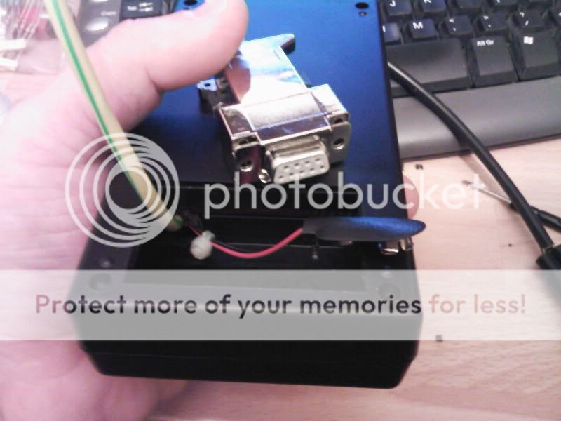
pc plug is too big to fit as well as battery so got to doctor that

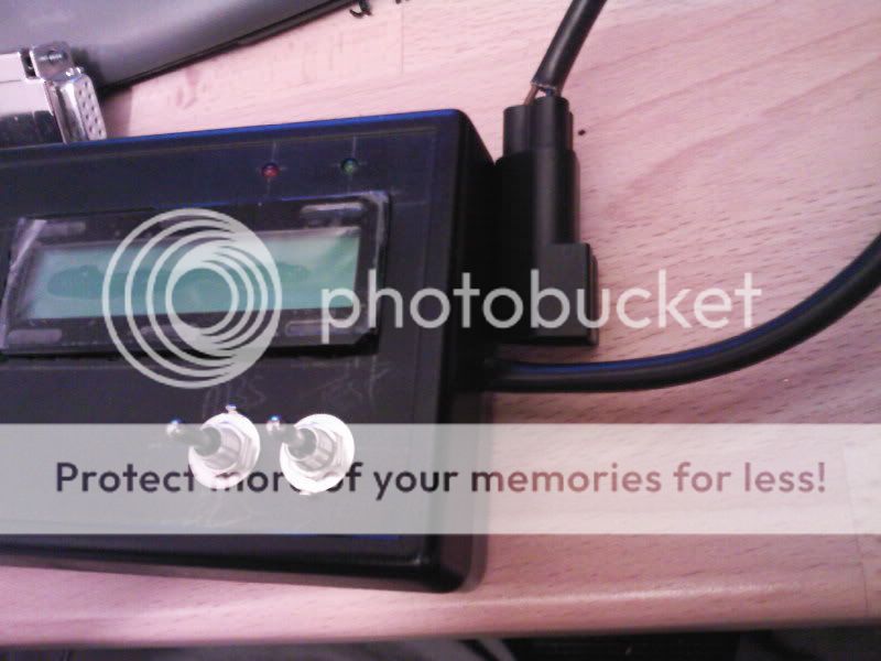
and it working


anyway, ive got all the bits together now and i sahll start to make it this week
the chip it self has to be got from the designer, its �12 posted for the chip, and the componants can differ in cost depending where you get them, i got most from rapid online and 2 bits from maplins due to rapid being out of stock, and in total its cost me about �38.50 in bits.
if you have to buy solder and a soldering iron etc then it will cost you more, and amore again if you get from maplins.
anyway, the bits
i marked out and preped the strip board tonight quick while i stood in the shed having a fag but the main bits will start asap.
the site the FCR can be found on is here
http://www.graynada.co.uk/
the site gives you the following
parts list with part numbers both maplins and rapid online
full detailed instructions with pictures for building it
full instrcutions how to use it
and a few months back, a pc interface software was added (free download)
this reader will give error messages/codes but not in sill flashing led light style.
i will update as i build, then i need someone with a car with a fault to test it on, jon hows the rs mate?
oh btw, it doesnt just cover a rs, it covers a range of fords, i belive 3 and 5 pin ports
23rd sep 2007
right, to save it being all ver the place i will add here on the first post.
had a bit of time yesterday, so got on with it, had to make a trip to mapins as i found rapid had sent me a 20 pin DIL socket not a 18
anyway, altough there are pictures on the site, i will add some here as a visual progress report, not for instuction on how to make one.
i did draw round the board and mark out numbers etc to make it easier to locate where to put stuff, i always double checked before soldering etc and i even made a mistake and marked a resistor 1 hole short, but i hadnt bent the legs so no harm done, just shows its important to double check.
anyway, enough spill, pictures for now, im gunna crack on with it now, i wont finish it as i still need a plug for the car as i can find the one i had set aside
24th, not had much time to do anything.
got stuck on a couple of wires, not sure where they go on the switch so have asked the designer ifwhat i think is right,
pics so far
30/9/07
i finished this reader last week, but it failed to work.
not having much time and really not knowing where to start i emailed the designer (graham) graham was massive help, i checked all i could and all the bits he said and it narrowed it down to a LED, it turns out maplins had given me the wrong LED's :x and thius it was drawing all the power and nothing else was working.
anyway, i had some time to mess about with it today so i tested it all before fitting the screen again, i had to remove it to check for shorts under it, i knew there wasnt any but you got to dopuble check these things, but it was tested and it allo worked so the screen was soldered back on.
those of you that have looked at grahams site and read the build instructions will see my led's are not as graham has done, i wanted them both at the top above the screen so i soldered wires to them and fitted them that way, and due to maplins giving me the wrong LED's it made it that little bit easier to fit a in libne resistor to the green one.
the red just flashes on test so graham tells me so that can stay as it is but the green is resisted now and it all still works fine.
pictures of it now, the case was a bit of a nigth mare, i messured it out wrong and with out double checking it (which isnt like me)i chain drilled it, only to check after and fine i went over a bit
pc plug is too big to fit as well as battery so got to doctor that
and it working

 22-09-2007, 10:25 AM
#3
PassionFord Post Whore!!
Thread Starter
Join Date: Jul 2004
Location: isle of wight (K.O.P 2006 mother fucker!)
Posts: 4,276
Likes: 0
Received 0 Likes
on
0 Posts
yes mate it does, theres a software interface on the site too.
i shall add the link to the guys website to the first post in a mo.
i shall add the link to the guys website to the first post in a mo.


 . how hard is it to make it work
23-09-2007, 03:31 PM
. how hard is it to make it work
23-09-2007, 03:31 PM
#7
PassionFord Post Whore!!
Thread Starter
Join Date: Jul 2004
Location: isle of wight (K.O.P 2006 mother fucker!)
Posts: 4,276
Likes: 0
Received 0 Likes
on
0 Posts
ive nopt finished it yet mate, im just about to add a update
all updates will be added to the first post
all updates will be added to the first post
Trending Topics

Thread
Thread Starter
Forum
Replies
Last Post
oilman
Trader Parts for Sale.
5
30-08-2015 08:37 AM
Stu @ M Developments
General Car Related Discussion.
41
21-08-2015 06:47 AM