
Further Throttle Position Sensor Troubles - PROBLEM SOLVED!


Thread Starter
PassionFord Post Whore!!
Joined: Jun 2003
Posts: 3,744
Likes: 0
From: Exeter
Hi guys
See bottom of the thread for the solution ......
I have reposted, as the other thread went a little off topic! (my fault)
I tried the voltage test that was suggested, and it the multimeter read 4.94 volts between pins 11 and 17. Unfortuntately it doesnt vary much with more or less throttle.
What we know -
1. I have just changed from a L6 to a L8 ECU.
2. I changed the TPS to a PF09 and swapped the outer wires on the sensor, as instructed.
So is the sensor knackered? Or am I testing the wrong pins?
Would I know on the running of the engine if the TPS was knackered?
HELP?
Thanks guys
JJ
Thread Starter
PassionFord Post Whore!!
Joined: Jun 2003
Posts: 3,744
Likes: 0
From: Exeter
Right - results as follows;
0 Throttle 1/2 Throttle 1 Throttle
30 and 17--------------0-----------------0---------------0
30 and 11-------------4.95-------------4.95------------4.95
11 and 17-------------4.95-------------4.95------------4.95
I am guessing that this isnt good
JJ
0 Throttle 1/2 Throttle 1 Throttle
30 and 17--------------0-----------------0---------------0
30 and 11-------------4.95-------------4.95------------4.95
11 and 17-------------4.95-------------4.95------------4.95
I am guessing that this isnt good
JJ
No, thats not good, its just not working at all.
Possibly a broken wire on pin 17 between it and the ecu, or possibly you swapped the wrong wires over, if its not those, its the sensor fucked, I could meet you for a pint and try swapping it for mine if you want?
Possibly a broken wire on pin 17 between it and the ecu, or possibly you swapped the wrong wires over, if its not those, its the sensor fucked, I could meet you for a pint and try swapping it for mine if you want?
Actually, i dont think it can be a broken wire on pin 17, as then it would be open circuit and read as 0 between it and pin 11.
So looks like the tps is knackered, but that seems highly unliklely.
Have you tried a resistance meter on the TPS itself?
Did you do these tests at the TPS end or the ECU end?
So looks like the tps is knackered, but that seems highly unliklely.
Have you tried a resistance meter on the TPS itself?
Did you do these tests at the TPS end or the ECU end?
Trending Topics
It IS the wrong way round actually I think Jim mate.
It should be 5v at pin 30, and he has 0 it would appear.
Try between pin 30 and ground JJ, and between pin 11 and ground, with both a resistance meter and a volt meter.
you should get
30 vs ground on volts = 5
30 vs ground on resist = >0
11 vs ground on volts = 0
11 vs ground on resist = 0
It should be 5v at pin 30, and he has 0 it would appear.
Try between pin 30 and ground JJ, and between pin 11 and ground, with both a resistance meter and a volt meter.
you should get
30 vs ground on volts = 5
30 vs ground on resist = >0
11 vs ground on volts = 0
11 vs ground on resist = 0


aka Turbosailorboy
iTrader: (5)
Joined: Apr 2005
Posts: 6,527
Likes: 21
From: Under the water.... .......in a nuclear submarine
Pin 17 is Black with a Red trace (TPS signal into ECU)
Pin 30 is Red (5 Volt feed into TPS from ECU)
Pin 11 is Brown with Green trace (Earth/Negative feed to TPS from ECU)
Note; Pin 11 also feeds the Air and Coolant temp sensors with an ECU earth supply as well as the TPS.
Pin 30 is Red (5 Volt feed into TPS from ECU)
Pin 11 is Brown with Green trace (Earth/Negative feed to TPS from ECU)
Note; Pin 11 also feeds the Air and Coolant temp sensors with an ECU earth supply as well as the TPS.
Thread Starter
PassionFord Post Whore!!
Joined: Jun 2003
Posts: 3,744
Likes: 0
From: Exeter
I will try -
Right results;
30 vs ground volts - 4.96
30 vs ground on resist - 0 (dont understand gauge, but didnt move)
11 vs ground on volts - 0
11 vs ground on resist - 08.7 (not sure on this one!)
When I apply throttle, none of the above figures change at all! They all remain constant
Strange that it is the wrong way round given that I specifically changed it. I changed the outer two wires - unless I put the socket on wrong way round (unlikely!)
JJ
If 30 vs ground is giving you 5v, thats correct.
30 vs ground = open circuit, thats correct
11 vs gorund = 0v, thats correct
11 vs ground = very small, thats correct
If its not changing between 30 and ground or 11 and ground when you apply throttle, thats correct.
Sounds like it might be the TPS is broken.
30 vs ground = open circuit, thats correct
11 vs gorund = 0v, thats correct
11 vs ground = very small, thats correct
If its not changing between 30 and ground or 11 and ground when you apply throttle, thats correct.
Sounds like it might be the TPS is broken.
Thread Starter
PassionFord Post Whore!!
Joined: Jun 2003
Posts: 3,744
Likes: 0
From: Exeter
Originally Posted by B9KOS
Pin 17 is Black with a Red trace (TPS signal into ECU)
Pin 30 is Red (5 Volt feed into TPS from ECU)
Pin 11 is Brown with Green trace (Earth/Negative feed to TPS from ECU)
Note; Pin 11 also feeds the Air and Coolant temp sensors with an ECU earth supply as well as the TPS.
Pin 30 is Red (5 Volt feed into TPS from ECU)
Pin 11 is Brown with Green trace (Earth/Negative feed to TPS from ECU)
Note; Pin 11 also feeds the Air and Coolant temp sensors with an ECU earth supply as well as the TPS.
Thanks matey - that is useful. So by my reckoning, the figure between 11 and 17 for voltage should at least vary between throttle positions. All is pointing to a faulty sensor at this point then!
OR - a bad connection between the TPS and the ECU on the wiring......
That said - if it was a bad wire, you would expect the default position to be 0v, not 5v
Originally Posted by JjCoDeX75
Thanks matey - that is useful. So by my reckoning, the figure between 11 and 17 for voltage should at least vary between throttle positions. All is pointing to a faulty sensor at this point then!
OR - a bad connection between the TPS and the ECU on the wiring......
That said - if it was a bad wire, you would expect the default position to be 0v, not 5v
OR - a bad connection between the TPS and the ECU on the wiring......
That said - if it was a bad wire, you would expect the default position to be 0v, not 5v
reading between 11 and 17 should change
reading between 30 and 17 should change
reading between 30 and 11 should NOT change
Is pin 17 at 5v when versus ground?
If so, thats either:
short between 17 and 30
fucked TPS
aka Turbosailorboy
iTrader: (5)
Joined: Apr 2005
Posts: 6,527
Likes: 21
From: Under the water.... .......in a nuclear submarine
Had a problem with my mates recently after we had the pins out of the plug. When we pushed the plug on it was pushing the pins back out 

Originally Posted by JjCoDeX75
So how does the car know when I go to WOT then?
Why is the car running well at all if the TPS is rodgered?
JJ
Why is the car running well at all if the TPS is rodgered?
JJ
It thinks you are at full throttle all the time if its seeing 5v
Only Stu could tell you how his chip behaves at WOT all the time.
I would expect it to:
over fuel off boost
never going into closed loop
but im guessing here mate, the closed loop entry criteria may only be set against RPM vs MAP and not versus TPS at all.

Banned
Joined: Jul 2003
Posts: 7,078
Likes: 0
Originally Posted by JjCoDeX75
So how does the car know when I go to WOT then?
Why is the car running well at all if the TPS is rodgered?
JJ
Why is the car running well at all if the TPS is rodgered?
JJ
* It is a dangerous condition to leave the TPS off, because IIRC Stu once commented on here that an engine could melt without the correct TPS signals reaching the ECU.
Thread Starter
PassionFord Post Whore!!
Joined: Jun 2003
Posts: 3,744
Likes: 0
From: Exeter
Hmmmmmm
This is concerning.
When I had the throttle on the bench, resistance deffo varied through the movement of the throttle - (this was disconnected from the loom etc)
I am incresingly concerned by the comments - I will probably take it to pieces again, and make sure that the connector is seated correctly etc.
Anyone know how to test the TPS when it is off the throttle body?
JJ
JJ
If you are free at the weekend, meet up with me, we can try swapping things about, my car will tell me if the TPS is working or not as I can see the actual value in degrees on my mapping software.
If you are free at the weekend, meet up with me, we can try swapping things about, my car will tell me if the TPS is working or not as I can see the actual value in degrees on my mapping software.
Thread Starter
PassionFord Post Whore!!
Joined: Jun 2003
Posts: 3,744
Likes: 0
From: Exeter
Originally Posted by Chip-3Door
JJ
If you are free at the weekend, meet up with me, we can try swapping things about, my car will tell me if the TPS is working or not as I can see the actual value in degrees on my mapping software.
If you are free at the weekend, meet up with me, we can try swapping things about, my car will tell me if the TPS is working or not as I can see the actual value in degrees on my mapping software.
I would like to , but I am in Newquay with wifey.
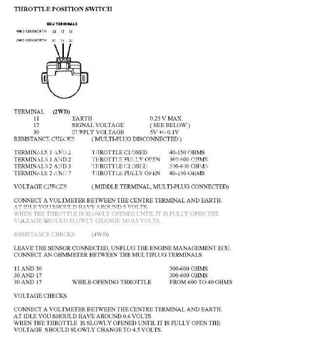
I have found the below in my Sierra Cosworth technical diagnosis information.....
Given the potential consequences, I am going to carry out full tests tonight.
Shame - I am going to have to learn to use a multimeter properly now to test resistance!!!!
JJ
Thread Starter
PassionFord Post Whore!!
Joined: Jun 2003
Posts: 3,744
Likes: 0
From: Exeter
Also, to add,
given that the volt out for the centre position is 4.95 at WOT, mine basically thinks it is permanently at WOT. Given this, it is more likely to be running rich, rather than lean! This should somewhat limit the damage to the engine.....
Discuss
JJ
given that the volt out for the centre position is 4.95 at WOT, mine basically thinks it is permanently at WOT. Given this, it is more likely to be running rich, rather than lean! This should somewhat limit the damage to the engine.....
Discuss
JJ
Originally Posted by JjCoDeX75
Also, to add,
given that the volt out for the centre position is 4.95 at WOT, mine basically thinks it is permanently at WOT. Given this, it is more likely to be running rich, rather than lean! This should somewhat limit the damage to the engine.....
Discuss
JJ
given that the volt out for the centre position is 4.95 at WOT, mine basically thinks it is permanently at WOT. Given this, it is more likely to be running rich, rather than lean! This should somewhat limit the damage to the engine.....
Discuss
JJ
you have a wideband dont you anyway mate?
Thread Starter
PassionFord Post Whore!!
Joined: Jun 2003
Posts: 3,744
Likes: 0
From: Exeter
Yes, though sensor is fucked - still waiting for new one to arrive.
I must admit, I wouldnt describe the throttle as sluggish though -
I am having what can technically be described as a bad sensor day!
JJ
I must admit, I wouldnt describe the throttle as sluggish though -
I am having what can technically be described as a bad sensor day!
JJ
Thread Starter
PassionFord Post Whore!!
Joined: Jun 2003
Posts: 3,744
Likes: 0
From: Exeter
B9KOS - You win the smug hat award!
It was exactly the same problem that you were having - the wires where they had been removed and replaced were being pushed out of the clip, and as such, the sensor was not being powered properly!
Lesson learnt.
Put in properly, and re-tested, and hey presto! All working fine!
Another lesson for all, if the Throttle switch aint working, the L8 defaults to 5v (ie WOT) This helps reduce engine damage in bad throttle situations!
Thats a bloody relief all things considered!
Now I may find out how efficient the closed loop system can be! I only hope that the over fuelling hasnt killed the brand spanking sensor!
JJ
Thread Starter
PassionFord Post Whore!!
Joined: Jun 2003
Posts: 3,744
Likes: 0
From: Exeter
Sorry to ressurect this one guys, but I have still a few issues relating to idle only.
TPS is now working, but the setup is not quite right. I note that the base voltage should be 0.6. Mine is lower at 0.14. Do you think that this would throw the ECU a curve ball? My gut would say no, as it is low, not high, but we will see.
I am having trouble with the car running too rich at idle.
JJ

Thread
Thread Starter
Forum
Replies
Last Post
wheelwizardrefurbs
Technical help Q & A
24
Sep 24, 2015 08:35 PM