
sensors on mfi locations with pics help


Thread Starter
Wahay!! I've lost my Virginity!!
Joined: Apr 2011
Posts: 77
Likes: 0
From: lincoln
Hi
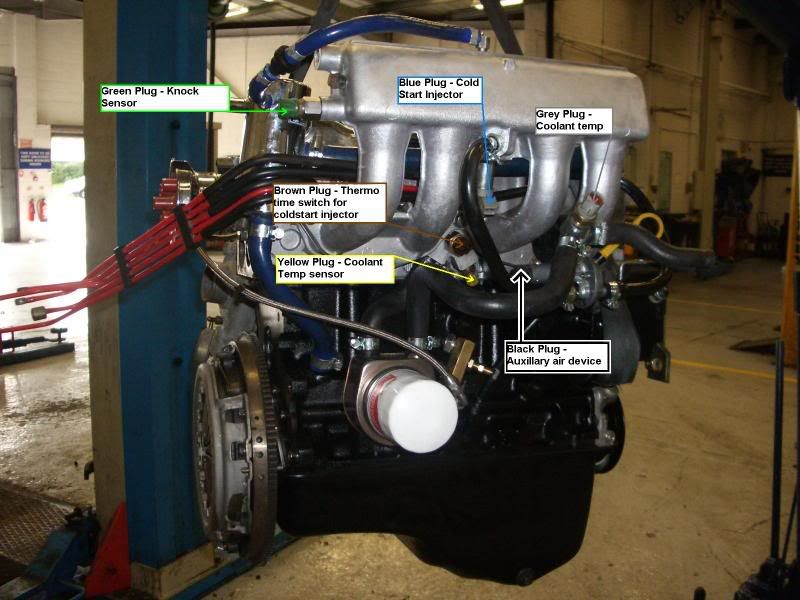
got a feeling some of my sensors are not plugged into the right hole firstly have i got these lead clours right....
black - throttle postion
black - air bypass valve
biege aux air ( under the cold start)
green - knock sensor
blue - cold start
yellow - thermo time switch ECT ??
dark yellow temp sensor
Now im trying to located all of these sensors i know where the cold start is and thats about it can anyone provide a diagram or a pic for me
cheers

Norris Motorsport
Joined: May 2003
Posts: 3,437
Likes: 3
From: Derbyshire
Yellow(S2) or white(S1) is ECT underneath inlet manifold, brown is thermo-time switch, green is knock sensor (later S2 only), blue is cold start fuel injector, black two pin is idle speed valve, black 3 pin is TPS, Air charge sensor is obvious!
Hope that clears that one up!
Hope that clears that one up!
Last edited by Karl; Jun 30, 2011 at 10:43 PM.
can anyone tell me what colour wires go to what colour plugs please?
Most of my plugs have been replaced with black ones, so I havent a clue what goes where

Thread
Thread Starter
Forum
Replies
Last Post
JK12
Pictures, video & Photoshop Forum
33
Apr 26, 2021 12:09 PM
STeve
Official Passionford Show Attendances
23
Sep 12, 2015 12:56 PM