
DIY head build and porting pictures inside **UPDATE** finally started

Thread Starter
PassionFord Post Whore!!
iTrader: (4)
Joined: Aug 2009
Posts: 4,790
Likes: 43
From: London
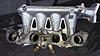
Cheers mate, yea i know would have loved to have it flow tested but just couldn't find any one close plus im running out of time a bit. From all the research i did peak flow figures aren't really the be all and end all of a decent head. Haven't really changed anything too drastic inlet side, just slightly larger and smoother lol
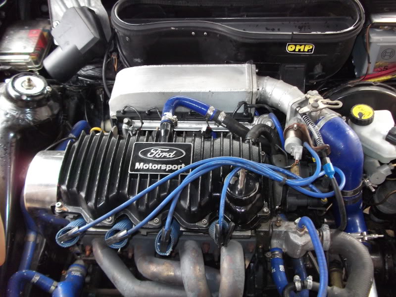
My initial engine spec wont have changed very much. Same cam, turbo etc so i will do a dyno run and compare, if i make the same or more power at the same boost with the lower CR the head has been an improvement
Rob,
My initial engine spec wont have changed very much. Same cam, turbo etc so i will do a dyno run and compare, if i make the same or more power at the same boost with the lower CR the head has been an improvement
Rob,
You must be itching to get it up and running now, I hate waiting on a build or a new mod!
I fitted my new Tacho and Speedo the other day and now REALLY cant wait for my Fuel and Water Temp gauges from Santa lol
lol
I fitted my new Tacho and Speedo the other day and now REALLY cant wait for my Fuel and Water Temp gauges from Santa
Yeah if only!! I get so impatient if I had the spare cash I'd buy them myself and then ask for something else for chirstmas  lol
lol
Mines never been off the road for a year, I think 6 months max and that was a fucking nightmare! Driving around in a 1.1 AX Forte!
lolMines never been off the road for a year, I think 6 months max and that was a fucking nightmare! Driving around in a 1.1 AX Forte!
Too many posts.. I need a life!!


Joined: Feb 2006
Posts: 795
Likes: 26
From: Canada
Good job Rob,
Smoothing out the sharp edges certainly will make a good bit of difference on both
inlet and exhaus side.
I agree peak flow figures are not all that usefull. However, the cvh head is difficult to get over the 165 cfm(28" depression and .450" lift) mark - even with large ground out ports. There are certain areas just below the valve that need reshaping.
One cannot discover this without the aid of a flowbench - or many years of blind trial and error building race engines. Instead of a flowbench to test the results of port reshaping one had to rely on dyno power or racetrack performance. For me I do not have years of building championship CVH engines to know where (other than initial common sense) to remove material (and where not to) so I choose the flowbench as a tool to do this.
Also careful examination of cross sectional flow velocities in the port and also exiting around the valve.
Cheers
Perry
Thread Starter
PassionFord Post Whore!!
iTrader: (4)
Joined: Aug 2009
Posts: 4,790
Likes: 43
From: London
Cheers mate,
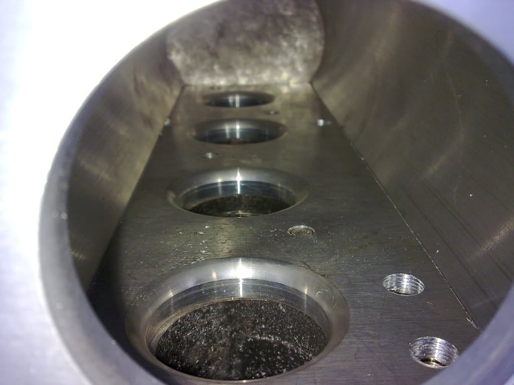
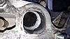
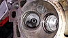
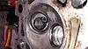
I was pretty careful around the back of the valve, and i'm hoping the 3 angle seats with cut back inlet valves should help at low lift. My aim was to use the standard valves, and keep the port area down. Im hoping to have a good torquey lowish lag motor, not aiming for a peaky 300brake, more a nice drivable 250 brake with similar torque figures.
What sort of features did you change around the back of the valve?
Thanks again,
Rob,
Too many posts.. I need a life!!
Joined: Feb 2006
Posts: 795
Likes: 26
From: Canada
Hello Rob,
Your head pics look good so far
I left my exhaust port exit size much smaller to keep up exhaust velocity.
We tested a port making it larger (almost the same size as ERST turbo manifold)
and did not see any flow increase. This means a definite velocity decrease.
Removing the intake valve guide in the inlet port is also a good thing. We saw a 10 to 12 cfm gain by removing the protruding guide. The air velocity near that valve guide is
extremely high. A 10 cfm increase in flow (if velocities are still in a good range) will yield
20 HP at 15 psi boost.
One note of caution - the inlet manifold.
The inlet manifold is a source of major airflow restriction as well.
Porting the cylinder head by itself, and not looking at the intake manifold
is a huge mistake.
We have ported a cvh head with standard 42mm valve to reach 193 cfm @28" and 0.450" valve lift. This was with a 36mm diameter inlet port (near factory size).
However, when we added the intake manifold nearly all of our 40+ cfm gain was gone.
After reshaping the inlet manifold we are at 175 cfm - still alot to gain.
I can certainly see a large gain made from a propper tested intake manifold.
Again, we would not have discovered how bad a factory intake was without the aid of a flowbench. Anyone who says flowbenches are useless - is fos.
Increasing the efficiency of the entire inlet path is free HP. Increased power at lower boost levels.
Cheers,
Perry
Too many posts.. I need a life!!
Joined: Feb 2006
Posts: 795
Likes: 26
From: Canada
Hello Karlos,
Unless one actually tests the flow of an intake manifold on a cylinder head you don't really know.
The harder (more expensive) way is switching inlet manifolds and testing on a rolling road.
A factory unmodified inlet will not support the airflow requirements of a modified head.
The factory manifolds may be modified to produce good results.
However, nearly all of the big HP guys have custom inlet manifolds - or at least modified factory inlets.
The inlet is far more important that a tubular exhaust manifold - up to 300 HP.
Just my opinion

Thread Starter
PassionFord Post Whore!!
iTrader: (4)
Joined: Aug 2009
Posts: 4,790
Likes: 43
From: London
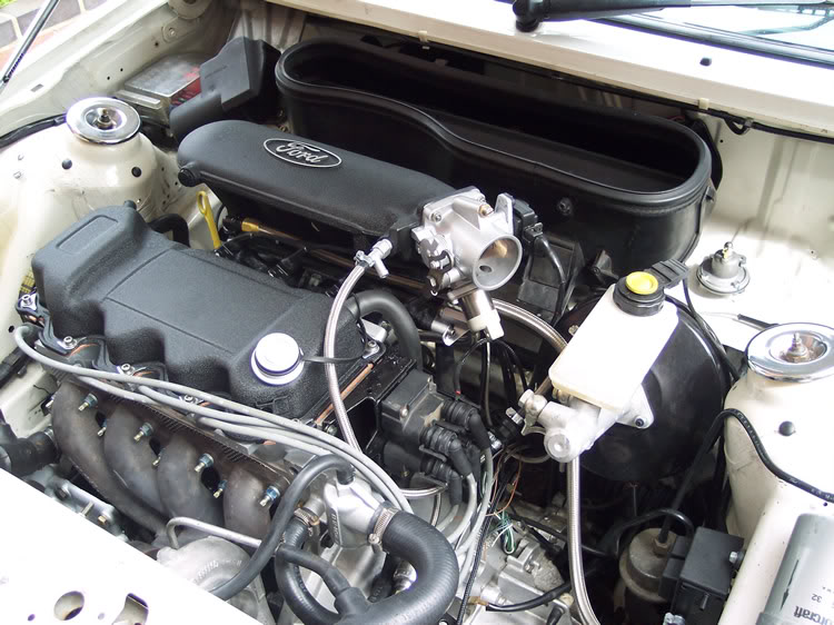
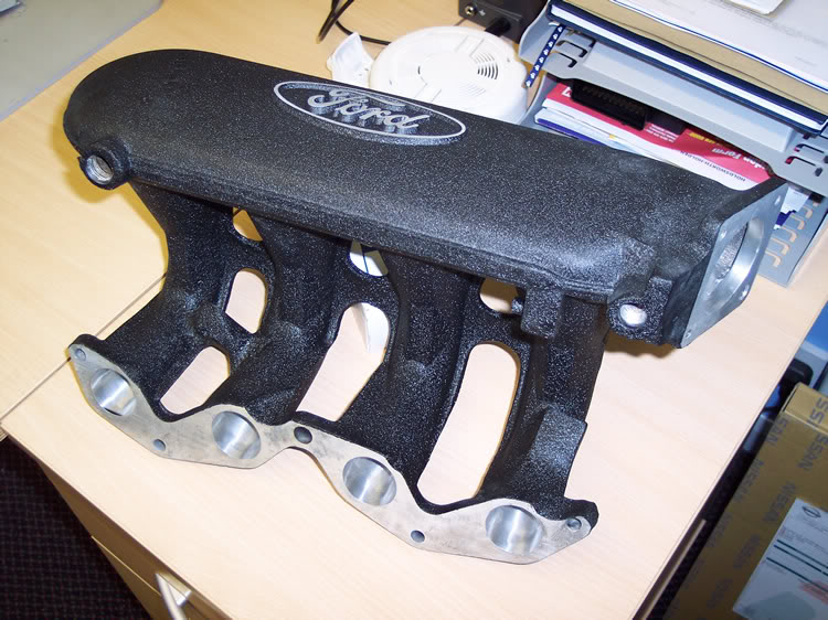
Cheers Perry, shame about the exhaust port  good thing to know for next time the inlets them selves are close to factory size, inlet manifold is next, made up a template to match the inlet to.
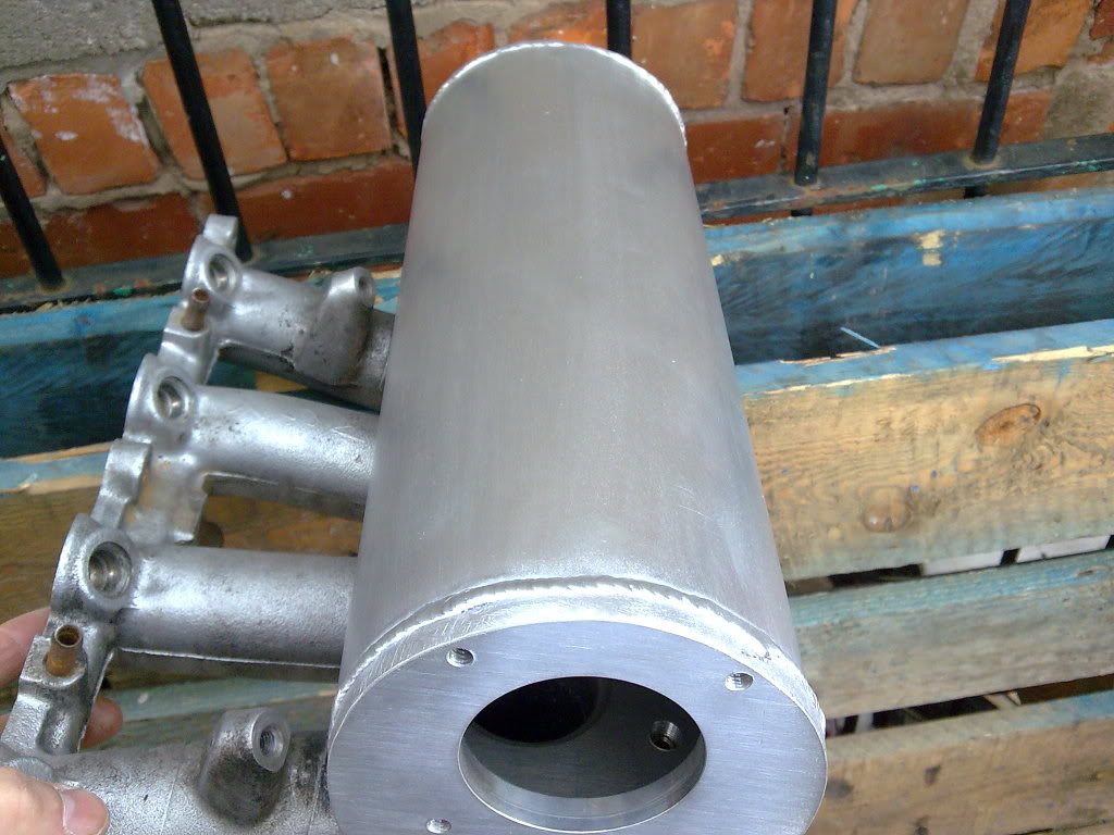
Have you flow tested a efi and mfi manifold back to back? im running my car in with the efi manifold but considering cutting open my mfi manifold to properly sort out the internal casting and having it re-tig welded.
Karlos - always loved the look of those manifolds when their done properly think one would really suit your car mate, im going to stick with the mfi manifold as i really want a stock looking bay.
Rob,

Too many posts.. I need a life!!
Joined: Feb 2006
Posts: 795
Likes: 26
From: Canada
Hello Karlos and all,
Custom intakes have the ability to flow better - usually just because the runner length is shorter and there is lower losses with a shorter port.
Once again beware - a homeade customized inlet manifold that has not been tested for equal flow in all 4 ports is taking a risk.
That is where flowbench development is critical.
You will find many builders saying flow benches are useless - they are full of rubbish.
How can you look at an inlet manifold and know that the flow distribution is equal?
The are some computational fluid dynamics software used for inlet development - these do work well , but the finished result is verified by - - - guess what? a flow bench.
Equal flow distribution means equal power for each cylinder and no lean cylinders to burn pistons. This is part of a good tune.
Flow bench testing here is not very expensive. Much less than the cost of inlet manifolds and head porting. One can have an inlet manifold and head tested for
$200.00 (all 4 ports) (less than 100 �)
All of this extra effort will lead to a relaible, much more powerful(at lower boost) engine.
Hope this helps.

Too many posts.. I need a life!!
Joined: Jul 2004
Posts: 992
Likes: 3
From: United Kingdom southend on sea
Looking good rob.some handy advice canada.i had my head done to stage 3 spec.the exhaust side ports were only made slightly bigger compared to other stage3 heads id seen.they used flow bench.bigger is not always better then.anyone know a place who could port my inlet mfi...

Advanced PassionFord User
Joined: Aug 2006
Posts: 1,553
Likes: 1
From: wirral
ooh and i thought you just wanted to mock someones down pipe up on it and instead you were taking sneaky pictures p.s those mtx mounts you do i think i might aswell get my name down now as i think the extra from the gas will see this box of


Virgin
Joined: Apr 2015
Posts: 1
Likes: 0
From: Hungary
Hello all,
I've found this topic very interesting and extremely useful! Thanks for all the information, based on these I've made myself a ported head for my mfi XR3i.
Using a Dremel tool, I made the inlets match with the head perfectly. At first, I was afraid that this will reduce swirling and by this, fuel atomisation. But then I've noticed that the port shape should be enough for good atomisation and mixture, because it generates a good swirl.
I did some machining behind the throttle body, too.

I'll make more pictures soon...
Anyway, here is my Escort:


Rob, have you finished the ported head? How is the RST going? I see this thread ended in 2010 without built in results,I hope everything is ok.
Cheers,
Balazs
I've found this topic very interesting and extremely useful! Thanks for all the information, based on these I've made myself a ported head for my mfi XR3i.
Using a Dremel tool, I made the inlets match with the head perfectly. At first, I was afraid that this will reduce swirling and by this, fuel atomisation. But then I've noticed that the port shape should be enough for good atomisation and mixture, because it generates a good swirl.


I did some machining behind the throttle body, too.

I'll make more pictures soon...
Anyway, here is my Escort:


Rob, have you finished the ported head? How is the RST going? I see this thread ended in 2010 without built in results,I hope everything is ok.
Cheers,
Balazs

Thread
Thread Starter
Forum
Replies
Last Post
steerfromdarear
Restorations, Rebuilds & Projects.
28
Jan 29, 2016 06:14 PM
CabrioTurbo
General Car Related Discussion.
1
Aug 1, 2015 11:04 AM