
DIY head build and porting pictures inside **UPDATE** finally started

Thread Starter
PassionFord Post Whore!!
iTrader: (4)
Joined: Aug 2009
Posts: 4,790
Likes: 43
From: London
Hi all,
In a few weeks i will be rebuilding my EFI head, so thought i would start a thread with a few do's and don't, bit of an info hub for head shizzle,
Any way my plan is to clean up the ports and carefully match the manifolds up, enlarge the ports slightly (not much) as i want to maintain gas velocity and keep standard valves etc. The valve seats are going to be 3 angle cut and the valves will be back cut, this really improves gas flow at low/mid valve lift (apparently). Then the valve guided (bronze) will be cut back to the port.
Any info or ideas would be really really helpful, im going to steal some photos from a few other threads which should give an idea on port shape etc.
Cheers
Rob,
Last edited by Rob_DOHC; Nov 13, 2010 at 10:00 PM.
Thread Starter
PassionFord Post Whore!!
iTrader: (4)
Joined: Aug 2009
Posts: 4,790
Likes: 43
From: London
Right,
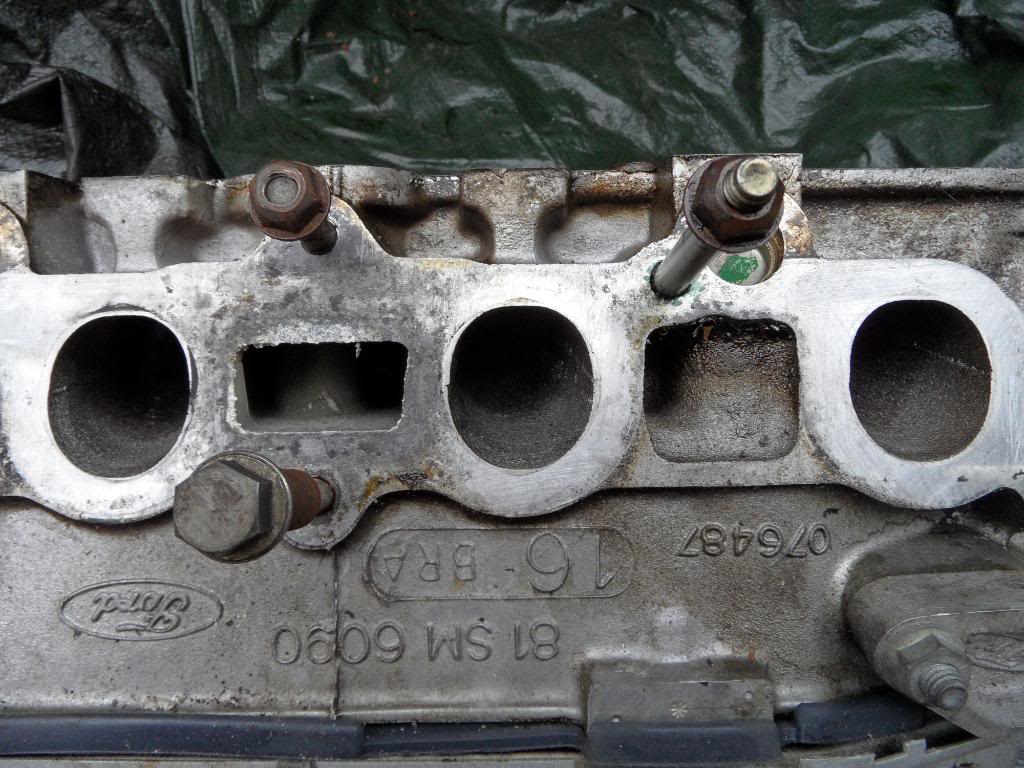
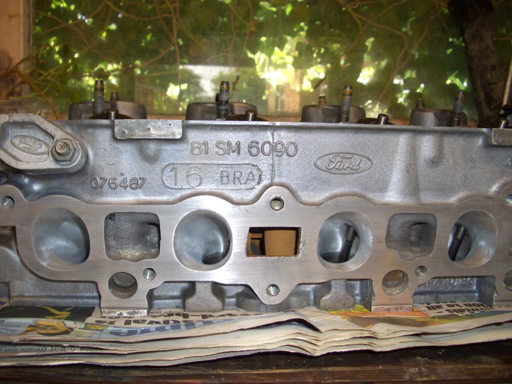
Thought i would have a look at the standard heads (mfi) match with a standard inlet manifold (mfi) and was shocked at how bad it was!
The next couple of photos show the difference in initial port shape between mfi and efi

The difference on the face is obvious, however what is less obvious is the subtle port shape difference behind the valve, the mfi head is fairly smooth etc, the efi head has quite a sharp angular lip on the inside edge of the port behind the valve, i think this is to promote swirl etc, but will get some good shots when the valves are removed.
Another observation, the bare castings are fairly different too, the mfi head seems to have been of higher quality, with less flashing and defects, other than the ports they seem identical, the efi inlet ports are also 1mm larger across....
Rob,
Thought i would have a look at the standard heads (mfi) match with a standard inlet manifold (mfi) and was shocked at how bad it was!
The next couple of photos show the difference in initial port shape between mfi and efi
The difference on the face is obvious, however what is less obvious is the subtle port shape difference behind the valve, the mfi head is fairly smooth etc, the efi head has quite a sharp angular lip on the inside edge of the port behind the valve, i think this is to promote swirl etc, but will get some good shots when the valves are removed.
Another observation, the bare castings are fairly different too, the mfi head seems to have been of higher quality, with less flashing and defects, other than the ports they seem identical, the efi inlet ports are also 1mm larger across....
Rob,
Last edited by Rob_DOHC; May 9, 2010 at 08:25 PM.
Thread Starter
PassionFord Post Whore!!
iTrader: (4)
Joined: Aug 2009
Posts: 4,790
Likes: 43
From: London
Yep, they will be refacing it, installing bronze guides, machining the valves and cutting the 3 angle seats, should be interesting. I know they are really mismatched! Hows the beast mate?
Any one know who can flow test heads? would be quite nice to get a comparison before and after porting if its not too expensive.
Rob,
Any one know who can flow test heads? would be quite nice to get a comparison before and after porting if its not too expensive.
Rob,
Thread Starter
PassionFord Post Whore!!
iTrader: (4)
Joined: Aug 2009
Posts: 4,790
Likes: 43
From: London
I know lol, going to take a few more comparison shots with the valves out, also Karlos do you mind if i re post some of the photos you posted of your head? the more heads i can compare from different well known companies the more i will learn what not to do etc.
Rob,
Rob,

Trending Topics
Thread Starter
PassionFord Post Whore!!
iTrader: (4)
Joined: Aug 2009
Posts: 4,790
Likes: 43
From: London
Cheers buddy, when i find them i will 
The guides are roughly �50 from burtons, they should probably cost �20 to remove old ones and fit the new,
The 3 angle seats is �12 a valve (i think), probably a bit pointless to just do that.
Might try and remove the guides my self as i want to do the port work and then take it in to be acid dipped and machined.
Rob,
how much dose it cost to get 3 angle seats cut and bronze quides fited am thinkin of getin my s2 head dne depending on price
The 3 angle seats is �12 a valve (i think), probably a bit pointless to just do that.
Might try and remove the guides my self as i want to do the port work and then take it in to be acid dipped and machined.
Rob,
Rob not tryin to be funny but is t worth doing yourself?
If the guides are 50 + 20 for fitting
Valve seats are 12 each that's 94
so that's 166 before anything else I've seen stage 3 heads go for 200 with big valves etc
I understand the apeal of doing it yourself just is it worth it
If the guides are 50 + 20 for fitting
Valve seats are 12 each that's 94
so that's 166 before anything else I've seen stage 3 heads go for 200 with big valves etc
I understand the apeal of doing it yourself just is it worth it
Thread Starter
PassionFord Post Whore!!
iTrader: (4)
Joined: Aug 2009
Posts: 4,790
Likes: 43
From: London
A fair point there mate, i will be doing it for 2 reasons,
1) i want to learn
2) essentially ALL of the 'stage 3' heads you see for sale on ebay will be shocking, even some heads i have seen pictures of from so called 'decent' companies are crap, i will post up some pictures of Karlos's head which is brilliant (although not what i will be doing as such) then compare this to some of the 'stage 3' heads you see on ebay, the difference is MASSIVE but thats why his head was a grand not �200.....
Unless it has been ported by a well known company OR by some one i trust who is intelligent enough to know the rights and wrongs then �200 is an expensive fail.
Trouble is, its very easy to make a head worse than stock, im going for a good flow improvement and a head that compliments my engine which is a 6000rpm lump with stacks of low-mid range torque, not out right power.
Rob,
Last edited by Rob_DOHC; Oct 21, 2012 at 12:41 PM. Reason: spelling
Thread Starter
PassionFord Post Whore!!
iTrader: (4)
Joined: Aug 2009
Posts: 4,790
Likes: 43
From: London
This for example
On the face of it it looks quite smart, but the guides have not been cut back, and although the finish on the ports is alright i think material had just been removed, this is not the aim of the game, you want to decrease restriction to flow WITHOUT damaging the heads ability to create mixture swirl or loose gas velocity, By just straightening a CVH inlet port you create quite a large void behind the valve, if you go from a small diameter tube to a large one (which essentially you would do) the gas velocity decreases and the mixture 'stalls' behind the valve not good, if any thing you want the mixture to increase in speed behind the valve.
This is basically what i have read and learnt from talking to pretty knowledgeable people, but i haven't done it and would really appreciate some advice from the guys who have.
Rob,
Thread Starter
PassionFord Post Whore!!
iTrader: (4)
Joined: Aug 2009
Posts: 4,790
Likes: 43
From: London
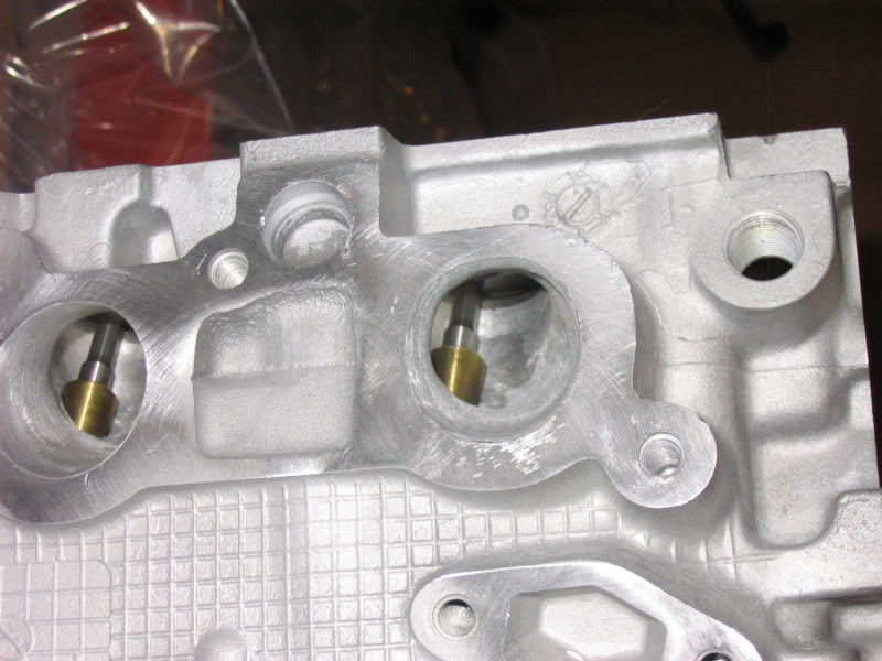
Comparison of inlet ports, i am stealing some photos here so if any one wants them removed just PM me.
Standard MFI
Standard EFI

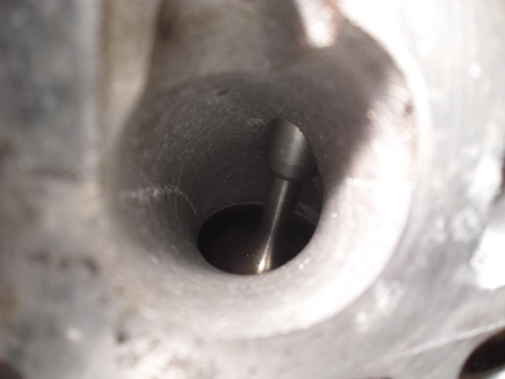
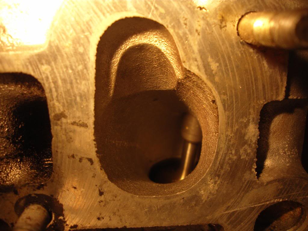
Karlos NMS beauty
Project rs's NMS head
And finally Juffers Power engineering head
If any one has any more photos for comparison that would be really handy! I suspect that NMS have done more flow bench testing than Power engineering, there are some clear differences between the two as well, interesting that NMS made a clear effort to keep the port shape (the bend) behind the valve, albeit probably bigger, but not hugely larger than standard i don't think in that area, the rest of the port is much larger than stock,
Rob,
Standard MFI
Standard EFI
Karlos NMS beauty
Project rs's NMS head
And finally Juffers Power engineering head
If any one has any more photos for comparison that would be really handy! I suspect that NMS have done more flow bench testing than Power engineering, there are some clear differences between the two as well, interesting that NMS made a clear effort to keep the port shape (the bend) behind the valve, albeit probably bigger, but not hugely larger than standard i don't think in that area, the rest of the port is much larger than stock,
Rob,
Last edited by Rob_DOHC; May 10, 2010 at 01:49 PM.
one thing to bare in mind rob is NOT to Polish the inlets leave them as rough as you can it helps eliminate flat spots
if doing exhaust ports aswell then they need to be polished as this helps with flow of exhaust gasses
and i've seen companies polish both and end up makeing flow worst than stock as you said
if doing exhaust ports aswell then they need to be polished as this helps with flow of exhaust gasses
and i've seen companies polish both and end up makeing flow worst than stock as you said
Thread Starter
PassionFord Post Whore!!
iTrader: (4)
Joined: Aug 2009
Posts: 4,790
Likes: 43
From: London
Haha thanks very much mate! the reason you shouldn't mirror the inlets is because the fuel mixture sticks to the port walls more ie not atomised, and your right this is one reason why badly thought out heads make less power, the exhaust ports and combustion chamber can be mirror polished apparently to reduce carbon build up, in practice it just makes the head look pretty.
Rob,
Rob,
well don't know about help prevent carbon build up but suppose that is true as it does flow exhaust gasses out quicker so would cuase less build it
one of the many factures i learnt at college lol
ill be doing my own head too
but actually think its been ported already so going to check when i remove my current head off and compare them then
one of the many factures i learnt at college lol
ill be doing my own head too
but actually think its been ported already so going to check when i remove my current head off and compare them then
Thread Starter
PassionFord Post Whore!!
iTrader: (4)
Joined: Aug 2009
Posts: 4,790
Likes: 43
From: London
Right found a few minutes
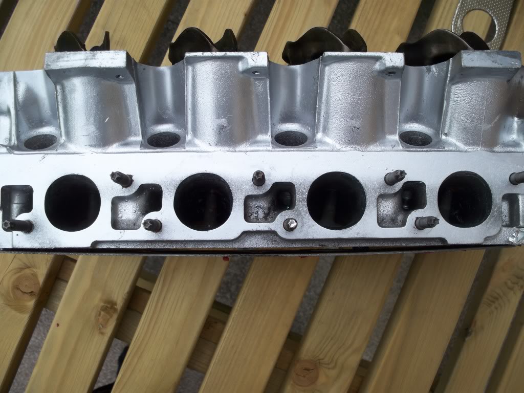
Exhaust ports
Standard
Karlos's exhaust ports (NMS) larger valves if i remember correctly
Project rs's NMS head
and a bloody useful shot!
One from Juffer a power engineering head
All for now, just need some ideas now! think i will get a pneumatic pencil grinder for doing this stuff, or buy a decent dremel
Rob,
Thread Starter
PassionFord Post Whore!!
iTrader: (4)
Joined: Aug 2009
Posts: 4,790
Likes: 43
From: London
Interesting how different the two NMS exhaust ports are, project rs (if you happen to read this) were the valves in your head standard size? Also the powers exhaust port seems to have had loads more material removed than both NMS heads.
Any one got any flow figures?
Rob,
Any one got any flow figures?
Rob,
Too many posts.. I need a life!!
Joined: Apr 2007
Posts: 934
Likes: 0
From: worcester
Don't know if this helps you in any way but my power engineering head has large valves. Looking at it in the photos there is more material that has been taken away compared to the NMS heads. Maybe having the bigger valves is something to do with the larger port size for a faster flowing volume of air? I could be barking up the wrong tree of course lol
Bigger valves and ports will actually slow the air speed at low rpm/boost, but allows for a greater flow at high rpm/boost.
Some Jap motors (200sx S13 for example) have only half the inlet ports open at low rpm/boost and then open them up fully at higher rpm/boost, this maintains good response low down but still allowing good flow up top.
Some Jap motors (200sx S13 for example) have only half the inlet ports open at low rpm/boost and then open them up fully at higher rpm/boost, this maintains good response low down but still allowing good flow up top.
Last edited by Karlos G; May 10, 2010 at 09:59 PM.


and also one other thing is putting bigger exhuasts valves in makes absolutly no difference at all so a 37mm exhuast valve is ample which is standard size
its the inlets that make the difference think the biggest you can go inlet wise is 43mm unless you have the rare cross hatch heads and then you can get 45mm ones in as walls are thicker still
hope this helps
its the inlets that make the difference think the biggest you can go inlet wise is 43mm unless you have the rare cross hatch heads and then you can get 45mm ones in as walls are thicker still
hope this helps
PassionFord Post Whore!!

Joined: Jan 2007
Posts: 4,995
Likes: 14
From: merseyside
Interesting how different the two NMS exhaust ports are, project rs (if you happen to read this) were the valves in your head standard size? Also the powers exhaust port seems to have had loads more material removed than both NMS heads.
Any one got any flow figures?
Rob,
Any one got any flow figures?
Rob,

Thread Starter
PassionFord Post Whore!!
iTrader: (4)
Joined: Aug 2009
Posts: 4,790
Likes: 43
From: London
Ahh cheers crazycage, sorry mate is it Dave? just feels strange typing crazycage all the time!
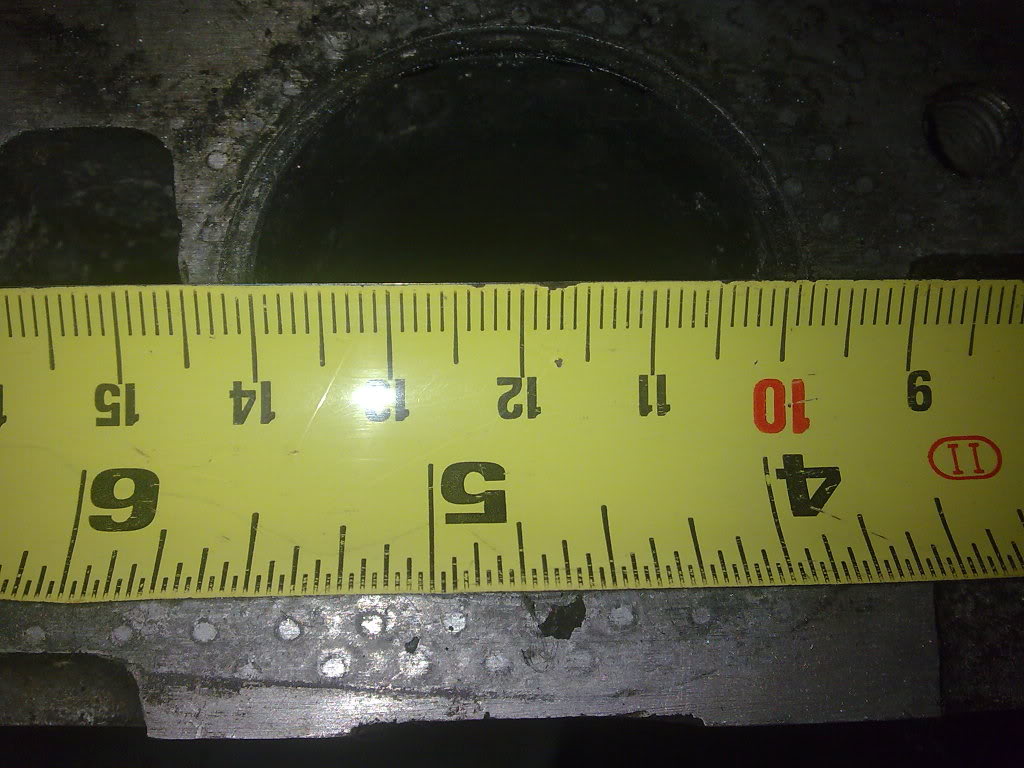
And Muz that would be superb fella, if you could put a ruller across the ports that would be brilliant!
Thanks very much!
Rob,
And Muz that would be superb fella, if you could put a ruller across the ports that would be brilliant!
Thanks very much!
Rob,
Last edited by Rob_DOHC; May 11, 2010 at 09:33 AM.
Thread Starter
PassionFord Post Whore!!
iTrader: (4)
Joined: Aug 2009
Posts: 4,790
Likes: 43
From: London
Don't know if this helps you in any way but my power engineering head has large valves. Looking at it in the photos there is more material that has been taken away compared to the NMS heads. Maybe having the bigger valves is something to do with the larger port size for a faster flowing volume of air? I could be barking up the wrong tree of course lol
Bigger valves and ports will actually slow the air speed at low rpm/boost, but allows for a greater flow at high rpm/boost.
Some Jap motors (200sx S13 for example) have only half the inlet ports open at low rpm/boost and then open them up fully at higher rpm/boost, this maintains good response low down but still allowing good flow up top.
Some Jap motors (200sx S13 for example) have only half the inlet ports open at low rpm/boost and then open them up fully at higher rpm/boost, this maintains good response low down but still allowing good flow up top.
I'll post up my book marks later for the head porting. Some interesting articles in there
Rob
Too many posts.. I need a life!!

Joined: Feb 2006
Posts: 795
Likes: 26
From: Canada
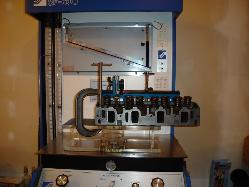
I have seen very few actual flowbench test results with CVH heads. I do know that Cnc Heads certainly does use a flow bench to develop their port profiles - which are then digitized for use with the 5 axis cnc machine. Complete flow test resuts are very important.
Flow bench test figures by themselves do not guarantee performance increases.
However, one can map port velocities, as well as port swirl ( flow bench attachment ).
For low rpm use (and emissions and economy) maintaining high swirl is a benefit.
For high rpm (performance) use the opposite is true - swirl does not aid power production,
in fact the fuel starts to separate from the air-fuel mix resulting in much lower power output and high BSFC.
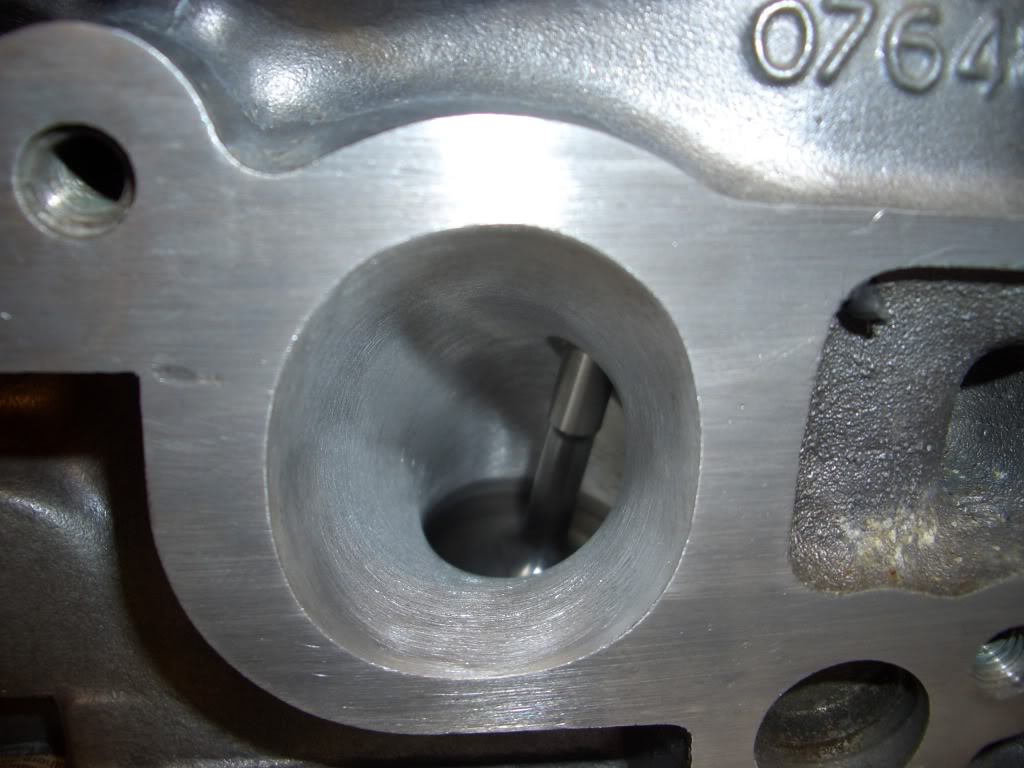
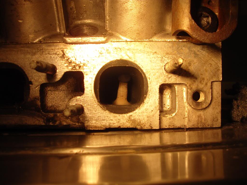
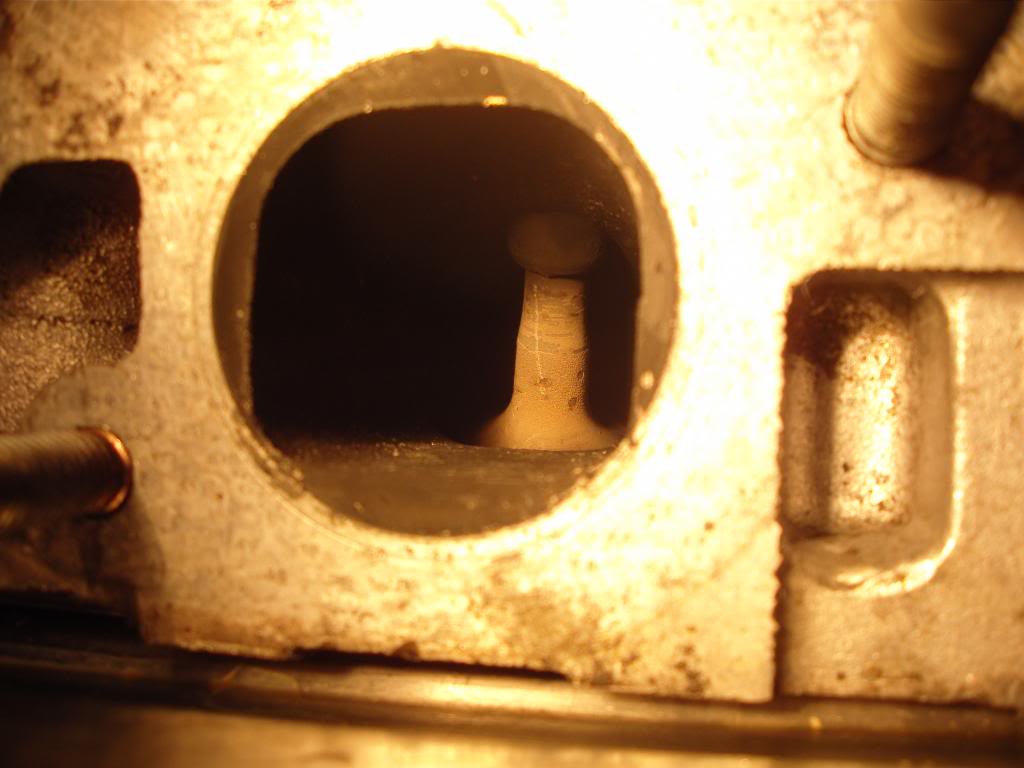
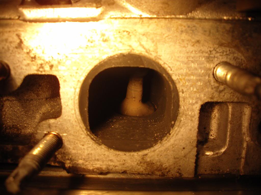
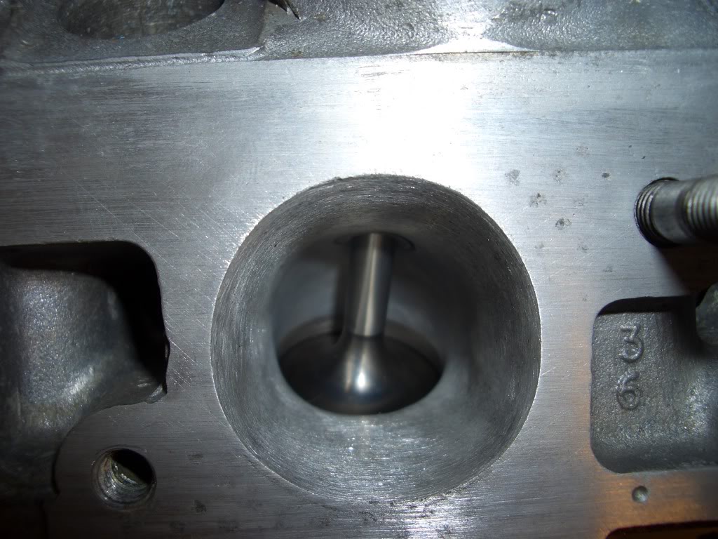
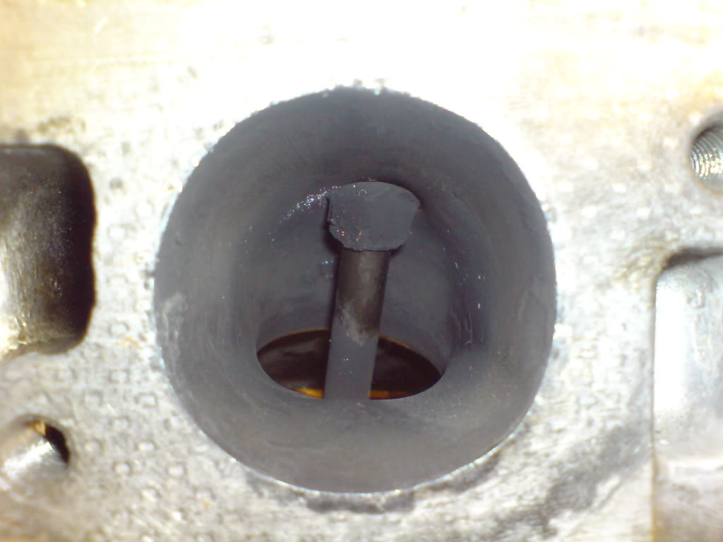
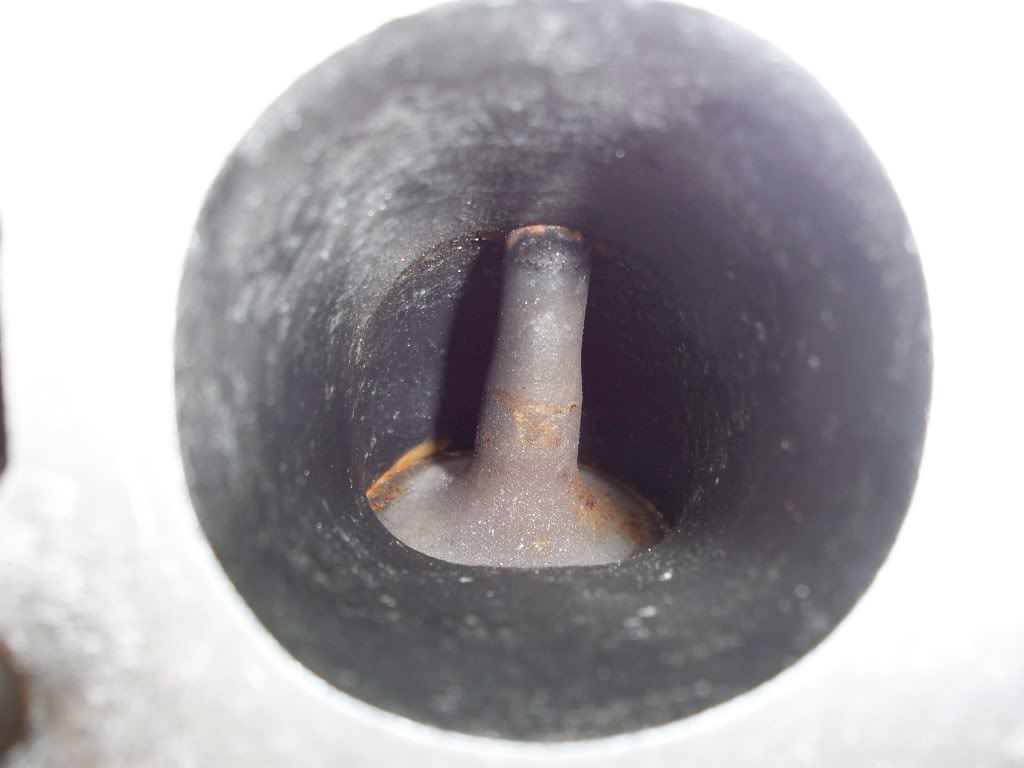
We have been developing a CVH head here in Canada. There are a few areas that are very responsive to major flow increases without much material removal. This cannot be done without the aid of a flow bench. The port has a high velocity areas, and low velocity areas.
It is quite a complex port to get right.
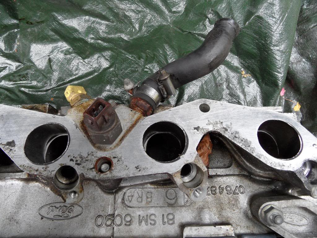
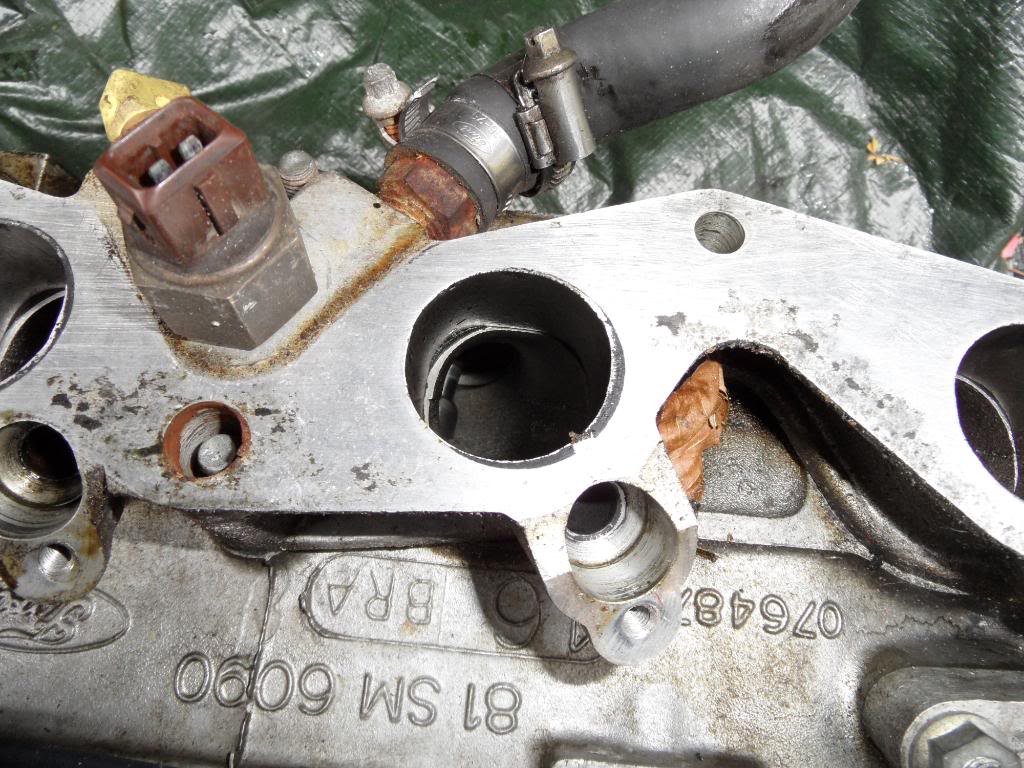
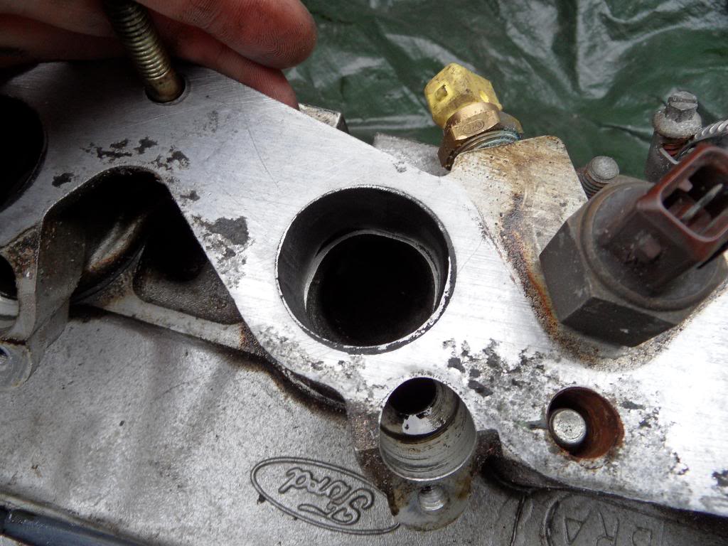
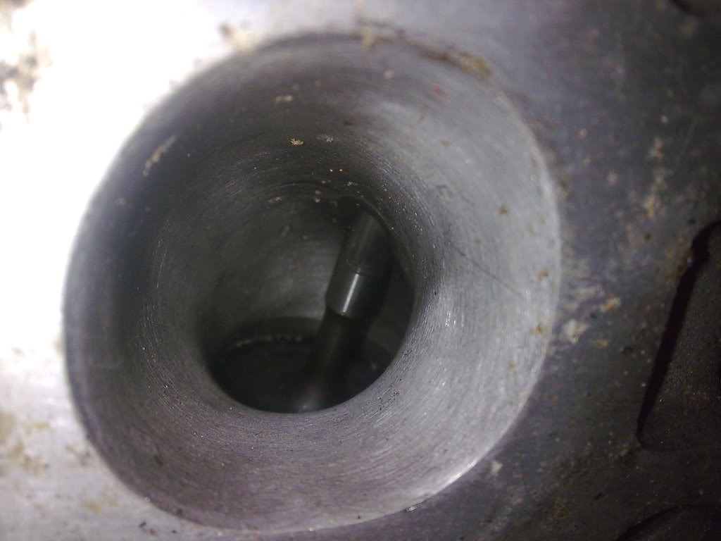
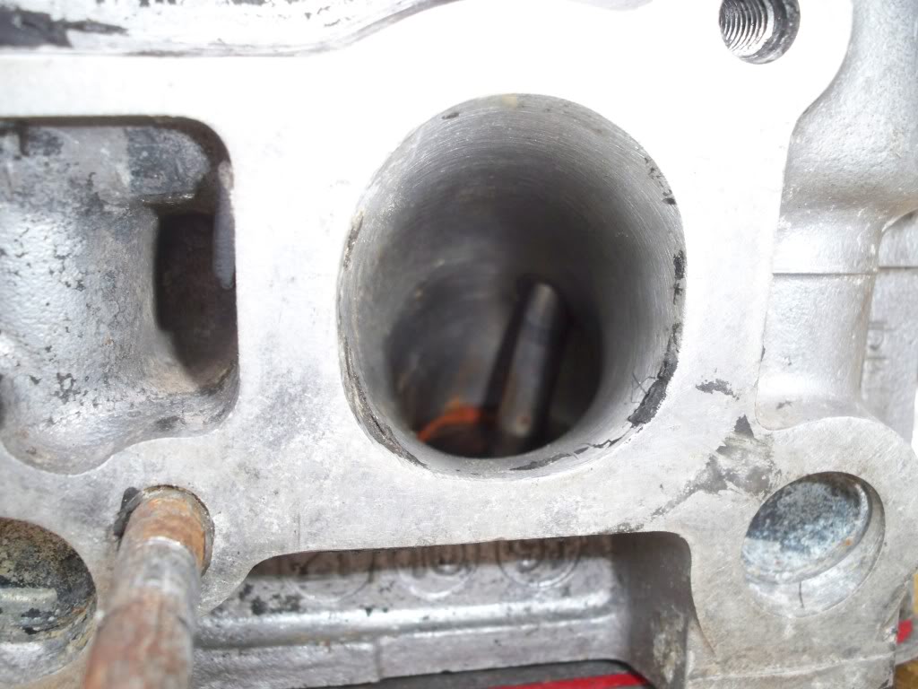
I have attached a pic of the head we started with. The protruding valve guide was made flush with the port since the picture was taken.
The inlet manifold must also be worked on. No point working on the head by itself - the inlet manifold is part of the inlet - major power improvements can be made here.
Love to see others results.
Flow bench test figures by themselves do not guarantee performance increases.
However, one can map port velocities, as well as port swirl ( flow bench attachment ).
For low rpm use (and emissions and economy) maintaining high swirl is a benefit.
For high rpm (performance) use the opposite is true - swirl does not aid power production,
in fact the fuel starts to separate from the air-fuel mix resulting in much lower power output and high BSFC.
We have been developing a CVH head here in Canada. There are a few areas that are very responsive to major flow increases without much material removal. This cannot be done without the aid of a flow bench. The port has a high velocity areas, and low velocity areas.
It is quite a complex port to get right.
I have attached a pic of the head we started with. The protruding valve guide was made flush with the port since the picture was taken.
The inlet manifold must also be worked on. No point working on the head by itself - the inlet manifold is part of the inlet
Love to see others results.
PassionFord Post Whore!!
Joined: Jan 2007
Posts: 4,995
Likes: 14
From: merseyside
I've found that life I needed.. It's HERE!!
Joined: Dec 2006
Posts: 1,374
Likes: 0
From: oxford
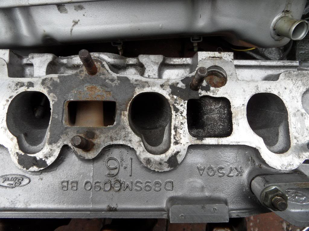
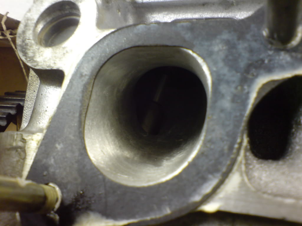
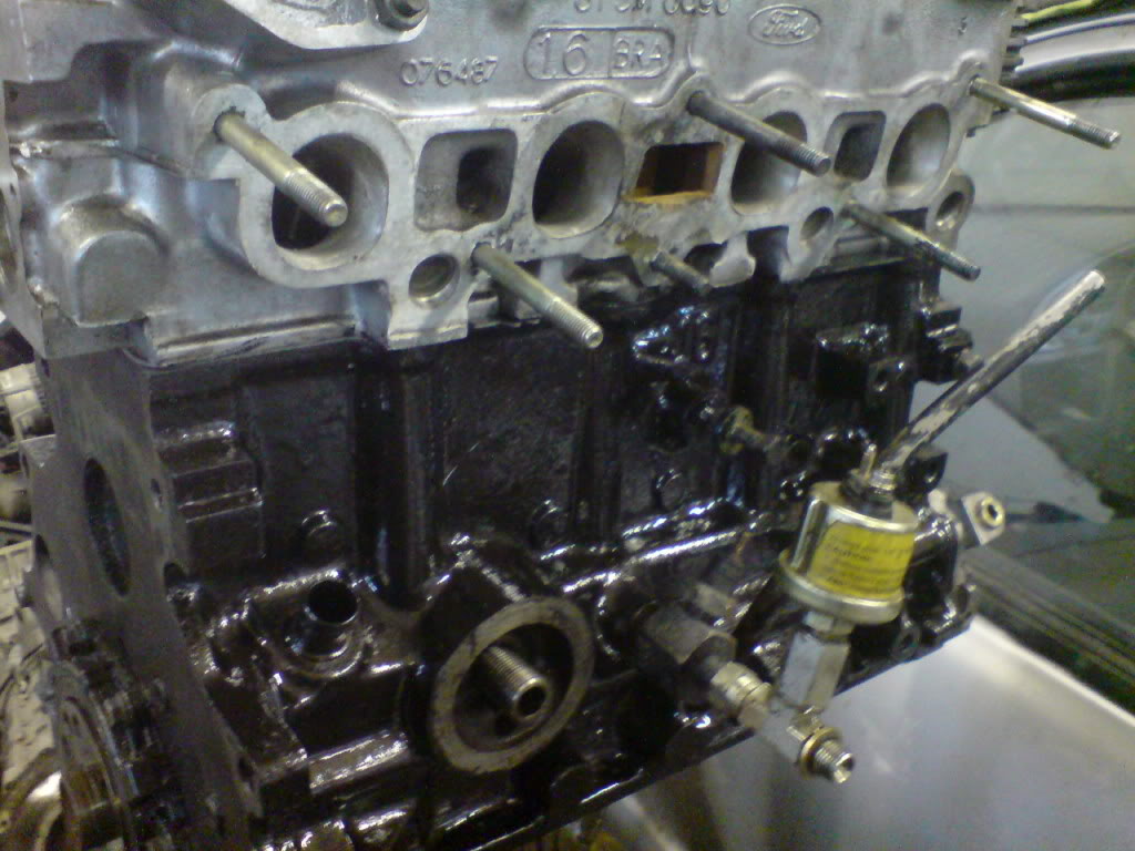
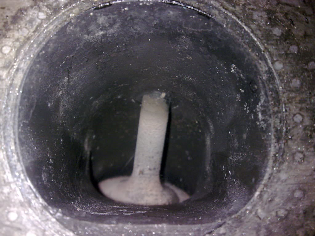
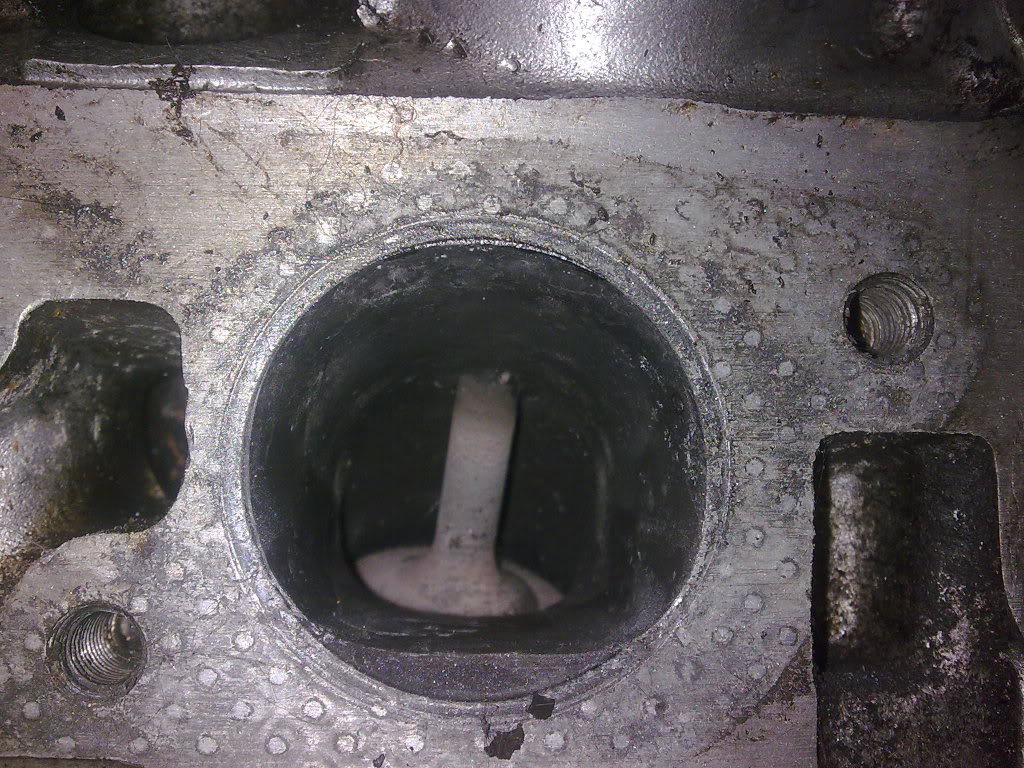
After reading this thread I thought I'd post up some pics of my head which I have aquired to see what you all think. It is dirty in the pics but im looking for input on port size/shape and how good of a job you think it is?
Exhaust:
Close-up:
Inlet:
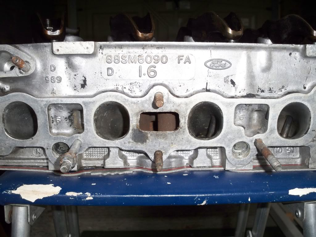
Close-up:
Let me know what you think???
Exhaust:
Close-up:
Inlet:
Close-up:
Let me know what you think???
Too many posts.. I need a life!!
Joined: Feb 2006
Posts: 795
Likes: 26
From: Canada
It is impossible to look at a picture of a cylinder head port and know if it "works" or doesn't.
A port can be carefully ground and finished so it looks great - and that is it. It could be worse than factory - you don't know.
The engine dyno or racetrack (best dyno on earth) will tell you if the engine (head, inlet, camshaft, turbo etc.....) was a well designed combination. A good flowing inlet and head will also produce higher power at lower boost levels.
Cheers
Thread Starter
PassionFord Post Whore!!
iTrader: (4)
Joined: Aug 2009
Posts: 4,790
Likes: 43
From: London
Cool, cheers for setting me straight Gary, no idea where i got Dave from???
and Canada 1 cheers for the info i was infact reading a few of your old posts the other day!, i have a few pictures of theoretically perfect single ports some where i will dig out, the drawings infact had deliberate areas promoting high and low velocity, and a 'bottle neck' well placed and sized seemed to work incredibly well promoting the venturi effect..... however how relevant that is on a forced induction port i don't know.
I can see what you mean, but this thread is really about the comparison of modified heads with stock..... it would be really helpful to have flow figures etc but for the time being i will be basing good and bad on the NMS head (the bench mark), which would have been flow tested to death im sure, we can easily see from pictures which parts of the ports have been altered/enlarged/reshaped and so can probably base what is good and bad on whether its similar to the NMS head......
Have you got any more pictures of your head canada1? would be great to see, and also have you got any flow bench figures, especially flow bench figures which correspond to a change you have made like stock vs cut back valve guides etc.
Thanks very much!
Rob,
and Canada 1 cheers for the info i was infact reading a few of your old posts the other day!, i have a few pictures of theoretically perfect single ports some where i will dig out, the drawings infact had deliberate areas promoting high and low velocity, and a 'bottle neck' well placed and sized seemed to work incredibly well promoting the venturi effect..... however how relevant that is on a forced induction port i don't know.
It is impossible to look at a picture of a cylinder head port and know if it "works" or doesn't.
A port can be carefully ground and finished so it looks great - and that is it. It could be worse than factory - you don't know.
A port can be carefully ground and finished so it looks great - and that is it. It could be worse than factory - you don't know.
Have you got any more pictures of your head canada1? would be great to see, and also have you got any flow bench figures, especially flow bench figures which correspond to a change you have made like stock vs cut back valve guides etc.
Thanks very much!
Rob,
Too many posts.. I need a life!!
Joined: Feb 2006
Posts: 795
Likes: 26
From: Canada
Greetings Rob,
When you make a port mold you can see and measure the port taper, and measure accurately the port cross sectional areas. Port CSA is important for airspeed velocity.
Reshaping critical areas is the difference between a winner and a loser. Dave Baker is a great old school Ford guy that has done plenty of CVH heads in his day. He certainly knows where and how much to remove to shape the port correctly.
Different applications have different port requirements. A 5000 rpm 1.6 cvh doesn't need
much more than a good valve job. The CVH head flow in standard form is fine for a low rpm
application. High boost and high rpm is a new story.
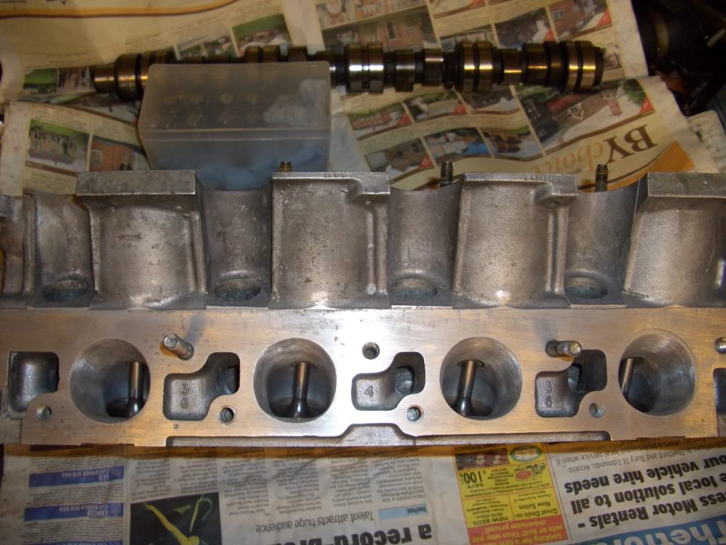
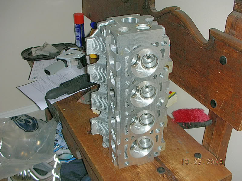
I purchased a virgin CVH head to work on. Wanted no cracks and the thickest deck possible. Found a never used (in the Ford box) head. It is machined for roller lifters.
A forum like this one is great for sharing experience and expertise. Hope more chime in with their knowledge and information.
Cheers
Flow bench for development
When you make a port mold you can see and measure the port taper, and measure accurately the port cross sectional areas. Port CSA is important for airspeed velocity.
Reshaping critical areas is the difference between a winner and a loser. Dave Baker is a great old school Ford guy that has done plenty of CVH heads in his day. He certainly knows where and how much to remove to shape the port correctly.
Different applications have different port requirements. A 5000 rpm 1.6 cvh doesn't need
much more than a good valve job. The CVH head flow in standard form is fine for a low rpm
application. High boost and high rpm is a new story.
I purchased a virgin CVH head to work on. Wanted no cracks and the thickest deck possible. Found a never used (in the Ford box) head. It is machined for roller lifters.
A forum like this one is great for sharing experience and expertise. Hope more chime in with their knowledge and information.
Cheers
Flow bench for development

Advanced PassionFord User
Joined: Aug 2006
Posts: 1,553
Likes: 1
From: wirral
i also have a ported efi head and that was pretty much identical to the nms head (done by jamsport) but with standard valves but got no pictures of that one as it's on the car at moment but will see what i can do
Thread Starter
PassionFord Post Whore!!
iTrader: (4)
Joined: Aug 2009
Posts: 4,790
Likes: 43
From: London
Brilliant cheers Canada1! Can't believe you found a new head! Machined for roller lifters? Did ford ever fit roller lifters to stock cars? Any way im sure i will be asking you lots of questions in the near future!
Project, i was hoping you would chip in, you've helped in the past with my head questions,,,,, your heads on the car at the moment...... so if you hurry up and blow it up we can all have a good look at it?
Rob,
Project, i was hoping you would chip in, you've helped in the past with my head questions,,,,, your heads on the car at the moment...... so if you hurry up and blow it up we can all have a good look at it?
Rob,