
Engine maps....VE changes and Fuel pressure???


Thread Starter
PassionFord Post Troll

Joined: Jul 2003
Posts: 2,582
Likes: 0
From: Suffolk
If i were to improve airflow through my plenum, this would cause the VE to change.
The change should effect the entire map making it leaner throughout due to any increase in airflow, but what im wondering is can this be corrected by increasing the fuel pressure???
i.e. With the car running as it should (runs sweet ), fit modifed inlet then road test car, take lambda readings, adjust fuel pressure up and retest until lambda is restored to original setting......
Would this work???
The change should effect the entire map making it leaner throughout due to any increase in airflow, but what im wondering is can this be corrected by increasing the fuel pressure???
i.e. With the car running as it should (runs sweet
Would this work???


Part of the Furniture
Joined: Jun 2005
Posts: 156
Likes: 1
From: Australia
Originally Posted by CosRush
If i were to improve airflow through my plenum, this would cause the VE to change.
The change should effect the entire map making it leaner throughout due to any increase in airflow, but what im wondering is can this be corrected by increasing the fuel pressure???
i.e. With the car running as it should (runs sweet ), fit modifed inlet then road test car, take lambda readings, adjust fuel pressure up and retest until lambda is restored to original setting......
Would this work???
The change should effect the entire map making it leaner throughout due to any increase in airflow, but what im wondering is can this be corrected by increasing the fuel pressure???
i.e. With the car running as it should (runs sweet
Would this work???
If there was a gain you will find that the gain will be at boost/certain rpm�s only and not at light throttle/cruise. If you increase the fuel pressure to compensate you will find it �may� help at certain rpm's/load but not everywhere and may run rich at light throttle/cruise due to the increase in fuel pressure.
I'm talking from experience based on the re-tuning i did on my Autronic ecu once i fitted my Intake manifold to my cossie.
Good luck with it mate
Part of the Furniture
Joined: Jun 2005
Posts: 156
Likes: 1
From: Australia
Originally Posted by CosRush
Oh 
So there's no way of using a new plenum design without having to have a remap???
Thats bad news
Like you plenum by the way

Who made it???
So there's no way of using a new plenum design without having to have a remap???
Thats bad news
Like you plenum by the way
Who made it???
It really would come down to the design of the Intake manifold and how accurate you want the map to be. Its worth fitting your new plenum and trying it on a rolling road/chassis dyno cos if there is a major lean out then the dyno operator can back off the throttle.
The Inatke manifold was made by a friend of mine "Jim", if you would like one built there is one slight problem..... we are on the other side of the world mate (Australia)
Thread Starter
PassionFord Post Troll
Joined: Jul 2003
Posts: 2,582
Likes: 0
From: Suffolk
Originally Posted by BMEP
Originally Posted by CosRush
Who made it???

Only joking
Thread Starter
PassionFord Post Troll
Joined: Jul 2003
Posts: 2,582
Likes: 0
From: Suffolk
On a more serious note, who actually designed it?
What formulas did you use?
With the inlet runners spaced out and the inlet at the end of the plenum the airflow obviously has to flow differently for each cylinder as each effective runner (throttle plate to inlet valve) is of a different length.
How did you cater for this, as ive been looking into the Maths of it and its not that simple at all.......
yet i know of a few people who have made their own and has shown to work well.
Although none of the ones ive ever seen have been tested for flow through each cylinder to ensure they are the same, so potentially some people could be running lean on one cylinder.
Any thoughts?
Trending Topics
Part of the Furniture
Joined: Jun 2005
Posts: 156
Likes: 1
From: Australia
Originally Posted by JesseT
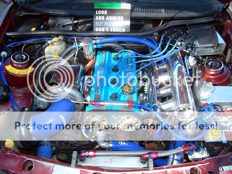
If you look closely, the inlet seems to be at the middle.
As JesseT said
, the intake to the plenum IS in the middle. The Intake manifold spent more time on the flow bench then it took to make. Yes the flow threw the runners are very very close. There are dividers within the "elbow" to deflect the air to runners 1,4. See here for the performance of the Intake manifold combined with the rest of my engine spec.https://passionford.com/forum/viewtopic.php?t=151775

Thread
Thread Starter
Forum
Replies
Last Post
Stu @ M Developments
General Car Related Discussion.
41
Aug 21, 2015 06:47 AM
ekjim
General Car Related Discussion.
6
Aug 17, 2015 08:57 PM
Zoggon
Ford Sierra/Sapphire/RS500 Cosworth
5
Aug 10, 2015 10:39 AM