
MonK-E's ST170 Project

Thread Starter
I'm Finding My Feet Here Now
Joined: Dec 2017
Posts: 124
Likes: 13
From: East Sussex
Haha yeah living the dream my friend, living the dream.
To be honest if it was all just plug and play I’d be bored, although I do get frustrated with certain issues I wouldn’t want it any other way. I love the challenge and rewards of finally working it out
To be honest if it was all just plug and play I’d be bored, although I do get frustrated with certain issues I wouldn’t want it any other way. I love the challenge and rewards of finally working it out
Thread Starter
I'm Finding My Feet Here Now
Joined: Dec 2017
Posts: 124
Likes: 13
From: East Sussex
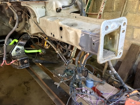
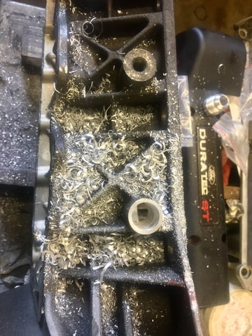
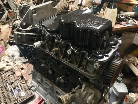
Saturday morning I decided to have a minor clear up around the ramp
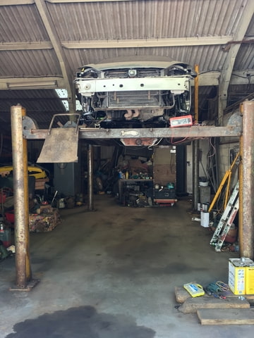
then this happened in the afternoon.
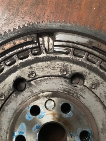
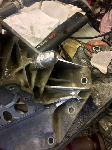
i had a quick look at the stock dmf, which is completely shot.
It moves about 10mm with out any resistance and has 1-2mm side play.
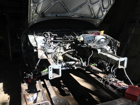
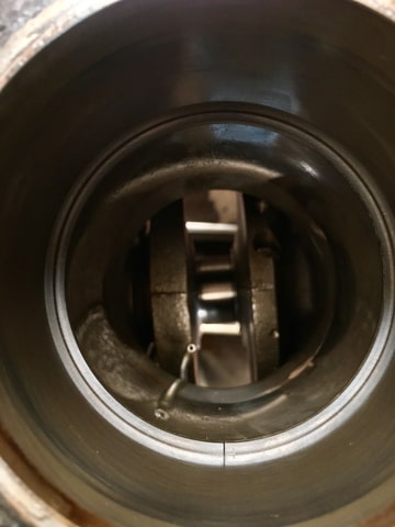
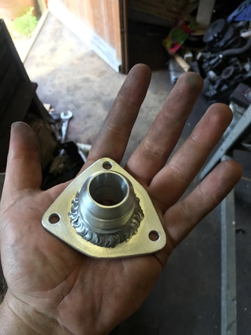
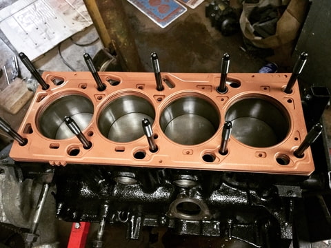
Hears a better pic of what I was saying about the possible interference on the 36-1 trigger wheel and what’s behind it.
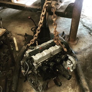
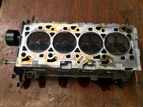
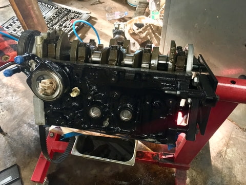
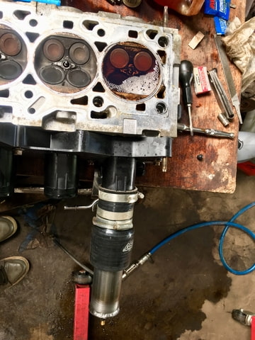
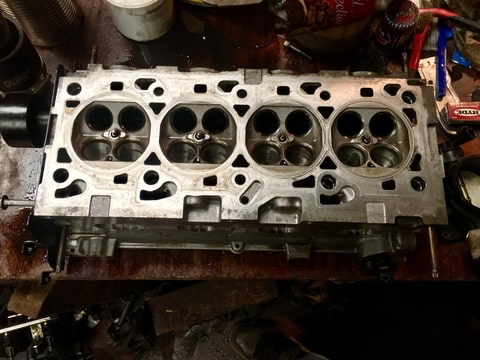
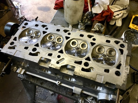
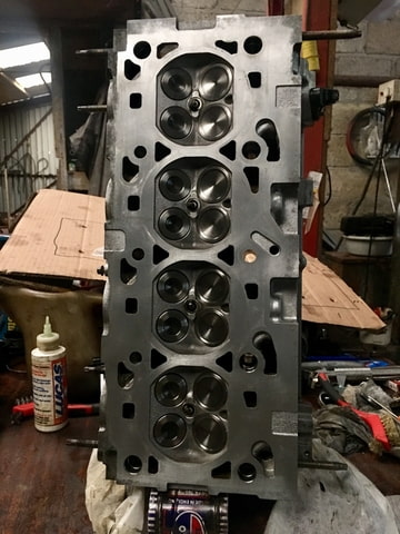
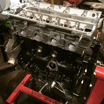
today I whipped the auxiliaries off and mounted the engine on a engine stand.
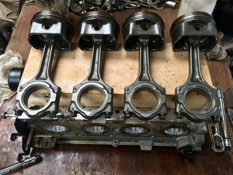
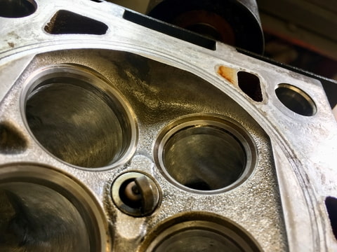
It makes it so much easier to work round. So I got the head off, nothing looking out of the ordinary here but I’ll revisit it later at some point for a more in-depth look.
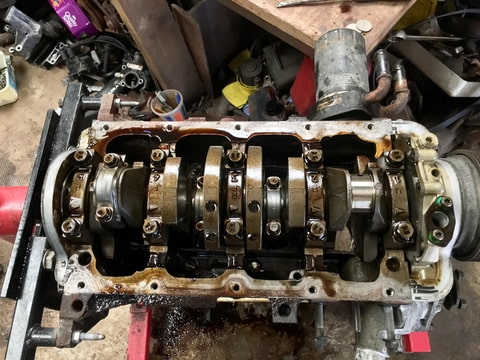
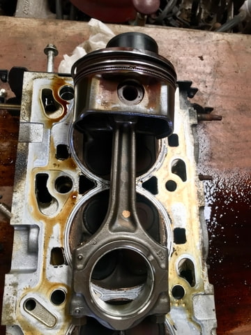
Popped piston and rod 1 out. Looking good so far, next to no wear on it the bigend shells.
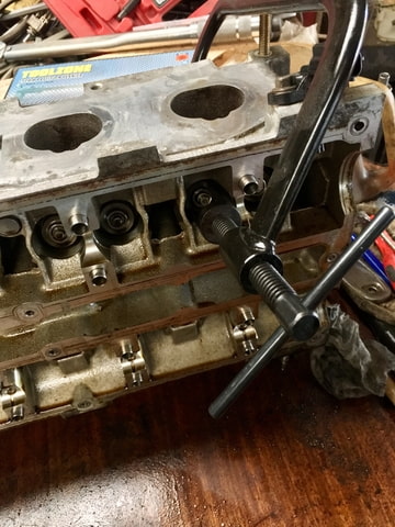
however the oil control rings seem to have seized, most likely due to being sat there for the last 6months. Not a problem though a clean up and refit will sort them out.
the bores look in good condition with no feel-able step on the top compression ring.
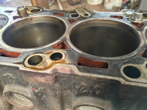
The only way to really tell is to measure them with a dial bore gauge.
So that’s exactly what I did. Bearing in mind the his engine has nearly 80k miles on it.
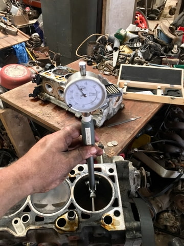
this shows that bore has a deviation of 0.005mm or 0.00019” from top to bottom.
I’m not sure what the zetec specs are but generally for a rehone 0.025mm/0.001” would be an acceptable tolerance.
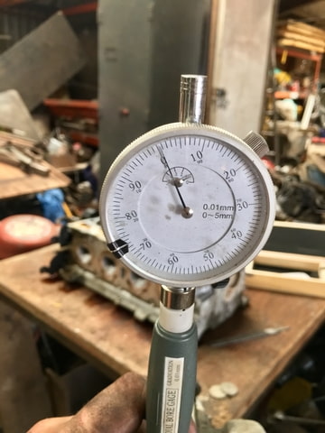
i also measured where the top compression ring sits at TDC as this is a high wear area.
0.01mm/0.00039 well within acceptable to me even if it was freshly honed.
i measured a few other bores and the had even less deviation so I think this should be a bloody good engine. I’ll most likely clean it up re gap the rings and throw it back together with some ARP goodness to try and hold it in shape.
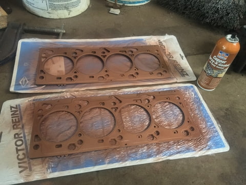
On another note some paint turned up, so I thought I’d brush on a small test patch to get a idea of what’s to come later on.
then this happened in the afternoon.
i had a quick look at the stock dmf, which is completely shot.
It moves about 10mm with out any resistance and has 1-2mm side play.
Hears a better pic of what I was saying about the possible interference on the 36-1 trigger wheel and what’s behind it.
today I whipped the auxiliaries off and mounted the engine on a engine stand.
It makes it so much easier to work round. So I got the head off, nothing looking out of the ordinary here but I’ll revisit it later at some point for a more in-depth look.
Popped piston and rod 1 out. Looking good so far, next to no wear on it the bigend shells.
however the oil control rings seem to have seized, most likely due to being sat there for the last 6months. Not a problem though a clean up and refit will sort them out.
the bores look in good condition with no feel-able step on the top compression ring.
The only way to really tell is to measure them with a dial bore gauge.
So that’s exactly what I did. Bearing in mind the his engine has nearly 80k miles on it.
this shows that bore has a deviation of 0.005mm or 0.00019” from top to bottom.
I’m not sure what the zetec specs are but generally for a rehone 0.025mm/0.001” would be an acceptable tolerance.
i also measured where the top compression ring sits at TDC as this is a high wear area.
0.01mm/0.00039 well within acceptable to me even if it was freshly honed.
i measured a few other bores and the had even less deviation so I think this should be a bloody good engine. I’ll most likely clean it up re gap the rings and throw it back together with some ARP goodness to try and hold it in shape.
On another note some paint turned up, so I thought I’d brush on a small test patch to get a idea of what’s to come later on.
Last edited by MonK-E; Jul 16, 2018 at 02:47 PM.

I've found that life I needed.. It's HERE!!
Joined: Jan 2012
Posts: 1,055
Likes: 126
From: Linc's
The oil controls rings where gummed up on my st bottom end. I put it down to cheap oil being used ?
If your keeping the 6 speed take a look at a ttv single mass fly.
If your keeping the 6 speed take a look at a ttv single mass fly.
Last edited by big_wasa; Jul 16, 2018 at 11:28 AM.
Thread Starter
I'm Finding My Feet Here Now
Joined: Dec 2017
Posts: 124
Likes: 13
From: East Sussex
👍 already have a TTV flywheel on order, as no one has them in stock at the moment so it could be a couple of weeks before it turns up. That�s ok though as I�ve got plenty to get on with in the mean time


Thread Starter
I'm Finding My Feet Here Now
Joined: Dec 2017
Posts: 124
Likes: 13
From: East Sussex

Thread Starter
I'm Finding My Feet Here Now
Joined: Dec 2017
Posts: 124
Likes: 13
From: East Sussex
Thread Starter
I'm Finding My Feet Here Now
Joined: Dec 2017
Posts: 124
Likes: 13
From: East Sussex
It is a bit of a shame to put really well machined parts in places that never really see the light of day but it�s good piece of mind knowing they are there and put up with untold amounts of abuse
Thread Starter
I'm Finding My Feet Here Now
Joined: Dec 2017
Posts: 124
Likes: 13
From: East Sussex
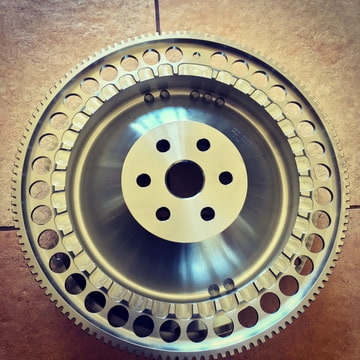
Yeah, I’ve never tried one before so not sure what to expect. In theory it’s a good idea but I’ll have to see what it’s like. If it doesn’t work to great I’ll have to go for a paddle clutch.
This little gem turned up today. A lot sooner than I expected, nice little surprise when it got in from work
This little gem turned up today. A lot sooner than I expected, nice little surprise when it got in from work
Thread Starter
I'm Finding My Feet Here Now
Joined: Dec 2017
Posts: 124
Likes: 13
From: East Sussex
Spent pretty much all day cleaning and gapping rings.
Standard ring gaps were
0.012” for the top ring
0.035” for second ring
0.018” for the oil scrapers
I decided to open up the top ring by 6 thou. The second ring is plenty big enough and the oil control rings are fine.
So now they are all set to
0.018” top
0.035” second
0.018” oil
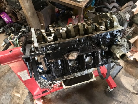
I also cleaned up the block a bit and gave it a nice coat of engine enamel
Standard ring gaps were
0.012” for the top ring
0.035” for second ring
0.018” for the oil scrapers
I decided to open up the top ring by 6 thou. The second ring is plenty big enough and the oil control rings are fine.
So now they are all set to
0.018” top
0.035” second
0.018” oil
I also cleaned up the block a bit and gave it a nice coat of engine enamel
Thread Starter
I'm Finding My Feet Here Now
Joined: Dec 2017
Posts: 124
Likes: 13
From: East Sussex
cheers bud, it is very well machined, it�ll definitely be a shame to lock it away in a bellhousing. But hey it�s there to do a job. Fingers crossed it�ll all work well with the clutch.
I do need to find a replacement pressure plate though. The stock one has heat cracks in it where it�s been slipping a fair amount
I do need to find a replacement pressure plate though. The stock one has heat cracks in it where it�s been slipping a fair amount
Thread Starter
I'm Finding My Feet Here Now
Joined: Dec 2017
Posts: 124
Likes: 13
From: East Sussex
I couldn’t find my piston ring compressor. I haven’t used it for a bout a year and it seems in that time it’s grown legs and walked off somewhere.
Anyway I wasn’t going to let this stop me so I put my redneck hat on and found a fox’s biscuit tin to cut up.
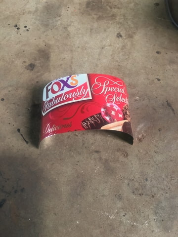
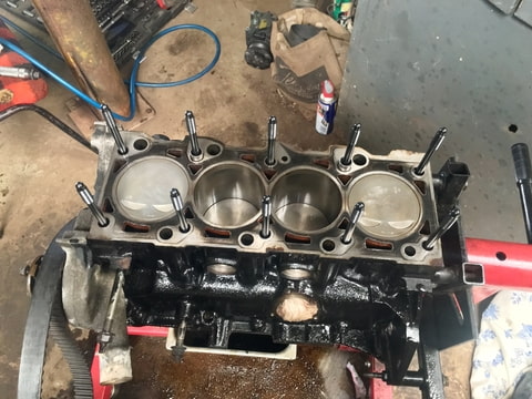
put a jubilee clip round it and there we go. 1 home brew piston ring compressor
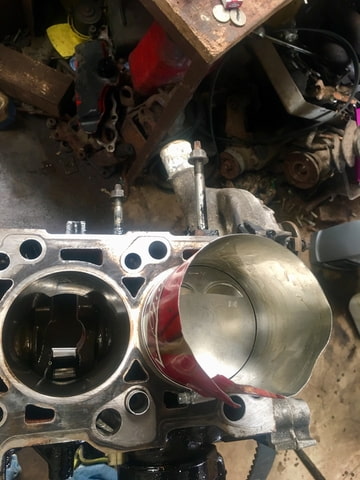
torqued up the set of ARP rod bolts
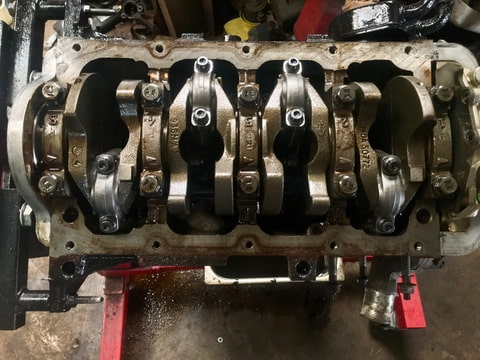
then wound the head studs in
I did want to pressure test the intake ports and see at what point they leak but that’ll have to wait until next weekend now as I ended up having to go on a rescue mission
Anyway I wasn’t going to let this stop me so I put my redneck hat on and found a fox’s biscuit tin to cut up.
put a jubilee clip round it and there we go. 1 home brew piston ring compressor
torqued up the set of ARP rod bolts
then wound the head studs in
I did want to pressure test the intake ports and see at what point they leak but that’ll have to wait until next weekend now as I ended up having to go on a rescue mission


Thread Starter
I'm Finding My Feet Here Now
Joined: Dec 2017
Posts: 124
Likes: 13
From: East Sussex
Didn�t do a great deal today, but progress is progress 
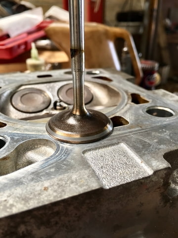
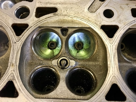
I started off with pressure testing the intake port to see at what pressure the inlet valves start to leak.
At 10psi they were weeping
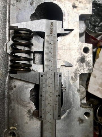
I was as thinking the springs can�t possibly be that weak so I whipped the 2 inlet valves out and lapped them in
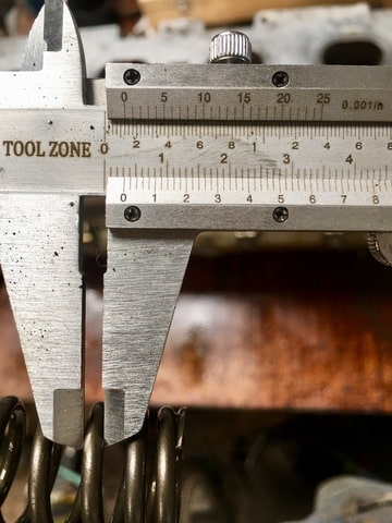
while the springs were out I measured them just in case this doesn�t work out and I need some uprated ones. 45.40mm x 3.28mm
After spending a few minutes what feels like trying to start a campfire with a stick and sucker plus some lapping paste I ended up with this
also used this little trick when putting the collets back in. It saves a lot of frustration
Anyway with the valves back in and the intake manifold back on, I splashed a bit of diesel in the combustion chamber and proceeded with the retest.
10psi no leak
20psi no leak
30psi no leak
40psi no leak
50psi blew the silicone joiner off the manifold.
I decided to leave it there because realistically I�ll probably only get to run half that boost pressure on standard rods.
at least I know the valve springs are up to the job. I�ll have to spend a fair while lapping the lot in. But now I�m wondering if I should give the ports a quick port and polish when I have all the valves out.
I know it�s not going to make a great deal off difference but every little an all that. Plus it�s a bit rude not too when all the valves are out isn�t it
I started off with pressure testing the intake port to see at what pressure the inlet valves start to leak.
At 10psi they were weeping
I was as thinking the springs can�t possibly be that weak so I whipped the 2 inlet valves out and lapped them in
while the springs were out I measured them just in case this doesn�t work out and I need some uprated ones. 45.40mm x 3.28mm
After spending a few minutes what feels like trying to start a campfire with a stick and sucker plus some lapping paste I ended up with this
also used this little trick when putting the collets back in. It saves a lot of frustration
Anyway with the valves back in and the intake manifold back on, I splashed a bit of diesel in the combustion chamber and proceeded with the retest.
10psi no leak
20psi no leak
30psi no leak
40psi no leak
50psi blew the silicone joiner off the manifold.
I decided to leave it there because realistically I�ll probably only get to run half that boost pressure on standard rods.
at least I know the valve springs are up to the job. I�ll have to spend a fair while lapping the lot in. But now I�m wondering if I should give the ports a quick port and polish when I have all the valves out.
I know it�s not going to make a great deal off difference but every little an all that. Plus it�s a bit rude not too when all the valves are out isn�t it
Last edited by MonK-E; Jul 28, 2018 at 07:01 PM.
Thread Starter
I'm Finding My Feet Here Now
Joined: Dec 2017
Posts: 124
Likes: 13
From: East Sussex
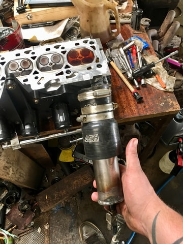
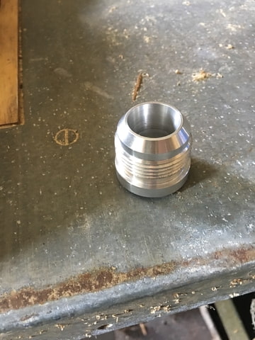
I purchased some an20 fittings in some strange attempt in thinking they would do for the engine breather upgrade. I didn’t really think that through until they turned up and realised exactly how big an20 is.
An20 along side an16
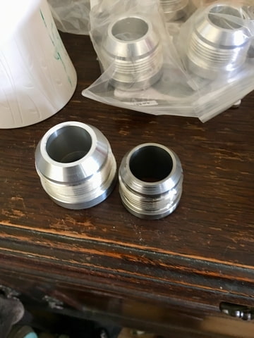
luckily I purchased some aluminium an16 at the same time, which is what I’ll use for the breathers.
I fabricated a small plate the shape of the crankcase breather mount and tig welded it on, excuse the poor weld. Haven’t tig’d aluminium for a good 6 months and I wasn’t exactly good at it in the first place. However it’ll do the job just fine.
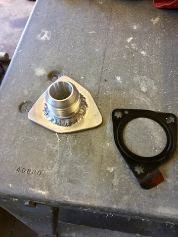
then I poked some holes in it and that’s that little job off the huge list of things to get done
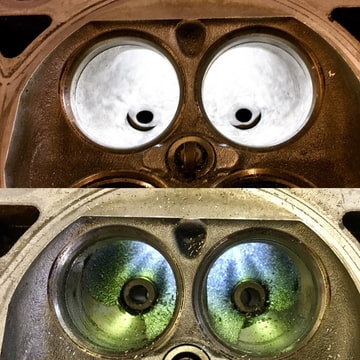
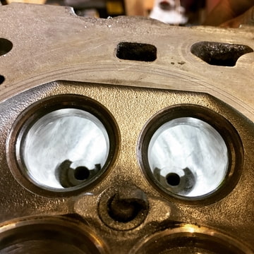
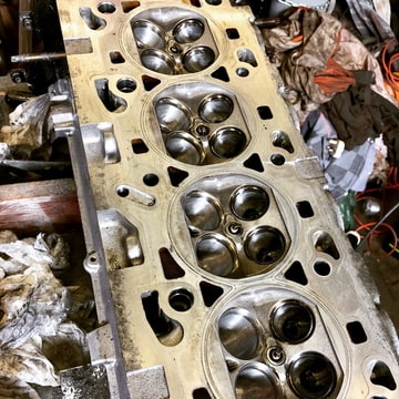
as planned I started porting and polishing the head. Nothing really to shout about it’s only a mild port to help things along a bit.
As you can see very little taken out of the intake port. A small amount by the divider and a general clean up to remove the rough casting. Most of the work on these heads are around the valve bowls.
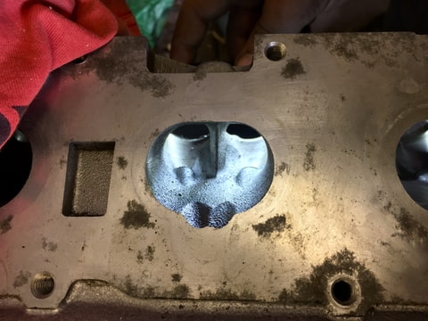
A bit of reshaping done and opened out a small fraction. But as said it’s just a mild port so nothing special.

Well that’s 1 port done 7 more to go but I’ve got to wait for more flap wheels to turn up for the little remote dremel to continue.
I’ve completely forgot how long it takes to do this with the tools I have since doing the last head. Still it doesn’t really matter how long I spend on it. It’s a labour of love after all
An20 along side an16
luckily I purchased some aluminium an16 at the same time, which is what I’ll use for the breathers.
I fabricated a small plate the shape of the crankcase breather mount and tig welded it on, excuse the poor weld. Haven’t tig’d aluminium for a good 6 months and I wasn’t exactly good at it in the first place. However it’ll do the job just fine.
then I poked some holes in it and that’s that little job off the huge list of things to get done
as planned I started porting and polishing the head. Nothing really to shout about it’s only a mild port to help things along a bit.
As you can see very little taken out of the intake port. A small amount by the divider and a general clean up to remove the rough casting. Most of the work on these heads are around the valve bowls.
A bit of reshaping done and opened out a small fraction. But as said it’s just a mild port so nothing special.
Well that’s 1 port done 7 more to go but I’ve got to wait for more flap wheels to turn up for the little remote dremel to continue.
I’ve completely forgot how long it takes to do this with the tools I have since doing the last head. Still it doesn’t really matter how long I spend on it. It’s a labour of love after all

Thread Starter
I'm Finding My Feet Here Now
Joined: Dec 2017
Posts: 124
Likes: 13
From: East Sussex
hahaha I really don�t know what I was thinking with that. Although a an20 would of just about fit the opening in the crankcase. I doubt there would be enough room for the 90 degree fitting to go between the exhaust. I could place the exhaust further away but then it�ll be too close to the rad.
The reason I want to run a large breather is that I�ve opened up the ring gaps and want to run reasonably high boost so I�m expecting more blowby. A buildup of crankcase pressure is never a good thing, it�s easy to prevent now with large fittings and a catch can than have to replace the lot later on down the line if I run into breathing issues.
The reason I want to run a large breather is that I�ve opened up the ring gaps and want to run reasonably high boost so I�m expecting more blowby. A buildup of crankcase pressure is never a good thing, it�s easy to prevent now with large fittings and a catch can than have to replace the lot later on down the line if I run into breathing issues.
Thread Starter
I'm Finding My Feet Here Now
Joined: Dec 2017
Posts: 124
Likes: 13
From: East Sussex
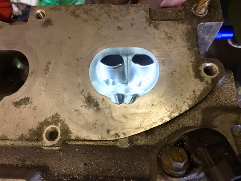
Just done a bit more porting this weekend. Andrew from A.L.D. Commented on one of my FB pics and showed me how much I could take out of the ports. I wasn’t going to take any more out but as I was doing it, I thought ahhh well in for a penny, in for a pound.
Heres what they look like now
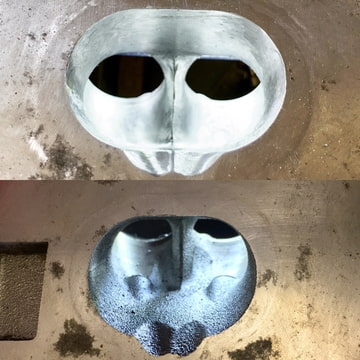
that just about does it for the intake ports. No where near as much work to do on the exhaust ports so hopefully they will be a bit quicker
Heres what they look like now
that just about does it for the intake ports. No where near as much work to do on the exhaust ports so hopefully they will be a bit quicker
Thread Starter
I'm Finding My Feet Here Now
Joined: Dec 2017
Posts: 124
Likes: 13
From: East Sussex
Thanks bud
in theory it should make a little bit more power with less boost. Which means lower charge temp and a happier engine. I would say safer but there’s not much safety in abusing standard rods and pistons.
We shall see though it’ll be interesting either way
in theory it should make a little bit more power with less boost. Which means lower charge temp and a happier engine. I would say safer but there’s not much safety in abusing standard rods and pistons.
We shall see though it’ll be interesting either way
Thread Starter
I'm Finding My Feet Here Now
Joined: Dec 2017
Posts: 124
Likes: 13
From: East Sussex
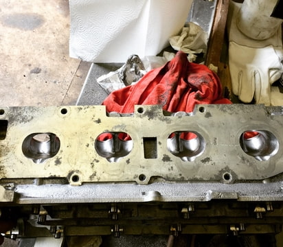
I carried on with finishing off the port work.
Done the exhaust ports. Not a great deal to do with them again most of the work was in the bowl area. I didn’t want to take much out of the exhaust ports as the wall thickness in some areas seems quite thin. The water jacket runs right through the centre devider as well.
that’s pretty much it for porting
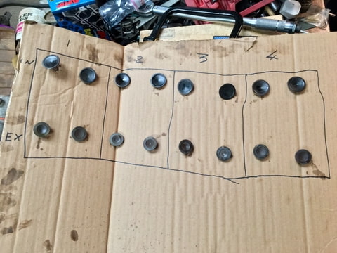
on to the valves, got to love how ford stamps everything
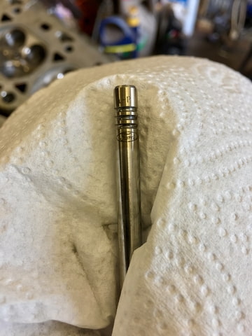
spent a little while cleaning them all up
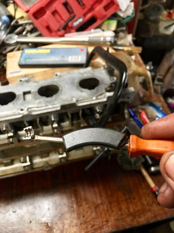
and on to lapping them all in. I’ve allways done these by hand previously and it takes forever.
I wasn’t relishing the idea this time so I decided to cheat with a battery drill, a small piece of silicone pipe and a bolt
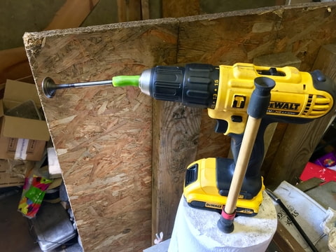
It made really lite work of the seats, definitely will be using this little cheat method again
there we go all the valves lapped in
next weekend I’m going to try another little cheat as all the valve clearances will need doing and I’m far to tight to go out and buy 16 new buckets. Could be interesting as it involves a circular saw and a workmate ��
Done the exhaust ports. Not a great deal to do with them again most of the work was in the bowl area. I didn’t want to take much out of the exhaust ports as the wall thickness in some areas seems quite thin. The water jacket runs right through the centre devider as well.
that’s pretty much it for porting
on to the valves, got to love how ford stamps everything
spent a little while cleaning them all up
and on to lapping them all in. I’ve allways done these by hand previously and it takes forever.
I wasn’t relishing the idea this time so I decided to cheat with a battery drill, a small piece of silicone pipe and a bolt
It made really lite work of the seats, definitely will be using this little cheat method again
there we go all the valves lapped in
next weekend I’m going to try another little cheat as all the valve clearances will need doing and I’m far to tight to go out and buy 16 new buckets. Could be interesting as it involves a circular saw and a workmate ��
Last edited by MonK-E; Aug 18, 2018 at 05:44 PM.
Thread Starter
I'm Finding My Feet Here Now
Joined: Dec 2017
Posts: 124
Likes: 13
From: East Sussex
Time for a bit of a update
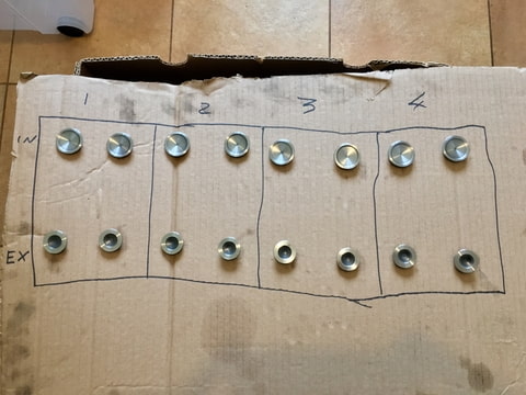
I decided against using a circular saw and used my metal cut off saw. Just took apart the jaws and bolted a v clamp to the bed. With the blade locked down it worked a treat for taking of 1 thou at a time
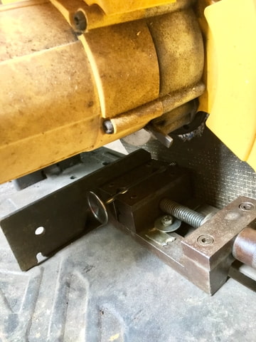
i only had to skim 6 valve stems as the rest were still well within tolerance. So all new valve stem seals, a quick wash of the valve springs and retainers. The head is back together
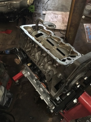
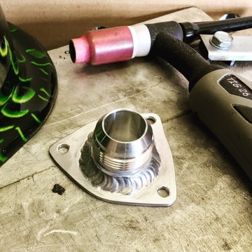
after that I decided to have a look at the top half of the sump. I drilled out one of the spare lugs for the turbo oil return.
then welded a AN12 fitting to it, I also repaired some of the webbing where the previous owner had hacked into it with a cutting disc.
Next I coated both the head gaskets and decomp plate with copper sealer
then layed them on the block
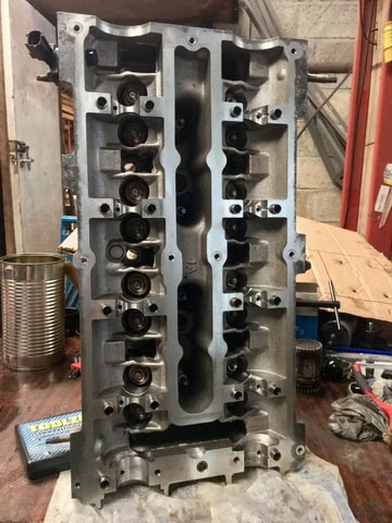
Torqued down the head and installed half of the sump
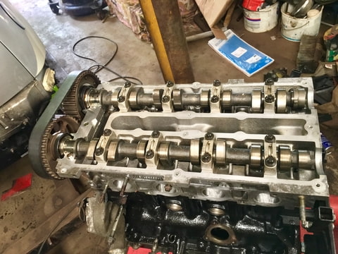
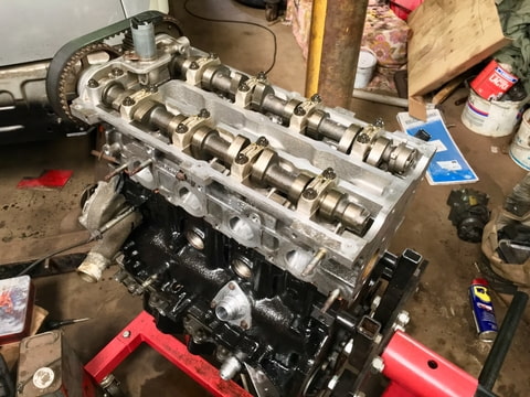
I poped the buckets and cams in, I’ve left off the VVT solenoid for a bit as I need some sealer for it.
I also temporarily slipped the cam belt on. There has been talk that if you raise the head by 3mm or more then you need a 1 tooth longer belt. This isn’t the case as it fits with the standard tensioner although it seems about its limit before its on the tight side.
after that I cleaned up the lower sump, installed it then painted it
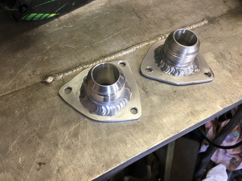
when I go round to fitting the crankcase breather I realised I made it backwards to the gasket. I was sure I got it round the right way but hey obviously not.
So I knocked up a new one.
Just as a comparison, this time I managed to weld it a bit nicer too. Still could do with a lot more practice though.
next up I’ll probably make a start on cleaning the bay I think
I decided against using a circular saw and used my metal cut off saw. Just took apart the jaws and bolted a v clamp to the bed. With the blade locked down it worked a treat for taking of 1 thou at a time
i only had to skim 6 valve stems as the rest were still well within tolerance. So all new valve stem seals, a quick wash of the valve springs and retainers. The head is back together
after that I decided to have a look at the top half of the sump. I drilled out one of the spare lugs for the turbo oil return.
then welded a AN12 fitting to it, I also repaired some of the webbing where the previous owner had hacked into it with a cutting disc.
Next I coated both the head gaskets and decomp plate with copper sealer
then layed them on the block
Torqued down the head and installed half of the sump
I poped the buckets and cams in, I’ve left off the VVT solenoid for a bit as I need some sealer for it.
I also temporarily slipped the cam belt on. There has been talk that if you raise the head by 3mm or more then you need a 1 tooth longer belt. This isn’t the case as it fits with the standard tensioner although it seems about its limit before its on the tight side.
after that I cleaned up the lower sump, installed it then painted it
when I go round to fitting the crankcase breather I realised I made it backwards to the gasket. I was sure I got it round the right way but hey obviously not.
So I knocked up a new one.
Just as a comparison, this time I managed to weld it a bit nicer too. Still could do with a lot more practice though.
next up I’ll probably make a start on cleaning the bay I think
Thread Starter
I'm Finding My Feet Here Now
Joined: Dec 2017
Posts: 124
Likes: 13
From: East Sussex
Cheers bud, the internals are pretty spotless. The aluminium casings aren’t the best though.
I did also try welding a AN fitting to the cam cover but it didn’t want to hold and kept cracking over and over again. Needles to say I got rather flustered with it and launched it down the garden into a concrete shed. It now resides in a few parts (that’ll teach me for having a paddy)
fortunately I’ve been able to get hold of another one through FB. I might forgo the AN fitting on the cam cover this time round haha

Advanced PassionFord User
Joined: May 2011
Posts: 2,419
Likes: 272
From: God knows!
Thread Starter
I'm Finding My Feet Here Now
Joined: Dec 2017
Posts: 124
Likes: 13
From: East Sussex
Hahaha, anyone who welds thin cast aluminium knows the pure rage that is brought on by hot cracking. Normally I’m very calm and collected, very very few things can push me to a violent out burst.
Thanks for the link but I already have one on its way
Thanks for the link but I already have one on its way
Thread Starter
I'm Finding My Feet Here Now
Joined: Dec 2017
Posts: 124
Likes: 13
From: East Sussex
It�s around 8:1, iirc the piston crown cc is around 6cc and the head is known to be 42cc. That�s with a standard gasket squashed to 1mm + 2mm decomp plate + another standard squashed gasket. I ended up using a online calculator for most of the maths as I�m backwards with lots of sums
Thread Starter
I'm Finding My Feet Here Now
Joined: Dec 2017
Posts: 124
Likes: 13
From: East Sussex
I fitted the VVT solenoid and crank case breather today
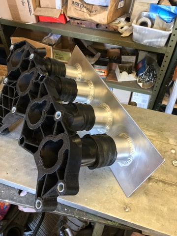
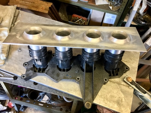
Then made a start on fabricating the intake mani
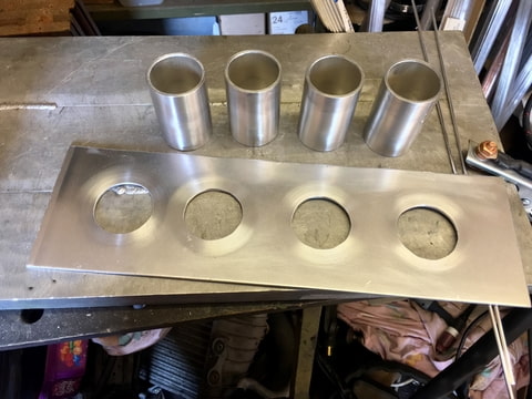
Managed to weld up the first runner
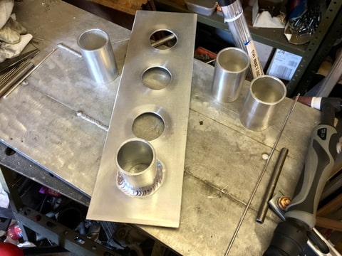
I’ve not fabricated a aluminium mani before so this could be interesting. Hopefully I’ll get the rest of them welded up this weekend if I don’t run out of argon first lol
Then made a start on fabricating the intake mani
Managed to weld up the first runner
I’ve not fabricated a aluminium mani before so this could be interesting. Hopefully I’ll get the rest of them welded up this weekend if I don’t run out of argon first lol
Last edited by MonK-E; Sep 1, 2018 at 05:14 PM.
Thread Starter
I'm Finding My Feet Here Now
Joined: Dec 2017
Posts: 124
Likes: 13
From: East Sussex
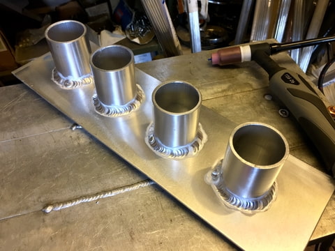
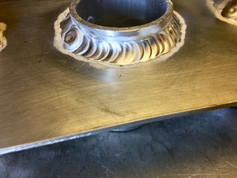
I finished welding up the out side of the runners. I was a bit concerned about torch angle in between the runners (one of them is quite tight). With welding aluminium if the angle wanders it causes all kinds of Issues with the weld. Luckily I think I got away with it though
Then started work on the inside of the plenum
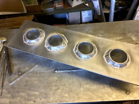
I wasn’t fussed with the finish of the welds on the inside as they will be sanded back for smoother flow, which gave me the opportunity to play with the weld puddle a bit lol. My first attempt at a aluminium weave.
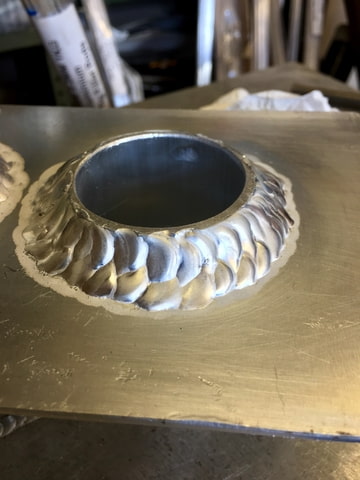
Any way after that I die grinded the inside of the runners to add a taper to them, then sanded the welds back
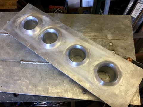
That’s about it for now as I’ve completely run out of argon and I’ll have to wait until next payday before I can afford any more ����

Woot for 100th post lol
Then started work on the inside of the plenum
I wasn’t fussed with the finish of the welds on the inside as they will be sanded back for smoother flow, which gave me the opportunity to play with the weld puddle a bit lol. My first attempt at a aluminium weave.
Any way after that I die grinded the inside of the runners to add a taper to them, then sanded the welds back
That’s about it for now as I’ve completely run out of argon and I’ll have to wait until next payday before I can afford any more ����
Woot for 100th post lol
Last edited by MonK-E; Sep 2, 2018 at 06:25 PM.