When you click on links to various merchants on this site and make a purchase, this can result in this site earning a commission. Affiliate programs and affiliations include, but are not limited to, the eBay Partner Network.
General Car Related Discussion.To discuss anything that is related to cars and automotive technology that doesnt naturally fit into another forum catagory.
right I'm refreshing my wiring loom and extending parts to try and tuck it away to be seen less. Has been a while since I've been at my loom so just wanted to check that what I think is right is actually correct lol
Its an rs turbo OFAC loom changed the loom plug over for me so plugs straight into my interior loom (mk3,5)
I'm going to b using an OFAM ecu which has a internal map sensor so I won't need my standard map sensor correct? Also I don't think il need the co2 pot either. From what I can gather all I need to keep is the edis module the new ecu controls the rest
o I've got the following
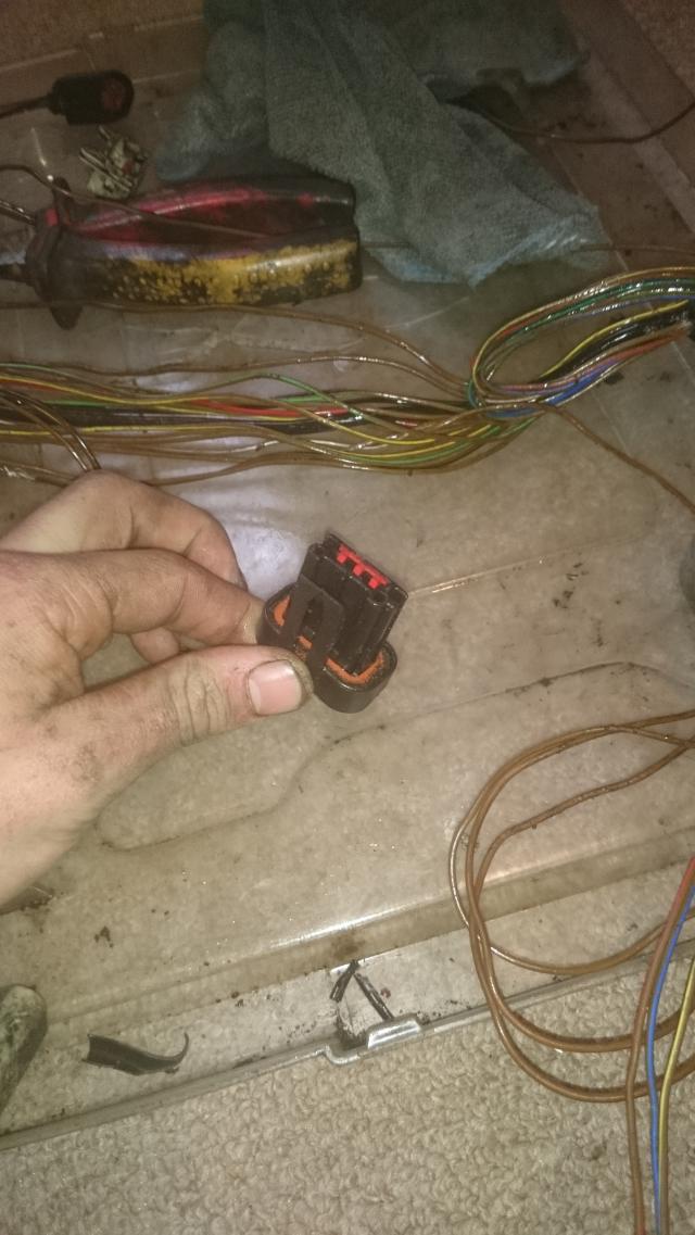
1-2 pin plug that I think plugs into the boost solenoid
Green and brown wire, solid black wire
2-oil pressure switch plug 1 green&brown wire
3- not sure what this one is 2 pin plug,brown&yellow and a solid black wire
4- coil pack plug
5- pretty sure this is the edis plug
6- this goes off to the crank sensor
7-i think this is the map sensor plug
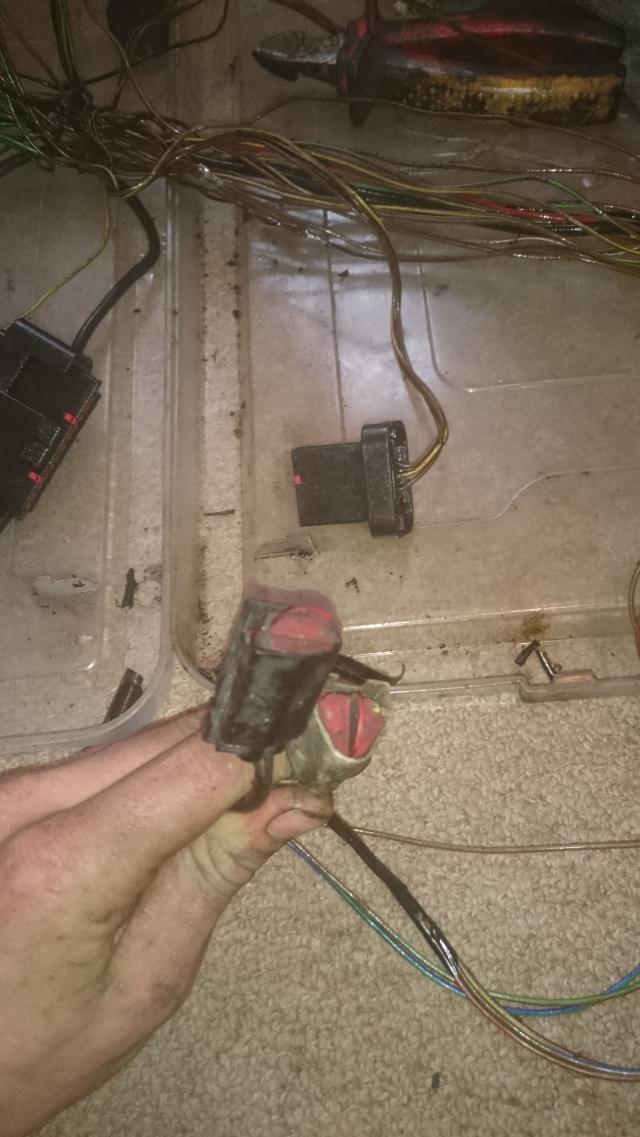
8-theres 2 plugs here that have always been blanked off and obsolete can I just trace these back and chop out?
9- this is the loom plug that plugs the interior loom to engine loom
10-this is the plug that joins to the injectors loom
11- triangle 3 pin plug pretty sure this is the gearbox speed sensor
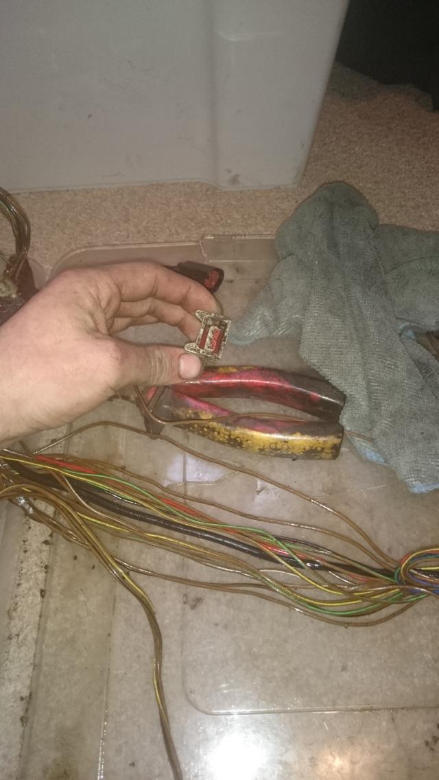
12- this is a 3 pin plug (white) I don't know where this should go either?
13- engine earth
There is another earth outside of the picture
I can try and check on mine on Thursday when I can get in the garage. I'm on my phone but could probably identify some connections. When I get to a Pc I'll let you know.
Are you still struggling with this? You can ditch the standard MAP sensor and CO POT or diagnostics connectors. However have a good look at the pinout, the OFAM uses standard wiring for some of the prog outputs. For example the standard AMAL valve wiring (if you have it) is the boost output, some of the diag connectors also have optional outputs for things like fan control etc.
Are you still struggling with this? You can ditch the standard MAP sensor and CO POT or diagnostics connectors. However have a good look at the pinout, the OFAM uses standard wiring for some of the prog outputs. For example the standard AMAL valve wiring (if you have it) is the boost output, some of the diag connectors also have optional outputs for things like fan control etc.
Happy to give advice if you get stuck
Rob,
Hi, thanks very much for the reply! Yes still struggling.not having much in the engine bay makes.it difficult to work out what plugged into what lol.. Right ok so I can do away with the co2 pot and map sensor sweet, I remember the co2 pot being a 2 pin plug I think it's the white plug pictured but not 100%
Right ok that's useful to know! Don't suppose you could point me in the direction of a wiring diagram for these? I do still have the wiring for the amal valve but the hot exam valve itself is long gone lol I'd assume this is if I want to use the ecu for EBC?
If I can figure out which plugs are which and if I need or don't need some parts/wiring in the bay if be a happy man! Just don't want to remove something il later wish I hadn't lol
Thanks
Russ
Im not sure what car you are installing this into so apologies if this doesn't answer your question in one hit, also are you trying to minimise wires in the loom or rebuild it to suit another car? I'll answer assuming the latter for now.
Firstly, and I cannot stress this enough. The condition and location of earthing wires is critical. These should be individual wires from the ecu to a single point (a star ground) which ideally should be somewhere on the engine block. The engine block will need a good connection to the battery neg terminal with an earthing strap from either the batter terminal to car body, or slightly better the block to car body.
The EDIS unit should be well grounded to the engine block as well.
Now, the standard ford ECU used a permanent 12v (keep alive) feed to pin 1 on the ecu, this wire is red and the OFAM does not use it. We only use the switched live (from memory this is pin 27 but yout pin out diagram will tell you more), so to power the ecu this switched live comes from the main relay via a 5A fuse.
Connections you need to keep are as follows (from the top of my head):
Coolant temp.
Manifold temp.
Amal wiring (not strictly needed but may as well).
All wiring to and from the edis unit (SAW and PIP wiring, usually shielded cable, earth at ecu end only, tach wiring and tach suppressor).
Fuel pump control wire
Throttle position.
The injector wiring.
All bits are not used, all of the diag connectors (there are two with red plugs in them I think), the CO pot, the MAP sensor etc.
Remember through that the loom has bit in there still needed such as a switched 12v feed to ignition coil, EDIS module, injectors etc.
With regard to boost control, the AMAL valve can probably be used however I have always used a modern valve instead such as a MAC valve or Vauxhall VXR/VAG boost control valve, these are fairly cheap and have two connections requiring only a connector change at most. One of the two wires is 12v switched and it doesn't matter which way round it is connected.
Hope that helps a little, also the CO pot connector is a two pin junior power timer connector, usually black I think? I recommend using the OFAM pinout diagram and buzzing through all the wiring when your done to make sure you still have all the needed bits. I will have a hunt for a standard wiring diagram... Im sure I have one somewhere.
Also if it helps, the CO pot, EDIS unit and MAP sensor are all mounted on the same plate in the engine bay so the wire length to these three will be pretty similar.
Hi it's being fitted into my mk3.5 fiesta with a zetec turbo.engine
Just trying to.minimise the loom so I can tuck majority of.it away to look cleaner,
Right make.sure the earth's are good that's fine, iv got a few of those braided earth straps fitted atm running.from engine to the shell and she'll to battery, plus either 2 or 3 earth's are in the engine loom...
Will the loom earth the edis ok enough or is it worth me running a separate earth strap from.the edis plate to the engine?
Right that list of what I need to.keep.is perfect! I was thinking about removing the plugs and wires for map sensor etc but I I may just keep them in if it's not straight forwards plus where iv routed the loom you can't see them anyway.
As regards to the OFAM pinout diagram am.I supposed to.have this with my ecu or is that on.your site? (I haven't loaded any software onto a laptop yet so excuse me if it's on tha)
Many thanks
Russ
Last edited by Smidydevil; 12-02-2015 at 05:13 PM.
Plug one is for the boost solenoid
Plug three is the idle speed control valve
Plugs eight are diagnostic ports so not required
Plug twelve is the co pot.
The rest you have correctly identified by the looks of it.
As above also I was wrong the CO pot connector is white not black. Also the pin out diagram is on the disk. I would also suggest leaving provision for a wide band lambda in you loom if you are tucking it away, better than trying to add one later!
Also, no the EDIS earth in the loom will be fine, given the choice however I would always suggest having a decent earth direct from engine block to battery rather than to shell then to block, you ideally want the lowest resistance connection to the system ground as you can manage.
This doesn't really help you but why did you choose an OFAM instead of a GEN8 as it looks like you are essentially making the loom up anyway, surely that would have been a much easier route benefiting from brand new wiring too?
Plug one is for the boost solenoid
Plug three is the idle speed control valve
Plugs eight are diagnostic ports so not required
Plug twelve is the co pot.
The rest you have correctly identified by the looks of it.
As above also I was wrong the CO pot connector is white not black. Also the pin out diagram is on the disk. I would also suggest leaving provision for a wide band lambda in you loom if you are tucking it away, better than trying to add one later!
Also, no the EDIS earth in the loom will be fine, given the choice however I would always suggest having a decent earth direct from engine block to battery rather than to shell then to block, you ideally want the lowest resistance connection to the system ground as you can manage.
Thanks yes I thought this whilst browsing.through old photos showing the co2pot with a white.plug. Ahh ok that'd be why I haven't found a.pin.out then lol that is a very good point! Thanks for mentioning that
Right ok one earth strap straight from.the block to the engine will be fitted then
Thanks very much for your help
This doesn't really help you but why did you choose an OFAM instead of a GEN8 as it looks like you are essentially making the loom up anyway, surely that would have been a much easier route benefiting from brand new wiring too?
Fair question, erm according to their website gen8 isn't on sale yet? Plus in my eyes I don't see them being much different? I think you are under the impression I'm doing more to my loom than I actually am lol I bought OFAM originally so I could just whack.it in the hole and plug it in no questions, no messinget,no wiring job done. When I removed my loom obviously being an old loom the loom tape was in poor condition somebody at some.point has "repaired" it with connectors and such and a couple of the plug connections were a little loose, iv just essentially stripped out anything that has looked suspect and replaced.with new cable soldered and heat shrinked in, and then just extended.certain plugs a few.inches to make it easier to tuck the loom.where I want it, this plus cleaning and re wrapping the loom has made it look all smarter and hopefully will be a bit more reliable and issue free now as we all know old looms are a bit... Worn lol
I wouldn't mind building a loom from scratch if I HAD too but I'm not a massive fan of wiring, capable of doing it but don't.enjoy it lol

 01-02-2015, 03:25 PM


 also I was wrong the CO pot connector is white not black. Also the pin out diagram is on the disk. I would also suggest leaving provision for a wide band lambda in you loom if you are tucking it away, better than trying to add one later!


