When you click on links to various merchants on this site and make a purchase, this can result in this site earning a commission. Affiliate programs and affiliations include, but are not limited to, the eBay Partner Network.
All you can do really is a resistance test on it.
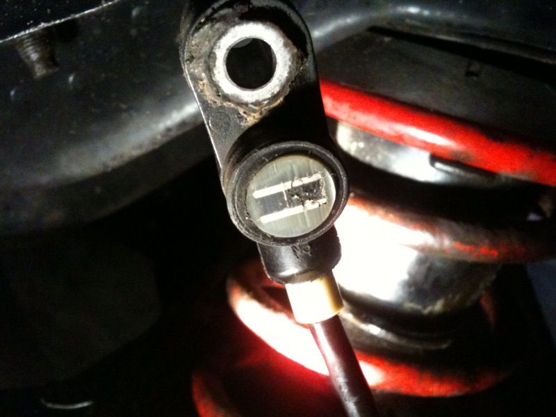
As the sensor merely outputs a square wave signal from the abs ring, any sensor of this type can be used, ie flywheel sensor etc that fits.
tabetha
Measured all sensors, all in area of 1100ohms so ok i think, there was a little difference in volts between left and right at the rear (left is 205mV and right 160mV at aprox 60rpm) and i noticed that the handbrake light sometimes stays on
Any help is welcome guys
Could be unrelated the e brake light, I know on mine I need to run the level around 1/2" ABOVE the max mark when pressurised or the light comes on on corners sometimes, 1/2" above it's fine.
tabetha
Could be unrelated the e brake light, I know on mine I need to run the level around 1/2" ABOVE the max mark when pressurised or the light comes on on corners sometimes, 1/2" above it's fine.
tabetha
Good point as mine always has about a 1/2'' above the level so worth checking
Originally Posted by dojj
you can silicon it back up again but it might be crap in the sensor hole, the erars run without any covers so give it a blast with some wd40
Allready cleaned them out with wd40 and air, also the abs rings
if there is a bit of rust in the ring though it can give the sensor funny readings, but i've found that putting a dollop of greasy grease on the end of the sensor and going for a spin collects most of the loose flakes of crap
The ABS wiring diagram in the standard sierra Haynes manuals is virtually correct for 2wd cars (only some of the earth info is wrong), but it doesn't cover the 4x4 ABS wiring. You should be able to find a copy on the net somewhere.


 25-02-2010, 01:45 PM


