
Map sensor wiring

Thread Starter
Regular Contributor
Joined: Oct 2008
Posts: 284
Likes: 0
From: burton on trent
map sensor wiring variation for the L6 ecu,
pin 30 on ecu goes to (A) on map sensor
pin 11 on ecu goes to (B) on map sensor
pin 15 on ecu goes to (C) on map sensor
according to this schematic of the L6 ECU
Now on the cosworth wiring diagram taken from cannell manuals shows a difference
pin (A) BR-GN goes to pin 11 on ecu
pin (B) RT goes to pin 30 on ecu
pin (C) SW/RT goes to pin 15 on ecu, the burning question is which is correct, As this diagram shows pin (B) as + voltage
the top diagram shows pin 30 on ecu goes to (A) which is positive, very confusing, anyone shed any light on this please.
Last edited by cozi500; Oct 25, 2012 at 05:58 AM.

I've found that life I needed.. It's HERE!!
Joined: Jan 2008
Posts: 1,134
Likes: 25
From: Netherlands
.
Hiya mate, I've got my L6 2wd engine loom on a board (see below) this is correct as per my loom
pin 11=Brown/Green
Pin 15-Brown
pin 30=Brown/Yellow(but T's to a Red @ the ECU plug)
pin 19=earth braiding that is around the other 3 wires
The braid is to reduce noise/interference.
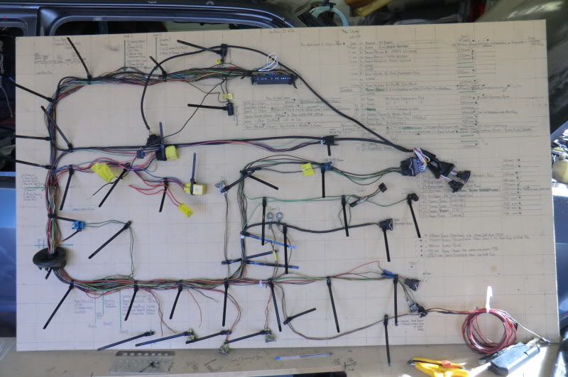
(pins 11, 15 & 19 have 2 wires at the ECU plug)
If you save the pic then open it from your on picture file you'll be able to zoom in to it. Where your diagram shows joins to other sensors, they are actually at the ECU plug it's self (2 wires in 1 terminal) And the oval ring just under the MAP is the braided earth.
Hope this helps mate, if you need a better pic of the loom board give me shout as 1 part is covered by the AMP plugs
Ginger
.
(Edited for more info)
Hiya mate, I've got my L6 2wd engine loom on a board (see below) this is correct as per my loom
pin 11=Brown/Green
Pin 15-Brown
pin 30=Brown/Yellow(but T's to a Red @ the ECU plug)
pin 19=earth braiding that is around the other 3 wires
The braid is to reduce noise/interference.
(pins 11, 15 & 19 have 2 wires at the ECU plug)
If you save the pic then open it from your on picture file you'll be able to zoom in to it. Where your diagram shows joins to other sensors, they are actually at the ECU plug it's self (2 wires in 1 terminal) And the oval ring just under the MAP is the braided earth.
Hope this helps mate, if you need a better pic of the loom board give me shout as 1 part is covered by the AMP plugs
Ginger
.
(Edited for more info)
Last edited by GINGExR2 T; Oct 25, 2012 at 07:33 AM.
Thread Starter
Regular Contributor
Joined: Oct 2008
Posts: 284
Likes: 0
From: burton on trent
Hi mate have tried to zoom in but picture gets very blurred, basically they are the colours i have on my loom as you have said, the three wires you have mentioned pin 11 / pin 30 /and pin 15, how do they terminate at the map sensor, which one for either ABC or 123 on the map sensor plug as some people say the two outside wire may need to be swapped around on some applications? thanks
.
I'll get a better pic for you later mate, As for swapping the wires around, i haven't heard that for the MAP plug, the TPS yer if your swapping a red PF01 to a black PF09 switch.
I'll reply later
Ginger
.
I'll get a better pic for you later mate, As for swapping the wires around, i haven't heard that for the MAP plug, the TPS yer if your swapping a red PF01 to a black PF09 switch.
I'll reply later
Ginger
.
Thread Starter
Regular Contributor
Joined: Oct 2008
Posts: 284
Likes: 0
From: burton on trent
Yes found a technical manual with this information in
MAP SENSOR
TERNINAL (2WD), 4WD IS THE SAME BUT THE TERMINALS ARE IN A DIFFERENT ORDER
1 EARTH
2 SUPPLY VOLTAGE
3 SIGNAL VOLTAGE
This is taken from an extract from sierra sapphire RS Cosworth technical & fuel injection diagnosis information data.
MAP SENSOR
TERNINAL (2WD), 4WD IS THE SAME BUT THE TERMINALS ARE IN A DIFFERENT ORDER
1 EARTH
2 SUPPLY VOLTAGE
3 SIGNAL VOLTAGE
This is taken from an extract from sierra sapphire RS Cosworth technical & fuel injection diagnosis information data.
Trending Topics
.
Right, on the plug if you looking into the terminals so the wires are going away from you there numbered left to right 1,2,3
1=brown
2=brown green
3=brown yellow
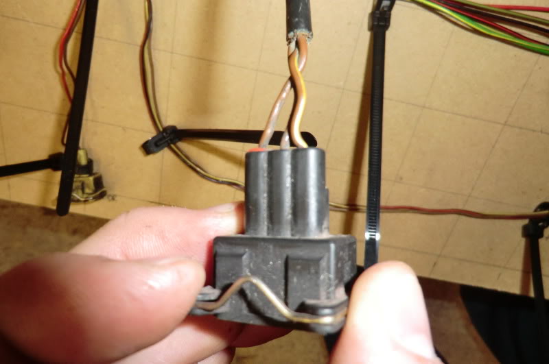
Hopw this helps
Ginger
.
Right, on the plug if you looking into the terminals so the wires are going away from you there numbered left to right 1,2,3
1=brown
2=brown green
3=brown yellow
Hopw this helps
Ginger
.

Virgin
Joined: Feb 2010
Posts: 7
Likes: 0
From: the Balkans
Hi,
on my N7BA, 96kW, 1998cc, 2005 Ford Mondeo TDCi engine, there is a MAP sensor with 4 wire connector. Is anyone able to post its wiring diagram?
1C1A-9F479-AA This should be the Ford spare part number.
Is a DC voltage the sensor's output signal or is it a square wave periodic signal which changes its frequency depending on the pressure?
Can anyone let me know the signal range according to the pressure in the intake manifold?
I measured the values below
1) GND
2) Power 5VDC
3) Vref 5VDC
4) Some 4.85VDC voltage - This voltage never changes even though I change the pressure in the intake manifold.
I got these values using a multimeter, but
when I use an oscilloscope the 4) reads 3.85VDC with a lot of negative sparks on the signal when the engine is running. Pressing the acceleration pedal increases the noise on that signal. I wonder if the 1V difference is for the much lover input impedance of the scope comparing to a multimeter. No probes used just a banana plug to banana plug test leads and 1V per division on the scope. Scope was analogue. Could it be the internal impedance of the sensor changed to a high value?
The sensor is located on the intercooler output pipe just before the intercooler hose that goes to the EGR valve.
Do you consider this MAP sensor as a faulty one?
ECM doesn't trow any pending code out to my Ford Super II Scanner regarding the MAP sensor.
Thanks
Last edited by e2e4; Apr 17, 2017 at 05:08 PM.
C**t


Joined: Oct 2003
Posts: 7,997
Likes: 269
From: Norn Iron
At 2005 it is unlikely to be a digital sensor.
Often 4 wire sensors can be pressure and temperature combined.
And are you not getting readings when viewing live data, or why are you investigating this ?
Often 4 wire sensors can be pressure and temperature combined.
And are you not getting readings when viewing live data, or why are you investigating this ?
Virgin
Joined: Feb 2010
Posts: 7
Likes: 0
From: the Balkans
Hi stevieturbo, thanks for your reply,
in the mean time, I've checked, a DC voltage is the sensor's output so, you were right. A guy from a scrap yard had sold me a 1C1A-9F479-AA used sensor and it gives approximately 1.6 to 4.4VDC when its piezoelectric sensing bridge is exposed to an absolute pressure of 1 to 2 bar, respectively. So, the sensor in the vehicle in question is fired. Also, I've found 1C1A-9F479-AA isn't the right spare part for this vehicle; at length I took the fired sensor off the vehicle and saw its part number was 4S7Q-9F479-AA. I've ordered a brand new one and it's on its way to my place but it will take some 10 days to arrive.
In my humble opinion, the engine went into the limp mode. That was the reason to investigate. There is no pressure in the intake manifold. The rotary electronic actuator may be at fault too since there are two pending codes shown on my F Super 2 scanner. Those are P132A and P132B. According to info I found, it's all about the electronic actuator which manages the turbine's vanes. So, the ECM was getting wrong signals from at least two electronic devices.
I can't know if the two mentioned sensors have the same or different transfer characteristics, until I get both of them in front of me and test.
I also don't know the part number for the stepper motor in the actuator. I won't take the actuator apart until I see how the engine works with the genuine MAP sensor.

Thread
Thread Starter
Forum
Replies
Last Post
DixieTheKid
Ford Sierra/Sapphire/RS500 Cosworth
11
Jun 6, 2020 11:20 AM
wheelwizardrefurbs
Technical help Q & A
24
Sep 24, 2015 08:35 PM
wheelwizardrefurbs
Technical help Q & A
8
Sep 18, 2015 08:59 PM