.
Hiya mate, I've got my L6 2wd engine loom on a board (see below) this is correct as per my loom
pin 11=Brown/Green
Pin 15-Brown
pin 30=Brown/Yellow(but T's to a Red @ the ECU plug)
pin 19=earth braiding that is around the other 3 wires
The braid is to reduce noise/interference.
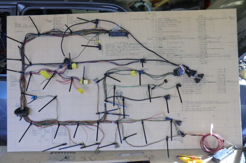
(pins 11, 15 & 19 have 2 wires at the ECU plug)
If you save the pic then open it from your on picture file you'll be able to zoom in to it. Where your diagram shows joins to other sensors, they are actually at the ECU plug it's self (2 wires in 1 terminal) And the oval ring just under the MAP is the braided earth.
Hope this helps mate, if you need a better pic of the loom board give me shout as 1 part is covered by the AMP plugs
Ginger
.
(Edited for more info)