
Connecting pectel t6


Thread Starter
Too many posts.. I need a life!!
Joined: May 2004
Posts: 577
Likes: 1
Hi
Im trying to figure out what goes where on my wiring and so far im stuck with the following questions:
The engine has a pectel t6 ecu with wiring that is off a other car than the one its currently fitted to.
1: Tacho output, is this a pin i have to configure under ECU hardware setup => multi function output channels? i would believe that this was a static pin, but looks to me that it has to be configured in software to one of the 6pwm channels?
Which is strange, as none of the pwm channels is connfigured with tacho_Drive and i would assume that the previous owner had a tachometer?
2. 5v sensor supply (ecu pin 22) this is a output pin right?
so if i power on the ecu i will see 5volts all the time here?
3. On my ecu pin 21 is configured as water_injection.
Will i see 12volts on this pin when waterinjection tresholds are met?
In other words is it this pin i should connect to my water injection pump relay?
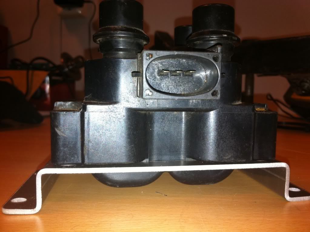
4. On the coilpack i have 3pins
Left = ?
midle = ground
Right = 12volt
I assume that the left pin gets signals from the ecu to trigger a spark?
More questions will probably appear as i start connecting this
Im trying to figure out what goes where on my wiring and so far im stuck with the following questions:
The engine has a pectel t6 ecu with wiring that is off a other car than the one its currently fitted to.
1: Tacho output, is this a pin i have to configure under ECU hardware setup => multi function output channels? i would believe that this was a static pin, but looks to me that it has to be configured in software to one of the 6pwm channels?
Which is strange, as none of the pwm channels is connfigured with tacho_Drive and i would assume that the previous owner had a tachometer?
2. 5v sensor supply (ecu pin 22) this is a output pin right?
so if i power on the ecu i will see 5volts all the time here?
3. On my ecu pin 21 is configured as water_injection.
Will i see 12volts on this pin when waterinjection tresholds are met?
In other words is it this pin i should connect to my water injection pump relay?
4. On the coilpack i have 3pins
Left = ?
midle = ground
Right = 12volt
I assume that the left pin gets signals from the ecu to trigger a spark?
More questions will probably appear as i start connecting this
Thread Starter
Too many posts.. I need a life!!
Joined: May 2004
Posts: 577
Likes: 1
One additional question.
I need to make the rs232 to jack cable.
I found this pinout image:
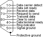
Is it correct that i should connect rs232 pin 2 to ecu pin 10 RS232TX
rs232 pin 3 to ECU pin 29 rs232RX
and rs232 pin 5 to ECU pin 46 commsgnd?
I need to make the rs232 to jack cable.
I found this pinout image:
Is it correct that i should connect rs232 pin 2 to ecu pin 10 RS232TX
rs232 pin 3 to ECU pin 29 rs232RX
and rs232 pin 5 to ECU pin 46 commsgnd?

I've found that life I needed.. It's HERE!!
Joined: Jan 2008
Posts: 1,134
Likes: 25
From: Netherlands
1. Have to lookup that one. I don't think I used a PWM channel for the tacho.
2. Yes, you will see 5 volt here. Needed for the map-sensor and the throttle position sensor.
3. As fas as I remember this is switched to ground not 12 volt.
4. What kind of coil pack do you have? Ford wasted spark?
5. Comms should work with 3 wires. In the worst case you have to switch pin 2 and 3 in the connector.

Wahay!! I've lost my Virginity!!
Joined: Jul 2010
Posts: 73
Likes: 0
From: Geneva, Switzerland
RS232 COMS: TX(ECU10) to TIP, RX(ECU29) to RING, DIGGND(ECU46) to SLEEVE on female 6.35mm jack is the std Pectel wiring.
COIL: Center is +12V, left is Coil A (cyl 1 & 4) and goes to IGN1(ECU19) and right is Coil B (cyl 2 and 3) and goes to IGN2(ECU55). Set firing sequence (ignition channel mapping under ignition coil config in the hardware menu) to 1:SPARK_1, 2:WASTE_2, 3:WASTE_1, 4:SPARK_2 and coil mode to Normal.
Connect +12V to the WI relay's coil, and the ground side of the relay's coil to PWM6(ECU21). NB: PWM5(ECU45) and PWM6(ECU21) are low current, OK for relay or tacho drive or a gear shift LED. All PWM output are ground side.
I've found that life I needed.. It's HERE!!
Joined: Jan 2008
Posts: 1,134
Likes: 25
From: Netherlands
Coil question: see previous answer.
Tacho: configure under ECU hardware setup => multi function output channels, I used PWM 5 (pin 45). Also configure in Ecu Software setup => output channels => Tacho output. This setting depends on you actual instrument: normally 2 pulses for a 4-cyl tacho.
If the tacho has no signal then connect a 2k2 resistor between tacho signal wire and 12 volt.
Thread Starter
Too many posts.. I need a life!!
Joined: May 2004
Posts: 577
Likes: 1
Thanks guys, it starting to make sense now.
Regarding the coil.
I previously stated:
Left = ?
midle = ground
Right = 12volt
This because i had a pin on the inboard 37pin multiplug on the engineloom that went to the right side of the coil, but now i also see that ECU19 goes to this pin as well.
So this means that this pin is intended to connect the tachometer right?
I can use signals from the right side of the coil for this?
Any reason why they get the tacho readings directly from the coil instead of a separate tachodrive output channel?
So how it really is is like this:
Left = ECU55
midle = 12volts
Right = ECU19 + pin39 on multiplug for tacho reading
Last edited by Mark_1; Jul 19, 2011 at 09:13 AM.
Trending Topics
I've found that life I needed.. It's HERE!!
Joined: Jan 2008
Posts: 1,134
Likes: 25
From: Netherlands
You could use either side (Left or Right) as a Tacho signal.
BUT (big BUT) then the tacho must be setup for 2 cylinders as the sides are only triggered once per rev.
Why? We always used to do it like that (with single coil)? Or because that way you don't need a resistor to 12 volt? Or didn't know the T6 has a tacho output?
Or because they used something else than a T6. You say 37-pin multiplug. Is that the ecu connector? Because a T6 has more pins.
Thread Starter
Too many posts.. I need a life!!
Joined: May 2004
Posts: 577
Likes: 1
My engine loom has the big 55pin connector, the connectors for the enginecompartment and a 37pin multiplug intended to quickly connect all the internal cockpit wires such as 12volt, als, comms, tripmeter, starter and so on to the loom.
Thread Starter
Too many posts.. I need a life!!
Joined: May 2004
Posts: 577
Likes: 1
I had connected one of the rs232 connectors wrong, im now able to communicate with the ecu 
So far everything looks good, so thanks guys for your help, it really helped me out.
So far everything looks good, so thanks guys for your help, it really helped me out.

Thread
Thread Starter
Forum
Replies
Last Post
Mark RS
Ford RS Cosworth Parts for Sale
7
Oct 12, 2015 06:01 AM