
muppet needs help please.......


Thread Starter
15000
Joined: Jul 2010
Posts: 32
Likes: 0
From: manchester
Hi guys and gals.
can anybody help me im doing a countach replica with a sierra column round hazard one.Im in need of wiring diagrams for it or anybody near lees oldham fancy a chat and a brew and i can pick ya brains cheers in advance whitty.
can anybody help me im doing a countach replica with a sierra column round hazard one.Im in need of wiring diagrams for it or anybody near lees oldham fancy a chat and a brew and i can pick ya brains cheers in advance whitty.


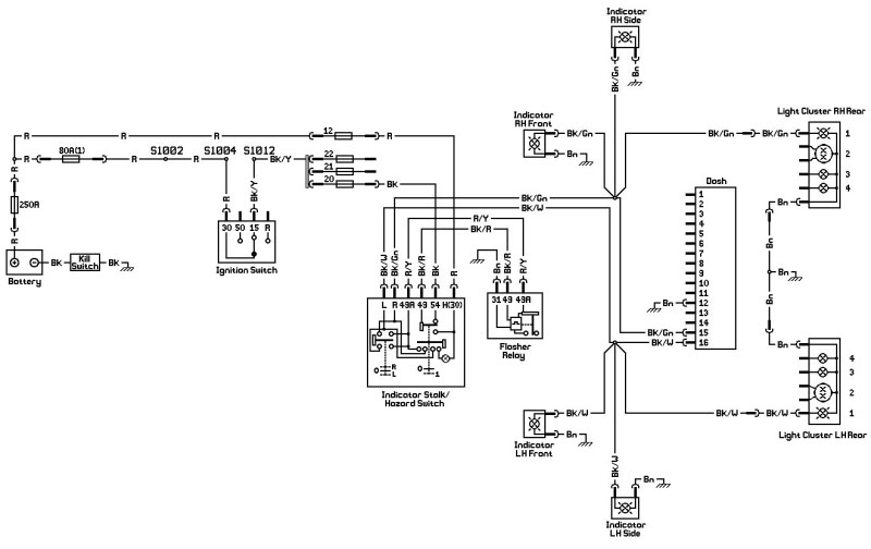
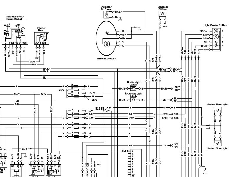
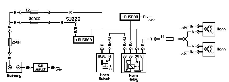
as per the right hand side area of the "indicator stalk/hazard switch" in the drawing above - the flasher unit wires are to terminals 49 and 49A
or do you mean you want a part number for the flasher unit itself ?
or do you mean you want a part number for the flasher unit itself ?
Thread Starter
15000
Joined: Jul 2010
Posts: 32
Likes: 0
From: manchester
Hi jon.
have you by any chance got diagrams for lights and wiper would be a fantastic help and if you are ever in manchester you would be more than welcome to come and have a drive of the cars thanks again lee.
have you by any chance got diagrams for lights and wiper would be a fantastic help and if you are ever in manchester you would be more than welcome to come and have a drive of the cars thanks again lee.
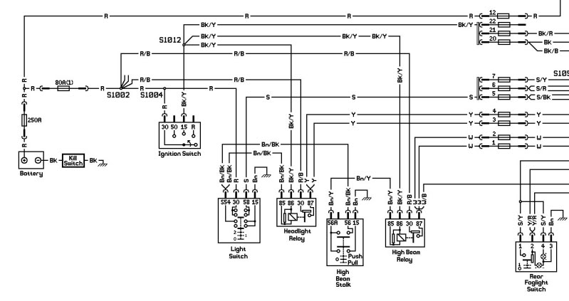
The diagram above and the other diagrams I've got for the lights and wipers are specific to my Sapphire with regards power supply and fuses - in the above diagram, there isn't a kill switch, 250A fuse or 80A fuse as standard and it just so happens that I'm using fuses 12 and 20 to supply the stalk, and in the lighting diagram, I've rewired the front lights with individual relays for each headlight and high beam.
If you're using a sierra fuse box, you may be better off using a Haynes manual wiring diagram. If you only want them for circuit layout, then they'll be OK....
If you're using a sierra fuse box, you may be better off using a Haynes manual wiring diagram. If you only want them for circuit layout, then they'll be OK....
Trending Topics
Thread Starter
15000
Joined: Jul 2010
Posts: 32
Likes: 0
From: manchester
jon you are a jem many thanks for them. Just need to sort the horn now 2 wires from horn push brown i think.Im using a loom for this car and it has 2 wires from 2 fuses one to horn push and one to horn......lee
That reminds me - there are 2 different side/headlight stalks - one with an earth tag (1/4 inch push-on) and one without. IIRC, this tag is only for the windscreen washer pump. I don't know why, but on the one with the tag, the washer pump is fed 12V by the stalk (black wire I think) and then instead of running a wire from the washer pump straight to earth, the wire returns to the stalk (black/blue) and then to earth via the tag (brown wire)(brown is always an earth on all circuits). It's easy enough to rewire the washer pump so it doesn't return back to the stalk.
With regards the horn, as standard 12V is fed through the coil side of a relay and then to the column, so the horn push brown needs to be earthed.
With regards the horn, as standard 12V is fed through the coil side of a relay and then to the column, so the horn push brown needs to be earthed.
Thread Starter
15000
Joined: Jul 2010
Posts: 32
Likes: 0
From: manchester
Thanks jon.
i have ran into a problem... i have a wire from fuse box that states it goes to 49a does this now go to h30 and 54 keys into 15 on the ign switch.Are the numbers what fuses they went to on the orig loom.
i have ran into a problem... i have a wire from fuse box that states it goes to 49a does this now go to h30 and 54 keys into 15 on the ign switch.Are the numbers what fuses they went to on the orig loom.
What do you mean by "i have a wire from fuse box that states it goes to 49a"? What "states" where the wire comes from/goes to? In the Haynes manual and the diagram above, the wire from stalk terminal 49A goes to the flasher relay terminal 49A. Are you sure your wire goes to the fuse box? What colour is the wire?
As I said above, the diagrams are based on my car. If you're using a sierra loom, let me know and I'll tell you what the standard fuse numbers are.
As I said above, the diagrams are based on my car. If you're using a sierra loom, let me know and I'll tell you what the standard fuse numbers are.
Thread Starter
15000
Joined: Jul 2010
Posts: 32
Likes: 0
From: manchester
Hi jon.
sorry the problem i have is the countach replica came with wiring loom but the column was from something else,i am trying to use a sierra column and trying to work out how from the kit loom to connect to sierra column. With your diagrams i have rewired the column but i then have a few wires from the loom 1 says to 49a on hazard switch and i have a park for wiper and a feed for wiper does the column power the relays....
im sorry it so hard to try and work out im going to try wiring hazards first but need to work out were 54 goes to on the diagram it states numbers. Are they fuses or can i wire straight to 15 on ign switch. if you would help me out on this few probs i will of course make it worth your time thanks again for all the help lee.
Perhaps the flasher relay is in the fuse box you've got (they are behind the dash in sierras), in whuch case there shoulkd also be another wire to it (from stalk terminal 49).
The loom diagrams are all completely self contained - they show where the circuits get their powerwhether a permanent feed or switched through the ignition, and there are no "Soldered Joint No. 123456 from Diagram XYZ on page 345". The wiper circuit as show includes the parking (as long as it's a sierra wiper motor and you connect it up as shown), and there are no further components needed to make the wipers work other than those shown.
I hope you've gathered by now that the terminal numbers as they are shown in the diagrams are exactly as they appear on, for example, the stalks themselves.
54 = ignition switched stalk feed for the indicators
H(30) = permanent feed for hazards (so they work with the ignition off)
Thread Starter
15000
Joined: Jul 2010
Posts: 32
Likes: 0
From: manchester
jon what a jem.............
I am nearly all done just need to know how i wire the capri twin lights in now and i have only 2 relays dim. main. yellow relays any idea if i would need 4 to run the capri lights. hope you can pull me out on this one
I am nearly all done just need to know how i wire the capri twin lights in now and i have only 2 relays dim. main. yellow relays any idea if i would need 4 to run the capri lights. hope you can pull me out on this one
Thread Starter
15000
Joined: Jul 2010
Posts: 32
Likes: 0
From: manchester
jon your a real star...................
last one i hope...
Right on the back of the headlights on number 1 there is only 1 bulb with 1 connection on light 2 there is 2 one in the center and 1 below.
how do i wire these and how do they earth?
I know it sounds daft but i do not want to wire them arse about face.
last one i hope...
Right on the back of the headlights on number 1 there is only 1 bulb with 1 connection on light 2 there is 2 one in the center and 1 below.
how do i wire these and how do they earth?
I know it sounds daft but i do not want to wire them arse about face.
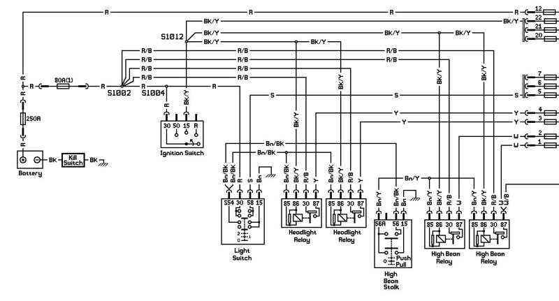
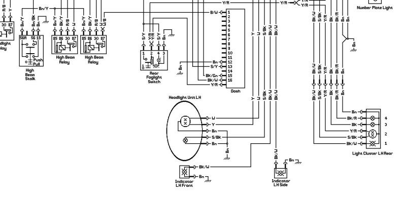
the light with 2 bulbs (outer unit) is for headlight and side light
the light with 1 bulb (inner unit) is for high beam
Wire them up with the yellow(headlights), white(high beam) and slate/black or slate/red (sidelights) wires and run individual brown wires from each bulb to a common earth point each side of the car
the light with 1 bulb (inner unit) is for high beam
Wire them up with the yellow(headlights), white(high beam) and slate/black or slate/red (sidelights) wires and run individual brown wires from each bulb to a common earth point each side of the car

when you say the hazards work, do you mean the light on the top of the stalk works, or the lights at the corners of the car ?
what happens when you indicate right ? any noise from the flasher relay, or silence ?
double check the terminals on the back of the stalk - check that the numbers on the stalk correspond to the numbers in the above diagrams
what happens when you indicate right ? any noise from the flasher relay, or silence ?
double check the terminals on the back of the stalk - check that the numbers on the stalk correspond to the numbers in the above diagrams
Thread Starter
15000
Joined: Jul 2010
Posts: 32
Likes: 0
From: manchester
Thanks jon.
all lights work now and flashers both at the light and four corners left ind works but the right has no power there is a brown and white wire that says it goes to relay but if i put it on 85 when ign on right light works
how can i have hazards and left ind but no power to right is the brown and white wire the cause sorry lee.
When the hazards are turned on there is an internal connection in the stalk (see the switch representation in the diagram above) between the output from the flasher relay (stalk terminal 49A) and both the left ("L") and right ("R") indicator outputs, so the fact that the right indicators work when the hazards are turned on is OK.
If you unplug the stalk and switch the right indicators on, have you got continuity between stalk terminals "R" and "49A" ? You should have with the indicator on. If not, suspect a dodgy connection inside the stalk. (I think you'll find it's OK - see thoughts below).
Re: the brown/white wire - when you say the right indicator works if you put it on "85", do you mean if you put 12V onto the wire, then the indicators work (flash) correctly ? Is the wire to/from a relay in the fuse box ?
I'm wondering if this wire is an original power feed wire to the original flasher relay in the fuse box (equivalent to the wire between terminals "49" in my diagram above), but you've added your own flasher relay outside the fuse box, so what you've done is route the right indicator output wire from stalk terminal "R" to the original flasher relay in the fuse box instead of directly to the indicators. However, as the original flasher relay doesn't any longer have a power supply after you've re-worked your loom, then the flasher relay doesn't work, resulting in no right indicators (unless of course you do provide power to the superfluous flasher relay via the brown/white wire). (see representation below for how I think your wiring currently is)
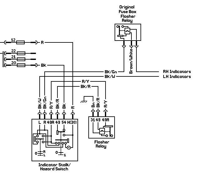
Where does your wire from stalk terminal "R" go to ? I bet it doesn't feed the right indicators directly as it should, but runs to the fuse box. You should have continuity between stalk terminal "R" and one of the wires at the bulb holder for any of the right hand side indicstors.
If you unplug the stalk and switch the right indicators on, have you got continuity between stalk terminals "R" and "49A" ? You should have with the indicator on. If not, suspect a dodgy connection inside the stalk. (I think you'll find it's OK - see thoughts below).
Re: the brown/white wire - when you say the right indicator works if you put it on "85", do you mean if you put 12V onto the wire, then the indicators work (flash) correctly ? Is the wire to/from a relay in the fuse box ?
I'm wondering if this wire is an original power feed wire to the original flasher relay in the fuse box (equivalent to the wire between terminals "49" in my diagram above), but you've added your own flasher relay outside the fuse box, so what you've done is route the right indicator output wire from stalk terminal "R" to the original flasher relay in the fuse box instead of directly to the indicators. However, as the original flasher relay doesn't any longer have a power supply after you've re-worked your loom, then the flasher relay doesn't work, resulting in no right indicators (unless of course you do provide power to the superfluous flasher relay via the brown/white wire). (see representation below for how I think your wiring currently is)
Where does your wire from stalk terminal "R" go to ? I bet it doesn't feed the right indicators directly as it should, but runs to the fuse box. You should have continuity between stalk terminal "R" and one of the wires at the bulb holder for any of the right hand side indicstors.
Last edited by jon@work; Jul 17, 2010 at 02:33 AM.
Thread Starter
15000
Joined: Jul 2010
Posts: 32
Likes: 0
From: manchester
Hi jon.
it is all wired up as your diagrams but no power to black and green right side ind i have put another switch on but exactly the same happens although i do not know if that switch works ither do you think it could be the switch?
it is all wired up as your diagrams but no power to black and green right side ind i have put another switch on but exactly the same happens although i do not know if that switch works ither do you think it could be the switch?
Thread Starter
15000
Joined: Jul 2010
Posts: 32
Likes: 0
From: manchester
Yipe...........................
forget that jon.
my folt there is 2 black and white wires from ind stalk one to 49a and one to left ind. I had them arse about face just 2 more to do horn and washer
any idea on wiring air horns to column i have a relay in the kit but there is a posotive from the horn and a return (if that makes sence)
is your horn operated from the end of the stalk or the centre of the steering wheel ?
I've got my horns, operated on the end of the stalk, as below:
this is nothing like standard sierra horn wiring, but is simple and it works
and the windscreen washer :
again, this is not standard - remember I mentioned above about stalks with a seperate earth tag (1/4" push-on terminal) - but this seems simpler to me and easier to fault trace if necessary
Thread Starter
15000
Joined: Jul 2010
Posts: 32
Likes: 0
From: manchester
Hi jon
a couple of questions for you
1. can i wire the back lights to headlight relay (i have no back lights and with using the new column the wire that went to the headlights it is not used)
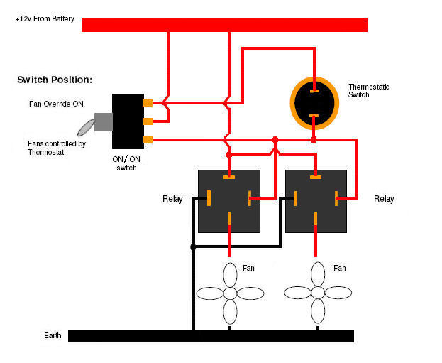
2. wiring 2 rad fans with overide switch.
cheers again lee
a couple of questions for you
1. can i wire the back lights to headlight relay (i have no back lights and with using the new column the wire that went to the headlights it is not used)
2. wiring 2 rad fans with overide switch.
cheers again lee
1. you could use the headlight relay (but then they won't work when you turn on your sidelights unless you mean the sidelight relay) but why not use the output from the stalk (terminal 58) ?
2.
2.
Last edited by jon@work; Jul 19, 2010 at 12:38 AM.
Thread Starter
15000
Joined: Jul 2010
Posts: 32
Likes: 0
From: manchester
Once again jon you amaze me...........
can the fans use only one relay?
the less wires in the front the better.
and can you give me the numbers on the relays.
I am nearly all there now just need to sort out how i get power to brake switch and of course i need to sort out whot ford wiper unit they use on these countach replicas im wondering if i can use a back wiper...........
any ideas would not go a miss.
What are the fans off ? If they're sierra ones, they're quite current hungry as they get older. One relay may be OK, but two would be better.
Can you get in touch with the kit manufacturer to find out what wiper motor to use, or is there a dedicated kit car forum you could ask on ?
Can you get in touch with the kit manufacturer to find out what wiper motor to use, or is there a dedicated kit car forum you could ask on ?
Last edited by jon@work; Jul 19, 2010 at 10:16 AM.
Thread Starter
15000
Joined: Jul 2010
Posts: 32
Likes: 0
From: manchester
Thanks jon.
I will use 2 relays and put them under the dash.
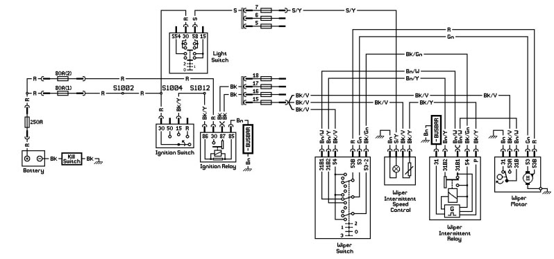
i have found out they use mk5 escort rear wiper so i went and got one but i need to know were i get the park from. I have it wired up but cant find were the park goes on the switch or relay. Hope that makes sence.
I will use 2 relays and put them under the dash.
i have found out they use mk5 escort rear wiper so i went and got one but i need to know were i get the park from. I have it wired up but cant find were the park goes on the switch or relay. Hope that makes sence.
I hope you got the connector with the motor, and some of the wiring.
If you've got a car battery handy, then if the motor is the same as a sierra rear wiper motor (which it probably is) try the following :
1. connect the brown wire to earth
2. connect the black/purple wire (wiper motor terminal number 53A) to +12V to replicate the ignition-switched feed to the motor
3. connect the black wire (wiper motor terminal number 53) to +12V to replicate the column stalk, so just for a few seconds.
This should get the motor going, and if so it should self park a few seconds after you've removed the black from the positive battery terminal. (From the Haynes manual, it looks like the self park is self contained within the motor.)
If the above works, then you (ie me) can have a think about connecting it up to your stalk.
Are you sure it's a rear wiper motor you need, as this'll only give you single speed wipers ?
Thread Starter
15000
Joined: Jul 2010
Posts: 32
Likes: 0
From: manchester
yep it works...
53a goes to ign switch.
Right thought i had all the wiring nearly done but forgot a few thing....
wiring dash.
can i run through them 1by1
oil first 2 terminals on gauge one goes to oil sender (is the other earth)
do i run a warning light of this.
2.tach (rev counter) 2 terminals and 1 earth to gauge body.
3.water 2 terminals one to water sender is the other earth
4.amps there is a + and - were do they go
5 fuel 2 terminals 1 goes to fuel tank i guess were does the other go.
6.clock were can i get power from for this can i pinch from acc yellow on column?
then im up to front spots and rear fogs. I think you have wired all the sodding car im ill with it but im also chuffed to bits its all comming together.Jon i will indead sort you some payment out for all your time and brain picking you are a real gent THANK YOU................
Let me have a think about how to wire up the wipers to your stalk and I'll get back to you.
If you feel so inclined, make a donation to a local animal charity of your choice, and don't forget to help out someone else in need if you can.
Right thought i had all the wiring nearly done but forgot a few thing....
wiring dash.
can i run through them 1by1
1. oil first 2 terminals on gauge one goes to oil sender (is the other earth)
What make is the gauge, and what colour is the wire ? I'd expect it to connect to +12V, and earth through the body of the sender.
do i run a warning light of this.
You really should run a warning light. How you go about it depends on the location of the sender for the pressure gauge - ie has the gauge sender replaced the standard switch ? If so, you'll need to get an adaptor so you can run both the pressure gauge sender and a low pressure warning light switch. What engine is it ? Where is the sender for the pressure gauge located ?
2. tach (rev counter) 2 terminals and 1 earth to gauge body.
One wire will be +12V, and the other will connect the the ignition coil negative.
3. water 2 terminals one to water sender is the other earth
As per the oil pressure, I'd expect it to go to +12V not earth
4. amps there is a + and - were do they go
You'll have to investigate your particular gauge on google. May need a shunt (resistor), which you have or haven't got.
5 fuel 2 terminals 1 goes to fuel tank i guess were does the other go.
As per the other gauges, I say +12V
6.clock were can i get power from for this can i pinch from acc yellow on column?
Yes if you want the clock to stop when you turn off the ignition. I'd suggest perhaps tapping into the fag lighter wiring, if you've got one. Double check that it is permanently live.
then im up to front spots and rear fogs.
Wire the front spots up so they come on with the high beam. Use the feed to the high beam relay to also feed another relay for the spots.
The rear fogs should only come on when the headlights are on. You'll need to wire up a switch that has a feed from the headlight feed terminal on the stalk. What switch are you using ?
Thread Starter
15000
Joined: Jul 2010
Posts: 32
Likes: 0
From: manchester
Fantastic thanks jon.
and i will make a very nice donation to R.S.P.C.A
I have a long shot for you test you out ha ha.
any idea on how to wire headlight motor so they go up and down relays and to stalk..................
and i will make a very nice donation to R.S.P.C.A
I have a long shot for you test you out ha ha.
any idea on how to wire headlight motor so they go up and down relays and to stalk..................
Re the wipers, I'm going to start a new thread to find out what stalk movements there are (I think it'll be 2 positions - one to get the rear wiper to work, and a second for the rear wash), and if the rear wiper is intermittent or on constantly. Once I know this, I'll be able to come up with a wiring diagram for you.
Question for you : Does your headlight/wiper stalk have the seperate 1/4" push-on earth tag ?
OK back to the wipers
Below is the sierra rear wiper circuit diagram in the Haynes manual :
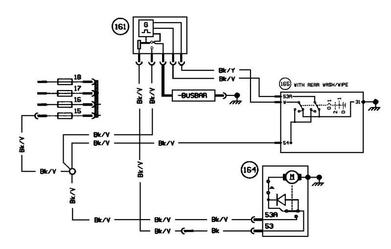
165 is the stalk, showing only those terminals that are used for the rear wiper and rear washer
161 (IMPORTANT) is the rear wiper intermittent relay
164 is the rear wiper
I've removed the ignition switch, ignition relay, etc to simplify. All power comes from fuse 15, which is energised with the ignition on.
With the ignition on and the rear wiper turned on to position 1 (intermittent), +12V from stalk terminal 54 is fed to stalk terminal 53A and then onto the intermittent relay. This in turn, using magic, sends an intermittent pulse to the rear wiper motor, which also has a constant +12V feed straight from the fuse to motor terminal 53A.
To get your wipers working intermittently, you will need to get a sierra rear wiper intermittent relay, not a front intermittent relay. This is because the self-parking works differently between the front and rear wiper motors.
Ignore what happens when the rear wiper switch is in position 2.
If constant +12V is fed to wiper motor terminal 53, the wiper operates continuously, as you determined yesterday in the quick lash-up you did with the battery and a few wires to the motor connector. Double check this, please, and confirm that this is correct.
So what you need to do now is change the circuit so that it operates when you move the motor to the front of your car, and works with the "Front Wiper" stalk controls. See diagram below :
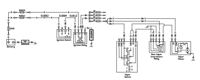
The front wiper stalk (one down for intermittent, 2 up for twin speed wipers) now works the rear wiper motor on the front of your car. However,
1. the intermittent wipe speed is no longer adjustable
2. the rear wiper motor only operates continuously at a single speed - positions 1 & 2 of the stalk have been bridged, so the wipers will work with the stalk in either position, but only at the same speed.
I suggest after you've got a rear wiper intermittent relay that you again do a temporary lash-up to check it all works as I hope it should. You may need to add a couple of diodes and another relay, but we'll cross that bridge if we come to it.
Below is the sierra rear wiper circuit diagram in the Haynes manual :
165 is the stalk, showing only those terminals that are used for the rear wiper and rear washer
161 (IMPORTANT) is the rear wiper intermittent relay
164 is the rear wiper
I've removed the ignition switch, ignition relay, etc to simplify. All power comes from fuse 15, which is energised with the ignition on.
With the ignition on and the rear wiper turned on to position 1 (intermittent), +12V from stalk terminal 54 is fed to stalk terminal 53A and then onto the intermittent relay. This in turn, using magic, sends an intermittent pulse to the rear wiper motor, which also has a constant +12V feed straight from the fuse to motor terminal 53A.
To get your wipers working intermittently, you will need to get a sierra rear wiper intermittent relay, not a front intermittent relay. This is because the self-parking works differently between the front and rear wiper motors.
Ignore what happens when the rear wiper switch is in position 2.
If constant +12V is fed to wiper motor terminal 53, the wiper operates continuously, as you determined yesterday in the quick lash-up you did with the battery and a few wires to the motor connector. Double check this, please, and confirm that this is correct.
So what you need to do now is change the circuit so that it operates when you move the motor to the front of your car, and works with the "Front Wiper" stalk controls. See diagram below :
The front wiper stalk (one down for intermittent, 2 up for twin speed wipers) now works the rear wiper motor on the front of your car. However,
1. the intermittent wipe speed is no longer adjustable
2. the rear wiper motor only operates continuously at a single speed - positions 1 & 2 of the stalk have been bridged, so the wipers will work with the stalk in either position, but only at the same speed.
I suggest after you've got a rear wiper intermittent relay that you again do a temporary lash-up to check it all works as I hope it should. You may need to add a couple of diodes and another relay, but we'll cross that bridge if we come to it.
Last edited by jon@work; Jul 20, 2010 at 03:26 PM.
Thread Starter
15000
Joined: Jul 2010
Posts: 32
Likes: 0
From: manchester
Hi jon.
Wow you realy are fantastic.
had another good day today. Rear fogs work now and front spots come on with main (looking good) wired up the dash lamps and found the wire from the fuse box that powers the gauges so things are nearly there. just the fans to do but i have from fuse 18 on panel a wire + to fan and a wire + to switch wich is on the rad itself can i wire these to an overide switch as it looks like it has a relay for the fan built in. cheers again...