
Fan Prob on Saff Cossie


Thread Starter
Wahay!! I've lost my Virginity!!
Joined: Feb 2006
Posts: 67
Likes: 0
From: North London
Hi all, as usual us cossie owners can�t take the car out without having a problem. Mine now is the dreaded fan problem, Ive taken the Cossie out now visiting the Inlaws house, and when i was pulling up the temp seemed too high, so I managed to pull the car on the drive and turn the car off.
I though ok, here we go again, i checked the fuse box to see a Blue 15amp fuse was fried. Number 8, on the left of the cluster of fuses, about 4 from bottom. So i replaced it and nothing happened, so i thought ok, i took the connector out to the fan switch and got one of the misses hair clips. I put the clip into the connector to see if the fans kick in and i keep blowing the fuse. I done this twice and both occasions the fuse fried.
But at the time when im putting the clip into the connector i can hear a relay ticking, its a yellow fuse next to the roman number 11 (XI).
Im wondering if there is another fuse casing the problem or is it somthing else.
Im just confused now why putting the clip in the connector aint kicking in the fan.
Ive checked it this was before to eliminate the fan switch problem
Any help greatly appreciated
Andy
The fuse should be 30A not 15A, even so ideally the fans need a rewire as the standard loom was sub standard to start with and many have melted. The fuel pump wiring drgrades as well and hence you end up with less power than you should at the pump which can lead to a melted engine. There are diagrams on here on how to do, very easy to DIY as well or you can buy pre made looms. You need sutiable grade wiring, SPST relay, Fuse and fuse holder (Fan Loom).
Martin
Martin
Thread Starter
Wahay!! I've lost my Virginity!!
Joined: Feb 2006
Posts: 67
Likes: 0
From: North London
Thanks Martin. I've always had it in my mind to change the wiring for the fan. I really dont like the wiring on it now. Not that it looks tacky or anything, just worry about it, cos it is a 22 year old car. I've had a look around but cant seem to find any posts Are the pre wired fan looms burtons sell any good.

20K+ Super Poster.
Joined: Jul 2006
Posts: 24,596
Likes: 4
From: uk
Very easy diy for under �10, or possibly a dead engine if not done, if everything is in order they can be totally reliable, esp considering the type and age of car, just taken my engine out with 200,000 miles on it, never broke down, just started drinking oil from shagged rings.
You ideally also need the fuel pump rewired, again very easy diy.
tabetha
You ideally also need the fuel pump rewired, again very easy diy.
tabetha
The rest of the wiring is ok, it's just due to the power draw on the mentioned circuits coupled with the fact they were sub standard to start with leave alone now and it spells trouble hence why it's good idea to rewire them. Can't comment personally on the Burtons ones but they are in general a reputable company. Theres someone on here called Ryan who sells looms as well.
Martin
Martin
Thread Starter
Wahay!! I've lost my Virginity!!
Joined: Feb 2006
Posts: 67
Likes: 0
From: North London
Hi guys, i took the fans out of the car, they are working all ok, I put them on a 12v battery and the span up ok. So as you guys have mentioned it looks as wiring problem, so im gonna change the wiring to the fan
Im just gonna have a search around to see if i can find any rewiring posts
Thanks Guys
Andy
Im just gonna have a search around to see if i can find any rewiring posts
Thanks Guys
Andy
Trending Topics

Thread Starter
Wahay!! I've lost my Virginity!!
Joined: Feb 2006
Posts: 67
Likes: 0
From: North London
Thanks Steve. I'll give it a go first  if all fails i'll get the loom seems something i can try. does anyone know where i can get a spst relay from. I can only find a spco relay from maplins.
The fan is normally a picture of like 4 blades never looked on mine TBH, I think Iceicle means A/C. SPST relay should be available from Maplins, or you could just use the original one seen as this won't be used after you rewire.
Martin
Martin

Thread Starter
Wahay!! I've lost my Virginity!!
Joined: Feb 2006
Posts: 67
Likes: 0
From: North London
Hi Guys. Im having so much trouble trying to get an spst relay. I've looked everywhere. Does anyone know where i can get one. I've tried Maplins. Places that sell relays to no avail.
20K+ Super Poster.
Joined: Jul 2006
Posts: 24,596
Likes: 4
From: uk
RS ANDY,
Pm me your addy and I'll pop one in the post to you, �1 ok ?, it may just not be called a SPST, single pole single throw, the most common ones, just look for the numbers 30, 85, 86, 87,, if it has a extra 87a don't worry can still be used, just look for these numbers on the terminal markings on them should be about �3, but if stuck pm me, I know halfords wilco car shops etc all sell them usually for fitting extra spot lights etc.
tabetha
You car is correct! I was doing something on mine and looked at the fuses at the same time and it is indeed 15A NOT 30A with the symbol being the icicle you said about as well, apologies re the fuse for some reason I thought it was 30A as this is what I used when I rewired. I would imagine yours is shorting somewhere.
Martin
Martin
Thread Starter
Wahay!! I've lost my Virginity!!
Joined: Feb 2006
Posts: 67
Likes: 0
From: North London
Hi All, can i ask for some help please, i managed to get the relay i needed. So as it was a nice day i thought id get the car fan done,
Im using the Diagram below, ive made the loom and quite proud of it cos it does look quite good, i know its a few wires, but still...
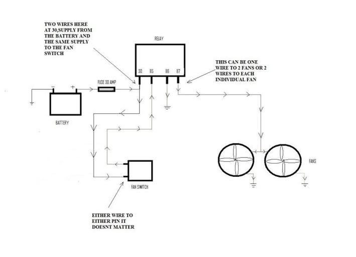
Im a little stuck wiring the fans, i understand that Relay Pin number 87 goes to the fans, and then the fans are earthed, But which wire below would i connect from pin relay 87. Would it be A or B.

Also when i disconnect the Wire to Loom and Wire to Fan from the black ford connecter will the connections at the Wire to loom still be live, and if so what i need to do to cut power to the Wire to Loom part.
I dont want this to stay live and short out and cause more grief.
Im hoping this makes sense,
I would like to thank in advance for any help.
Andy
Im using the Diagram below, ive made the loom and quite proud of it cos it does look quite good, i know its a few wires, but still...
Im a little stuck wiring the fans, i understand that Relay Pin number 87 goes to the fans, and then the fans are earthed, But which wire below would i connect from pin relay 87. Would it be A or B.
Also when i disconnect the Wire to Loom and Wire to Fan from the black ford connecter will the connections at the Wire to loom still be live, and if so what i need to do to cut power to the Wire to Loom part.
I dont want this to stay live and short out and cause more grief.
Im hoping this makes sense,
I would like to thank in advance for any help.
Andy
Generally speaking the earth wire for the fans will most likely be brown, so I would think those in the pic are the two lives (A) and (B) to the fans so both should connect to pin 87 but can't remember the colours of hand as it was a while since I done mine.
The only thing I would do different is your relay wiring you should have to lives going to relay and the earth should be switched by the relay as opposed to the live, this is as per the original design.
I.E have another live going to pin 85 and run the earth 86 to the fan switch and the other side of the switch to a good earth.
Martin
Thread Starter
Wahay!! I've lost my Virginity!!
Joined: Feb 2006
Posts: 67
Likes: 0
From: North London
Thanks for your reply martin, im just a tiny bit confused now, i would of thought either A or B would have been the live and the other A or B one would be earth. As the Wire to fan then splits up to the two fans.


As Jon says this is exactly as I describe the pic shows it better, this is the OE design.
Now you mention it I think you are right I had a better look at pic and I noticed the brown wire on the car loom side, brown is earth which tally's with the black on the fans which is earth. B and D would be ground and C and A are the lives.
Martin
Now you mention it I think you are right I had a better look at pic and I noticed the brown wire on the car loom side, brown is earth which tally's with the black on the fans which is earth. B and D would be ground and C and A are the lives.
Martin
Thread Starter
Wahay!! I've lost my Virginity!!
Joined: Feb 2006
Posts: 67
Likes: 0
From: North London
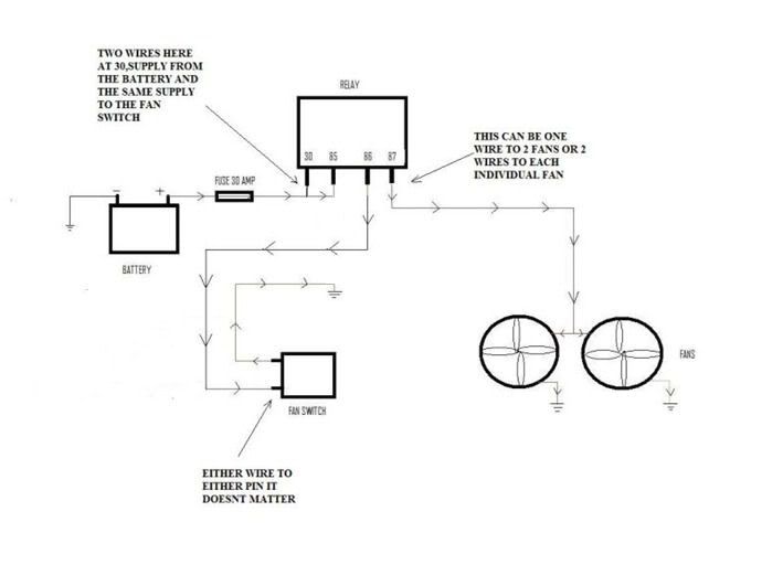
Thank you so much jon@work and martysmartie for the replies. So shall i use the second diagram now not the first one i posted, Just out of curiosity if the second one is the better one, why is it better?
Also the fan switch on the second diagram only has a single wire going to it, and then the fan switch is earthed, how does the realy know when to switch the fans on when the wire from the relay feeds power to the switch.
Many thanks once again
Also the fan switch on the second diagram only has a single wire going to it, and then the fan switch is earthed, how does the realy know when to switch the fans on when the wire from the relay feeds power to the switch.
Many thanks once again
You originally wired the live through the switch so it was switched live and you spured of pin 30 to the energised pin of the relay (85).
How it works in the second diagram 30 and 85 each have there own independant +12V feed. Since the relay is not grounded as it's wired through the switch the relay can not close hence no power to fans. When the switch closes this connects the earth from the relay to earth hence the relay trips. (Switched earth)
Martin
Thread Starter
Wahay!! I've lost my Virginity!!
Joined: Feb 2006
Posts: 67
Likes: 0
From: North London
Oh ok i get it , Sorry took a few times to get in sink into the head. Ill chage the wiring i made, not a hard thing, just have to remove a spade connector and connect it the other way Thank you martysmartie
Strictly speaking, the diagram I amended is still wrong. You should use have the 12V to terminal 86 and the feed to the switch from terminal 85, and be using a diode relay, rather than a resistor relay (for increased relay life).
Thread Starter
Wahay!! I've lost my Virginity!!
Joined: Feb 2006
Posts: 67
Likes: 0
From: North London
Hi All, i just wanted to send my thanks to everyone who helped. I�ve not had the chance to do the wiring fan till today as I�ve not been too well. As the sun was out i thought id get it done.
I�m so chuffed that i wired it all ok and it�s working brilliant. I had the car on and it was coming up to temp ok and fans were kicking ok. To me seems that the fans are working better, they seem a bit more powerful.
I�m just wondering now, in the pic of the wired connectors (post below 02-06-2010 09:49 PM) the wires to loom "C" and "D" is this still live and can i disconnect this so there is no power going to it.
Many thanks once again

That diagram above is good, it was done by a member on here only thing to make sure of is you use a good earth, so many people do an otherwise good job but use a rusty wheel well etc. Ideally you would earth on the battery itself.
Martin
Martin
I've found that life I needed.. It's HERE!!
Joined: May 2003
Posts: 1,115
Likes: 0
From: Out in the sticks
Running the earth back to the battery is unnecessary, provided you choose a suitable earth location near to the pump.
After you've made a new earth point, get out your multimeter and test the resistance between the pump-end of the new earth wire and somewhere else on the shell, and I'll bet the resistance is negligible (just the resistance of the meter leads). If it isn't, sand down the paint at the new earth point to improve the contact.
If you do decide for some reason that you need to run the earth back to the battery, then you are doubling the length of the circuit, and thus doubling the voltage drop in the wire, and must upgauge the wire accordingly - see the pic below (it's an Excel capture from a document I put together after being concerned by some of the wiring advice given on this site). The pic is for a circuit length of 8m (4m from battery '+' via a relay to the pump, 4m back to earth) and a maximum current of 18amps (which is the max current draw of a 044 pump).
I've found that life I needed.. It's HERE!!
Joined: May 2003
Posts: 1,115
Likes: 0
From: Out in the sticks
Running the earth back to the battery is unnecessary, provided you choose a suitable earth location near to the pump.
After you've made a new earth point, get out your multimeter and test the resistance between the pump-end of the new earth wire and somewhere else on the shell, and I'll bet the resistance is negligible (just the resistance of the meter leads). If it isn't, sand down the paint at the new earth point to improve the contact.
If you do decide for some reason that you need to run the earth back to the battery, then you are doubling the length of the circuit, and thus doubling the voltage drop in the wire, and must upgauge the wire accordingly - see the pic below (it's an Excel capture from a document I put together after being concerned by some of the wiring advice given on this site). The pic is for a circuit length of 8m (4m from battery '+' via a relay to the pump, 4m back to earth) and a maximum current of 18amps (which is the max current draw of a 044 pump).
surely even picking up chassis earth at the rear of the car close to the pump the distance traveled is still te same or is it because te route back is th hole car so bigger area which should mean less restance ?
i thinking of running a lengh of 16mm cable back there ?
if you can get it for the right price, then there is no downside to using wire of this size, provided you can get suitably sized terminals
I've found that life I needed.. It's HERE!!
Joined: May 2003
Posts: 1,115
Likes: 0
From: Out in the sticks
they make the cable for audio applications then use a distrubition block to gauge it down i was tinking of doing this for both the positive and the negative
Whilst on the subject, it is worth replacing, or at least testing the resistance of, the earth between the battery and the battery tray and bellhousing - these have been known to look OK but cause problems.