
Technical discussion on building a bottom end.


Thread Starter
Banned
Joined: Dec 2002
Posts: 142
Likes: 1
Building the bottom end of an engine
Right this is a fairly big one, so im going to deal with it in the following chapters which i will add as i get the chance (may change as i go along):
Basic engine assembly
Piston:
clearances
ring gaps
rods:
weighing
length checking
perhaps touch on mods like shot peening and desseming and mention steel rods
little and big end size and ovality
crank:
taper on big ends . mains
end float
checking throw per cylinder
journal size + regrinds
block:
line boring and why its needed
rebores and important issues concerning reboring (ie taper) / ovality
"decking" the block, and piston deck height
the use of piston squirters or spray bars
stress removal
girdles
Basic engine assembly
Big difference between properly building an engine and assembling one,
so I will cover the assembly of one first as thats the easy bit!
Fitting the crank to the block
On the crank there are journals that sit in the bearings (the jounal is the round shiney bit!)

In order to fit the crank into the block, you first remove the "mains caps" form the block
block with mains caps still installed:

Then to fit the crank you first place one half of the bearing shell into the block on each of the mains, then you lift the crank into place, and then you fit the other half the bearings to each of the caps, then refit the caps in place over the crank and torque down.
First half of the bearings installed in the block:

Crank installed in the block, and hte mains caps refitted:

After doing this the crank should spin freely by hand
(a small amount of oil should be used as an assembly lubricant, no precise amounts invovled just smear a little on the bearing face and the journals)
Fitting the pistons to the rods
The pistons are attached to the rods (via the little ends, so called simply cause they are smaller than the big ends!)
There is no bearing here as such, the pin that goes through is the bearing basically.
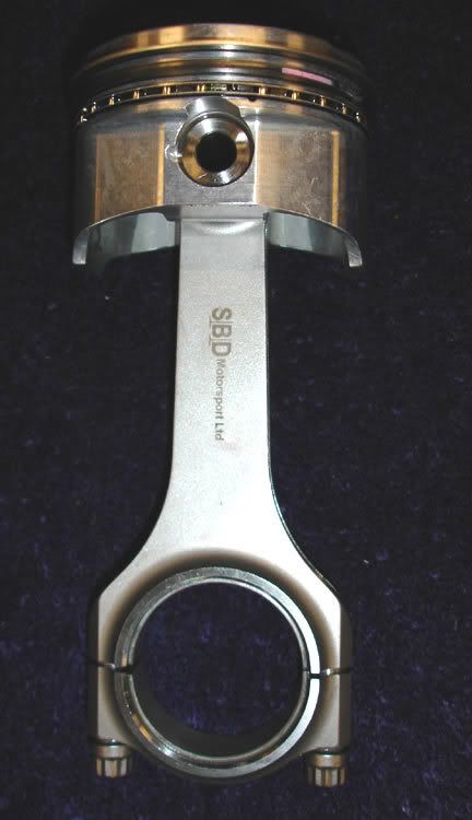
Picture of "floating" type piston + pin + rod:
(sorry for poor quality of this image, i didnt have a decent one of an engine me or stu has built so this is one i googled instead!)

There are two main types of pistons/pins, those where the pins are held in by circlips and can still move around a little in the piston, and those that are an interference fit meaning that they are locked solidly in place within the piston and dont move at all during engine operation.
To fit the "floating" type where you have circlips, its simply a matter of removing the clip from one side of the piston, holding the rod in place, and then pushing the pin through the piston and rod, and then reffitting the second clip to keep it all in place.
To fit the "interference fit" type, its essentially the same process but instead of just pushing the pin in by hand you will need to press it in, typically you will use some heat first to expand the hole to allow the pin to fit in more easily, then when it cools down it will be locked in place.
Fitted together they end up looking like this:
Attaching the pistons/rods to the crank/block
Im struggling to find any images ive saved of this, and a quick google didnt find any exactly waht im after either, so i will take some next time im building an engine and then update the topic, so its words only for parts of this section im afraid.
Remove the cap from the conrod and then offer the piston and rod into the bore from the top of the engine, the rings will need to be compressed with a piston ring compressor to allow them to fit into the bore.
You then slide the piston down the bore, so the rod pokes out of the bottom of the block near to the crank.
Install the bearing into the rod, and the position it against the journal on the crank, then fit the cap over this and fit the bolts in palce to hold it together.
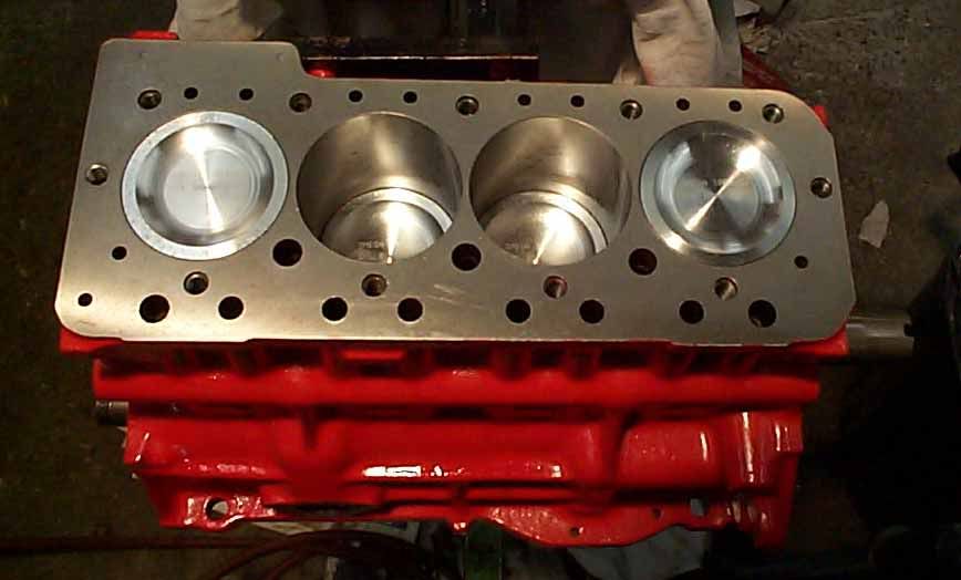
From the top it should now end up looking something like this picture of my engine i built for my mini many years ago:
Right this is a fairly big one, so im going to deal with it in the following chapters which i will add as i get the chance (may change as i go along):
Basic engine assembly
Piston:
clearances
ring gaps
rods:
weighing
length checking
perhaps touch on mods like shot peening and desseming and mention steel rods
little and big end size and ovality
crank:
taper on big ends . mains
end float
checking throw per cylinder
journal size + regrinds
block:
line boring and why its needed
rebores and important issues concerning reboring (ie taper) / ovality
"decking" the block, and piston deck height
the use of piston squirters or spray bars
stress removal
girdles
Basic engine assembly
Big difference between properly building an engine and assembling one,
so I will cover the assembly of one first as thats the easy bit!
Fitting the crank to the block
On the crank there are journals that sit in the bearings (the jounal is the round shiney bit!)
In order to fit the crank into the block, you first remove the "mains caps" form the block
block with mains caps still installed:
Then to fit the crank you first place one half of the bearing shell into the block on each of the mains, then you lift the crank into place, and then you fit the other half the bearings to each of the caps, then refit the caps in place over the crank and torque down.
First half of the bearings installed in the block:
Crank installed in the block, and hte mains caps refitted:
After doing this the crank should spin freely by hand
(a small amount of oil should be used as an assembly lubricant, no precise amounts invovled just smear a little on the bearing face and the journals)
Fitting the pistons to the rods
The pistons are attached to the rods (via the little ends, so called simply cause they are smaller than the big ends!)
There is no bearing here as such, the pin that goes through is the bearing basically.
Picture of "floating" type piston + pin + rod:
(sorry for poor quality of this image, i didnt have a decent one of an engine me or stu has built so this is one i googled instead!)
There are two main types of pistons/pins, those where the pins are held in by circlips and can still move around a little in the piston, and those that are an interference fit meaning that they are locked solidly in place within the piston and dont move at all during engine operation.
To fit the "floating" type where you have circlips, its simply a matter of removing the clip from one side of the piston, holding the rod in place, and then pushing the pin through the piston and rod, and then reffitting the second clip to keep it all in place.
To fit the "interference fit" type, its essentially the same process but instead of just pushing the pin in by hand you will need to press it in, typically you will use some heat first to expand the hole to allow the pin to fit in more easily, then when it cools down it will be locked in place.
Fitted together they end up looking like this:
Attaching the pistons/rods to the crank/block
Im struggling to find any images ive saved of this, and a quick google didnt find any exactly waht im after either, so i will take some next time im building an engine and then update the topic, so its words only for parts of this section im afraid.
Remove the cap from the conrod and then offer the piston and rod into the bore from the top of the engine, the rings will need to be compressed with a piston ring compressor to allow them to fit into the bore.
You then slide the piston down the bore, so the rod pokes out of the bottom of the block near to the crank.
Install the bearing into the rod, and the position it against the journal on the crank, then fit the cap over this and fit the bolts in palce to hold it together.
From the top it should now end up looking something like this picture of my engine i built for my mini many years ago:
Thread Starter
Banned
Joined: Dec 2002
Posts: 142
Likes: 1
PISTONS
(more photos to follow at a later date on this section)
sizeing pistons
Pistons will need to be measured to find out what their diameter is.
The quoted diameter is a guide only and they can vary by as much as a few thousandths of an inch.
So first we measure each piston accurately to determine its actual size.
We then write the size on the smallest, and then write the variation in size on the top of each of the others, this will be crucial when it comes to fitting them in the bores at a later date.
Number each piston too, so we know which one goes in which bore.
Piston to bore clearance
The important thing with regards to the width of the piston, is that we get the correct piston to bore clearance in the block. (see also the block section with regards to taper/ovality at this point!)
This is the amount smaller than the bore that the piston is.
It needs to be indivdually set for each piston.
The actual amount of clearance is application specific and can vary from about .0005" on a modern N/A engine with cast pistons right up to .005" on a turbo engine with forged pistons!
Piston rings
On the piston you will typically find 3 grooves, these are where the piston rings sit.
The first check that we need to do with these grooves is that there is the correct amount of height to the groove for the ring to sit in snugly without being too tight (refer to manufacturer for actual clearances required as its appication specific)
To measure this we place the ring in the grove and then check with a feeler gauge to see the clearance.
This isnt something you can adjust yourself, if its wrong you need to refer back to the person you bought the pistons and rings from, but you should check it just in case.
Its particuarly important in the case of using secondhand pistons and over time during hard use the ring lands can "close up" and become too tight.
The second thing to check with regards to the piston rings is that the "ring gap" is correct.
The ring gap is the space between the two ends that stop it making a full circle when its installed in the bore (without the piston)
This is checked by installing the ring into the bore and then using a set of feeler gauges to ascertain the gap.
EVERY ring must be checked in the bore to which its going to be isntalled, so its essential that you keep track of which rings are for which cylinder
Typically the top ring will have the largest gap, but check with your supplier what the required gaps are for each ring.
Trending Topics

10K+ Poster!!
Joined: Jun 2003
Posts: 10,788
Likes: 2
From: South Shields
chip - could you do a little post on plastiguages and how to use them.
from my understanding you basically put them on the bearing shell and tighten up the rod end / main cap bolt, then check the width of the strip against a chart to gauge the clearance between the bearing and the journal face. but do u use new bearings to do this? as if you used old ones it would give a different size to the new ones.
from my understanding you basically put them on the bearing shell and tighten up the rod end / main cap bolt, then check the width of the strip against a chart to gauge the clearance between the bearing and the journal face. but do u use new bearings to do this? as if you used old ones it would give a different size to the new ones.
Thread Starter
Banned
Joined: Dec 2002
Posts: 142
Likes: 1
Originally Posted by Red16
chip - could you do a little post on plastiguages and how to use them.
from my understanding you basically put them on the bearing shell and tighten up the rod end / main cap bolt, then check the width of the strip against a chart to gauge the clearance between the bearing and the journal face. but do u use new bearings to do this? as if you used old ones it would give a different size to the new ones.
from my understanding you basically put them on the bearing shell and tighten up the rod end / main cap bolt, then check the width of the strip against a chart to gauge the clearance between the bearing and the journal face. but do u use new bearings to do this? as if you used old ones it would give a different size to the new ones.
Other than to state that when dry building any engine you use EXACTLY the parts you will use in final assembly, so therefore when you plastigauge the bearings you would use the new ones.
10K+ Poster!!
Joined: Jun 2003
Posts: 10,788
Likes: 2
From: South Shields
Originally Posted by chip-3door
Originally Posted by Red16
chip - could you do a little post on plastiguages and how to use them.
from my understanding you basically put them on the bearing shell and tighten up the rod end / main cap bolt, then check the width of the strip against a chart to gauge the clearance between the bearing and the journal face. but do u use new bearings to do this? as if you used old ones it would give a different size to the new ones.
from my understanding you basically put them on the bearing shell and tighten up the rod end / main cap bolt, then check the width of the strip against a chart to gauge the clearance between the bearing and the journal face. but do u use new bearings to do this? as if you used old ones it would give a different size to the new ones.
Other than to state that when dry building any engine you use EXACTLY the parts you will use in final assembly, so therefore when you plastigauge the bearings you would use the new ones.
it means you could end up buying a set of new shells only to find out theyre no good for youre engine surely
Thread Starter
Banned
Joined: Dec 2002
Posts: 142
Likes: 1
Originally Posted by Red16
Originally Posted by chip-3door
Originally Posted by Red16
chip - could you do a little post on plastiguages and how to use them.
from my understanding you basically put them on the bearing shell and tighten up the rod end / main cap bolt, then check the width of the strip against a chart to gauge the clearance between the bearing and the journal face. but do u use new bearings to do this? as if you used old ones it would give a different size to the new ones.
from my understanding you basically put them on the bearing shell and tighten up the rod end / main cap bolt, then check the width of the strip against a chart to gauge the clearance between the bearing and the journal face. but do u use new bearings to do this? as if you used old ones it would give a different size to the new ones.
Other than to state that when dry building any engine you use EXACTLY the parts you will use in final assembly, so therefore when you plastigauge the bearings you would use the new ones.
it means you could end up buying a set of new shells only to find out theyre no good for youre engine surely
As for if its wrong, depends on why its wrong mate!
Could be that the bearing tunnel is oversize, so you dont have enough bearing clamping force (there should be a small amount of crush)
Could be that the crank is undersize
Could be that the bearing is too thin
If you get the wrong reading, you need to check why.
But before buying bearings in the first place, you should KNOW the other two are correct anyway, so you would NEVER regrind a crank as a result of a plastiguage result, only because you mic'd the journals and they were tapered or undersize.
Does that make sense?
Thread Starter
Banned
Joined: Dec 2002
Posts: 142
Likes: 1
Originally Posted by big_wig_074
i take it you mean put the ring in the bore to check the gap?as youve said piston but shown a ring in there!
I will know edit out the deliberate mistake


Professional Waffler

Joined: May 2003
Posts: 30,980
Likes: 9
From: barry-south wales
Originally Posted by big_wig_074
i take it you mean put the ring in the bore to check the gap?as youve said piston but shown a ring in there!

10K+ Poster!!
Joined: Jun 2003
Posts: 10,788
Likes: 2
From: South Shields
Originally Posted by RichardPON
Chip,
Having never built an engine................
How do the bearings sit in the block?
Having never built an engine................
How do the bearings sit in the block?
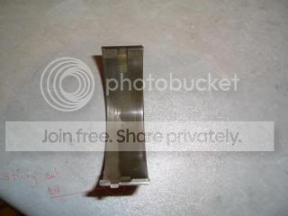
these pics will show you what i mean, since i modified them for the tutorial
bearing and main cap

bearing shell
Originally Posted by RichardPON
Chip,
Having never built an engine................
How do the bearings sit in the block?
Having never built an engine................
How do the bearings sit in the block?
good read tho chip cheers!

Too many posts.. I need a life!!
Joined: May 2004
Posts: 925
Likes: 0
From: in the garage fixing yet another oil leak
excellent thread chip - exactly what one subject area this site should focus on.
would say however, that you may become the agony aunt of YB's
"well you said blah blah blah .. so i decided to rebuild it myself"
would say however, that you may become the agony aunt of YB's
"well you said blah blah blah .. so i decided to rebuild it myself"
Thread Starter
Banned
Joined: Dec 2002
Posts: 142
Likes: 1
Yep as above the shells just rest in.
The thing stopping them spinning is a combination of bearing crush from the caps, and the presense of a tab thats stops them rotation.
Will try and do another chapter or two over the weekend at some point
The thing stopping them spinning is a combination of bearing crush from the caps, and the presense of a tab thats stops them rotation.
Will try and do another chapter or two over the weekend at some point

Too many posts.. I need a life!!
Joined: May 2004
Posts: 672
Likes: 0
Fitting pistons into the block:
1. Use a piston compressor to carefully compress the rings into their grooves:

Make sure that some piston projects under the compressor tool - you need this to ensure the piston will be able to be squarely pushed into the bore.

2. Ensure everything is sitting squarely:

3. Use a blunt soft object - for example the shaft of a hammer - to sharply whack the piston into it's bore:

Fast, hard, but short - you dont want to project the piston and rod straight through the block to be damaged on the workshop floor.
4. Job done. Drink a cup of tea and admire your pistons, it will be the last time you'll see them (hopefully).

1. Use a piston compressor to carefully compress the rings into their grooves:
Make sure that some piston projects under the compressor tool - you need this to ensure the piston will be able to be squarely pushed into the bore.
2. Ensure everything is sitting squarely:
3. Use a blunt soft object - for example the shaft of a hammer - to sharply whack the piston into it's bore:
Fast, hard, but short - you dont want to project the piston and rod straight through the block to be damaged on the workshop floor.
4. Job done. Drink a cup of tea and admire your pistons, it will be the last time you'll see them (hopefully).

 for the weekend crew

PassionFord Post Troll
iTrader: (2)
Joined: May 2003
Posts: 3,067
Likes: 2
From: In my garage, coventry
Interesting thread
I just hope people can afford the F**k UPs
IF they try building an engine for themselves
after reading this thread
But i suppose you have to start somewhere
I WOULD rather attempt building a lesser engine first
Like a daily run around
Than having a go at building my performance engine that i had just saved and saved up for all the bits
And then finding
I hadnt done it right
and it all having to come appart
Not a negative post all though it may sound like it
Just want people to be aware it isnt as easy as it sounds
AS you stated Chip this is very VERY basic engine build
It will take you a long time to list every mineute detail
Good luck
Thread Starter
Banned
Joined: Dec 2002
Posts: 142
Likes: 1
Crank preperation.
On the crank there are two sets of journals, mains that sit in the bearings in the block, and big ends which sit inside the bearings in the conrod.
There are only really two things of any real concern to us with regards to the journals on the crank:
Are they the right size?
Are they the right shape?
There is a third of course, which is that there is no visually obvious damage such as scoring or pitting.
You need to check with the manufacturer of your engine (or crank if non standard) to see what the recomended maximum and minimum tolerance for journal size are.
Now with regards to shape, the journals should be perfect cylinders, there should be no taper, and there should be no ovality.
Ovality = deviation from round, as measured around the journal
Taper = deviation from straight, as measured along the journal
The first thing to do is to measure the size of the journal, this is done by using a micrometer, and it needs to be accurate to around a tenth of a thousandth of an inch. If you cant get down to this level of accuracy then just dont bother trying, get someone else to do it for you, even a couple of tenths of power of taper is enough for a very shortneded engine life.
Once we have a size by measuring the journal in the centre, we then check the size either side, and if there is any difference it shows that the journal is tapered, which means that all the force will be acting on one side of the bearing, which leads at best to premature bearing wear, and at worst to a terminal bearing failure such as a spun shell.
To check for ovality we simple measure at different points around the journal, i only ever do this in the centre of each journal but you could repeat at both ends if you really want to, this (ovality) is almost never a problem on cranks (but very common on the bearing tunnel the crank sits in, but i will cover that in the blocks section), but is worth checking while you have the right tool here anyway, as it can lead to shock loads to the bearings in the unlikely event it is ovalled.
You must check EVERY journal, do not just measure one and assume that because its ok the next one will be too.
The other thing we are interested in with regards to the crank is the throw of it, this should be the same on all cylinders, its not actually amazingly important if there is a slight deviation in throw from spec, providing its the same deviation on all cylinders, the key thing we are looking for is the location of the piston at the top of the bore to not alter the CR greatly, its posistion at the bottom has less of a marked effect on CR
The stroke itself is not the easiest thing to measure to be perfectly honest, as its hard to get an accurate distance when the piston is at the bottom of the bore to any usefully small degree of accuracy, well unless you fancy piling up 80mm of slip gauges on the top of your piston
The way that i personally do a quick "sanity check" on the throw of the crank is after dry building to simple check the deckheight in the bores, its perfectly possible that in doing so you end up with one cylinder having slightly more throw on the crank but cancelled out by a slightly shorter piston and rod assembly, but if this happens the effects on CR from a tiny bit of extra flow are negligable outside of things like formula one!
If you do have any variation in deck height you can often correct it by swapping the rods and pistons about, especially if you have spare ones too this process is known as "selective assembly".
However if when you measure the deck heights you find a varation that increases as you make your way from cylinder to cylinder, then its a good indication that the bearing tunnel is out of true with the top of the block, if this is the case, then the block will need machining to correct this fault (if possible witout pushing the CR through the roof), see block section later on in this thread for details of how to ensure the tunnel is true to the block.
NOTE - Deckheight = the height of the piston in the bore when at TDC (just in case that confused anyone!)
Modifications to cranks for performance use.
Not going to go into too much depth here for two main reasons:
1: Nothing here that the home builder can really adjust for themselves
2: I dont know enough about it myself as its always been something ive paid others to do (See reason 1!)
knife edging the crank = Machining the crank so that the leading edge as it roates end as a sharp edge (not razor sharp, just relative to standard) rather than being a a very thick edge, the reason for this is to allow the crank to cut through the oil with less resistance at high RPM, which leads to less of a loss in horsepower from the resistance of the oil
balancing the crank = This is just like doing it on a wheel/tyre! the crank is spun on a machine that measures the oscilation up and down to determine where the crank is out of balance, and its then corrected by removing material to even the weight, this is done either by drlling holes or by machining off a portion of the surface, i actually know one engine builder who uses an angle grinder to do this initially to reomve fairly large chunks of metal, sounds like an horrific bodge, but if you know what you are doing its actually an acceptable way to make quick progress in getting the crank into the right ballpark for final adjustment!
lightening the crank = The idea behind lightening the crank is simply to remove rotational mass so as to allow the engine to rev more freely, this is generally not something you would wish to do on a road car, and IMHO there is never any point doing so until you have first lightened the flywheel as thats weight all at one end which is worse than spread through the crank in terms of loading up the crank and bearings under high rpm usage
cross drilling the journals = on some cranks its beneficial to instroduce a second feed hold from the main to the big end in order to ensure agood supply of oil to the big end, this is vey application specific though and expert advice must be sort before you perform this sort of modification as it can result in weakening the crank or excessive oil flow leading to a drop in pressure

Advanced PassionFord User
Joined: Jun 2003
Posts: 1,797
Likes: 0
From: The BLACK COUNTRY
Good thread mate
Thought I would post a few pics of my own rebuild
It will be an 8v N/A Pinto using the following bottom end
Cozzy 200 4x4 Block and rods
94mm Accralite pistons
4x4 Crank - Lightened, knife edged and full balance to 8000rpm (as an assembly)


Thought I would post a few pics of my own rebuild
It will be an 8v N/A Pinto using the following bottom end
Cozzy 200 4x4 Block and rods
94mm Accralite pistons
4x4 Crank - Lightened, knife edged and full balance to 8000rpm (as an assembly)
Thread Starter
Banned
Joined: Dec 2002
Posts: 142
Likes: 1
Fantastic pictures, espeically of the work to the crank
Shame you havent got a before picture as well!
To be honest mate i feel you have TOTALLY missed the point.
My own take on things (i may of course be wrong!) is this:
Anyone who was thinking of building an engine anyway and thought it was a walk in the park and just needed assembling in the way i have started the thread off, will see from this thread (when its finished) whats involved, and be MORE likely to take it to an engine builder instead as when you start to think about things like a crank having 2 thou of taper being enough to kill your engine and needing the equipment to find out if it has or not its likely to put you off building one not encourage you to build one.
Also when someone like Stu quotes you a grand, and if you ask for a breakdown will probably tell you that 800 of that is 2 days spent "measuring and machining things" and only 200 is to actually build it, you are more liklely to understand WHY it costs that much money
(NOT actual figures!!!!)
Shame you havent got a before picture as well!
Originally Posted by Alg1k
Interesting thread
I just hope people can afford the F**k UPs
IF they try building an engine for themselves
after reading this thread
But i suppose you have to start somewhere
I WOULD rather attempt building a lesser engine first
Like a daily run around
Than having a go at building my performance engine that i had just saved and saved up for all the bits
And then finding
I hadnt done it right
and it all having to come appart
Not a negative post all though it may sound like it
Just want people to be aware it isnt as easy as it sounds
AS you stated Chip this is very VERY basic engine build
It will take you a long time to list every mineute detail
Good luck
I just hope people can afford the F**k UPs
IF they try building an engine for themselves
after reading this thread
But i suppose you have to start somewhere
I WOULD rather attempt building a lesser engine first
Like a daily run around
Than having a go at building my performance engine that i had just saved and saved up for all the bits
And then finding
I hadnt done it right
and it all having to come appart
Not a negative post all though it may sound like it
Just want people to be aware it isnt as easy as it sounds
AS you stated Chip this is very VERY basic engine build
It will take you a long time to list every mineute detail
Good luck
My own take on things (i may of course be wrong!) is this:
Anyone who was thinking of building an engine anyway and thought it was a walk in the park and just needed assembling in the way i have started the thread off, will see from this thread (when its finished) whats involved, and be MORE likely to take it to an engine builder instead as when you start to think about things like a crank having 2 thou of taper being enough to kill your engine and needing the equipment to find out if it has or not its likely to put you off building one not encourage you to build one.
Also when someone like Stu quotes you a grand, and if you ask for a breakdown will probably tell you that 800 of that is 2 days spent "measuring and machining things" and only 200 is to actually build it, you are more liklely to understand WHY it costs that much money
(NOT actual figures!!!!)