Any Electronic wizards in here ???
 25-02-2014, 05:30 PM
#1
PassionFord Post Whore!!
Thread Starter
iTrader: (1)

Join Date: Jun 2003
Location: Under the Missus ( . )( . )
Posts: 5,847
Likes: 0
Received 0 Likes
on
0 Posts
I have purchased a tunit box and looking at it have had a possible idea to make it a bit better  . Its for a bmw 530d by the way lol
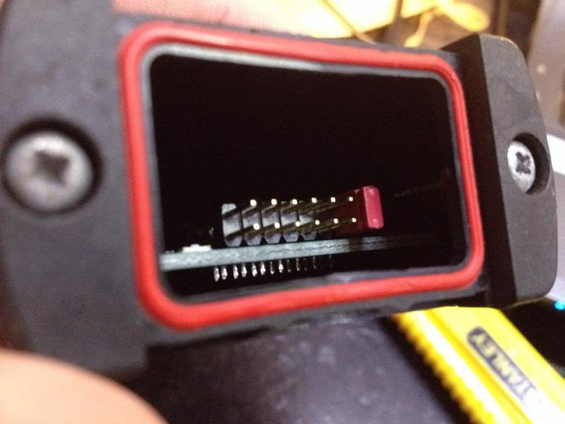
As you can see from pic below it has 7 rows of 2 pins which depending where you put the red plug (far right) dictates which of the 7 fuel/boost maps it runs. Now looking at the red plug I'm assuming it just completes a circuit from top pin to bottom pin selecting that map out of the 7 built into the box. So you basically pick the one you want and your stuck with that until you want to change it by opening bonnet and moving red plug
Now my idea is if possible lengthen the wiring and put box IN car and somehow get a plug or solder wires onto pins in box and then somehow wire in a 7 way knob so I can control which map I want at any given time from in car. So ideally if just cruising around on low setting maximising fuel and then for more spirited driving just turning the knob for more boost/fuel. using something similar to this below ???
http://www.maplin.co.uk/p/2-pole-6-w...y-switch-ff74r
Any ideas or views on this ???
As you can see from pic below it has 7 rows of 2 pins which depending where you put the red plug (far right) dictates which of the 7 fuel/boost maps it runs. Now looking at the red plug I'm assuming it just completes a circuit from top pin to bottom pin selecting that map out of the 7 built into the box. So you basically pick the one you want and your stuck with that until you want to change it by opening bonnet and moving red plug

Now my idea is if possible lengthen the wiring and put box IN car and somehow get a plug or solder wires onto pins in box and then somehow wire in a 7 way knob so I can control which map I want at any given time from in car. So ideally if just cruising around on low setting maximising fuel and then for more spirited driving just turning the knob for more boost/fuel. using something similar to this below ???
http://www.maplin.co.uk/p/2-pole-6-w...y-switch-ff74r
Any ideas or views on this ???
 25-02-2014, 05:35 PM
#2
Advanced PassionFord User

Join Date: Apr 2009
Location: Bridgend, South Wales
Posts: 1,623
Likes: 0
Received 16 Likes
on
12 Posts
You do know these boxes are just a resistor right? They just increases the fuel pressure but tricking the ECU into thinking the fuel pressure is lower than is actually is.
All your doing by moving the pin is picking a resistance.
I assume the rotary switch will have a 'common' and then you move the switched output to different pins? In which case it would only work if one side of the pins on the box was 'common'.
Then if you did want to move the box inside the car then you're going to want to be carefull about the conductor sizes and lengths as you don't want to increase that resistance further.
Personally I would send it back and get a remap.
Last edited by Bailes1992; 25-02-2014 at 05:37 PM.
25-02-2014, 05:41 PM
#3
PassionFord Post Whore!!
Thread Starter
iTrader: (1)
Join Date: Jun 2003
Location: Under the Missus ( . )( . )
Posts: 5,847
Likes: 0
Received 0 Likes
on
0 Posts
yes I know it just a resistance box of sorts but I don't drive balls out these days so for wot I paid I'm happy to have the little extra it gives and if I can control it even further and gain a few extra miles per gallon which will be the main aim and have extra horses when needed i'll be happy with that
And the way I was thinking about it was solder wires onto each pin in box and then mate them up with there partner if red plug was plugged in but solder the 2 wires together onto 1 pin on back of the 6 way switch as above then depending on where knob was would select that map ????
And looking at the wiring on box I can put it in car without lengthening wire so only extra wire would just be from pins to knob and back
Last edited by 3drstretch; 25-02-2014 at 05:46 PM.
 25-02-2014, 06:00 PM
#6
PassionFord Post Whore!!

And the back of the board?
I'm assuming one row will be all joined together, and the other row are the signal pins.
A ribbon cable plug will fit on the pins, then you can split out the ribbon to connect to your switch.
You need a switch like this:

Edit to add, I think your Maplin switch will be like this, but you'll be able to pick 6 different maps. All relies on them being commoned up on the board though.
I'm assuming one row will be all joined together, and the other row are the signal pins.
A ribbon cable plug will fit on the pins, then you can split out the ribbon to connect to your switch.
You need a switch like this:
Edit to add, I think your Maplin switch will be like this, but you'll be able to pick 6 different maps. All relies on them being commoned up on the board though.
Last edited by St3V3_C; 25-02-2014 at 06:04 PM.
25-02-2014, 06:01 PM
#7
Advanced PassionFord User
Join Date: Apr 2009
Location: Bridgend, South Wales
Posts: 1,623
Likes: 0
Received 16 Likes
on
12 Posts
Bit more in there than I've seen before!
I seen one previously that a friend fitted to his car.
It was just a load of resistors and you moved the pin to adjust the resistance.
You need to find out if one half of the pins (the lower half) are common to eachother!
If not then we'll have to think of something else!
I seen one previously that a friend fitted to his car.
It was just a load of resistors and you moved the pin to adjust the resistance.
You need to find out if one half of the pins (the lower half) are common to eachother!
If not then we'll have to think of something else!
Trending Topics
 25-02-2014, 06:12 PM
#10
PassionFord Post Whore!!
Actually, if they are not common's on the board that switch will still work as it's 2 pole - which should be this:

So, you join the two commons on the switch to each other.
Then 1a to your top left pin, and 1b to your bottom left pin on the board.
Move across - 2a and 2b.
etc.
Easy lol.
So, you join the two commons on the switch to each other.
Then 1a to your top left pin, and 1b to your bottom left pin on the board.
Move across - 2a and 2b.
etc.
Easy lol.
Last edited by St3V3_C; 25-02-2014 at 06:17 PM.
25-02-2014, 07:01 PM
#13
PassionFord Post Whore!!
Thread Starter
iTrader: (1)
Join Date: Jun 2003
Location: Under the Missus ( . )( . )
Posts: 5,847
Likes: 0
Received 0 Likes
on
0 Posts
actually looking again if the dark green lines are the circuits the bottom line by red plug looks to be common to all bottom pins so how would I wire that in ?? or do you fancy earning some beer tokens steve as I'm only over bridge from you

Thread
Thread Starter
Forum
Replies
Last Post
Roosie
General Car Related Discussion.
27
19-08-2015 12:16 AM