Cosworth exhaust manifolds, hopefully a technical discussion
 22-11-2006, 12:52 AM
#1

MikeR will love this one i suspect 
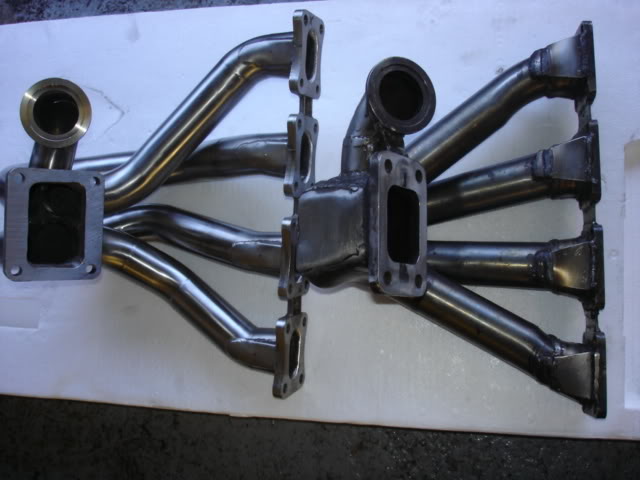
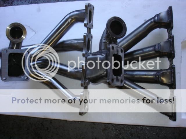
Ok, here we have 3 manifolds for cosworths, I believe i have posted them in order of worst at the top, and best at the bottom, my criteria isnt quality of build or welds etc, merely the design.
Particuarly the external wastegate take off.
Manifold 1, this looks TERRIBLE to me, the gasses come all from cylinders 1 and 2, and they have to double back on themselves to make it to the gate.

Manifold 2, same basic problems, to a certain extent although this time at least seem to be joined at the collector so can at least see a certain amount of flow from all cylinders and is "only" a 90 degree bend:

Manifold 3, i like this one, shallow angle take off to the wastegate, and seems to be well accessed from all 4 cylinders easily.

(my sexy blonde secratary will hopefully replace that pic with a better one for me asap)
So, are my opinions correct?
Any other comments on the relative merits of the three designs?
Ok, here we have 3 manifolds for cosworths, I believe i have posted them in order of worst at the top, and best at the bottom, my criteria isnt quality of build or welds etc, merely the design.
Particuarly the external wastegate take off.
Manifold 1, this looks TERRIBLE to me, the gasses come all from cylinders 1 and 2, and they have to double back on themselves to make it to the gate.
Manifold 2, same basic problems, to a certain extent although this time at least seem to be joined at the collector so can at least see a certain amount of flow from all cylinders and is "only" a 90 degree bend:
Manifold 3, i like this one, shallow angle take off to the wastegate, and seems to be well accessed from all 4 cylinders easily.
(my sexy blonde secratary will hopefully replace that pic with a better one for me asap)
So, are my opinions correct?
Any other comments on the relative merits of the three designs?
 22-11-2006, 01:07 AM
#2
10K+ Poster!!

iTrader: (9)
Join Date: May 2004
Location: birmingham west mids
Posts: 11,919
Likes: 0
Received 11 Likes
on
9 Posts
I belive martin H made a manifold adaptor for the 2wd cast manifold that took the wastegate off at 90 degrees on the small swan-neck part of the 2wd manifold, and even with NO wastegate fitted he couldn't bleed enough boost off to control the turbo safley  can't remember who told me that story, but it speaks volumes on how critical gasflow and manifold design become at high power levels
can't remember who told me that story, but it speaks volumes on how critical gasflow and manifold design become at high power levels
22-11-2006, 01:12 AM
#3
Originally Posted by RWD_cossie_wil
I belive martin H made a manifold adaptor for the 2wd cast manifold that took the wastegate off at 90 degrees on the small swan-neck part of the 2wd manifold, and even with NO wastegate fitted he couldn't bleed enough boost off to control the turbo safley can't remember who told me that story, but it speaks volumes on how critical gasflow and manifold design become at high power levels
can't remember who told me that story, but it speaks volumes on how critical gasflow and manifold design become at high power levelsEXACTLY my point on these manifolds (except the 3rd one)


Trending Topics
22-11-2006, 07:32 AM
#8
Originally Posted by foreigneRS
Originally Posted by martin-reyland
who's manifold is the first one?
http://www.petergproduction.com/
22-11-2006, 07:36 AM
#9
PassionFord Post Troll

Heres one i made earlier!
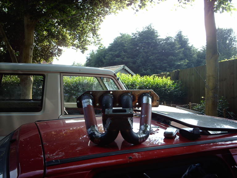
Not exactly in the same league but only cost �20 to produce.
The external gate (not shown) was added to the back of the collector at an angle of approx 60 degrees.
It seems to control boost very well and there have been no issues with cracking.
While we are on the subject of exhausts does any one no where i can get some calcs to work out the length and diameter of primaries on a n/a exhaust?
I have a tried some but want to double check them.
 22-11-2006, 08:05 AM
#15
PassionFord's crazy fool!
Join Date: May 2004
Location: Leeds, West Yorkshire
Posts: 7,102
Likes: 0
Received 0 Likes
on
0 Posts
Well I'm non technical but can certainly see from the third manifold that the gases appear to have more or less a straight run through to the wastegate, without being obstructed which can only be good 
22-11-2006, 08:22 AM
#16
Originally Posted by Mike Rainbird
As far as I can see you have answered all your own questions .
.Yeah but i wanted someone who actually knows shit from putty to come along and correct me if i got something wrong
22-11-2006, 08:25 AM
#17
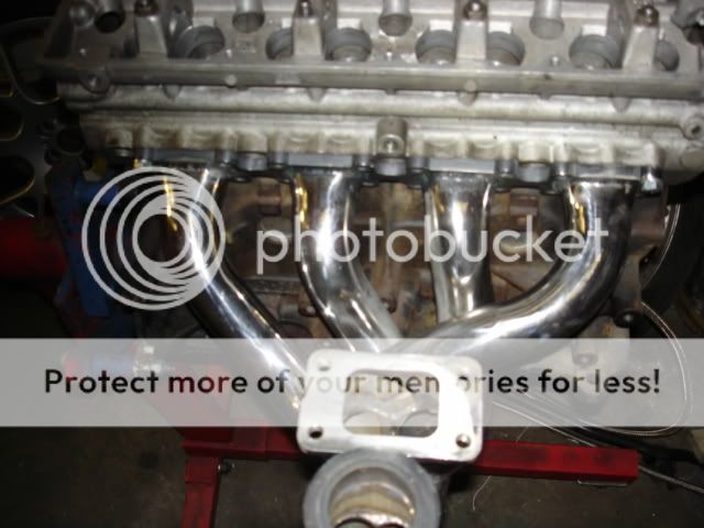
Originally Posted by martin-reyland
Prototype and finished product, the wastegate take off looks at first glance to be a bad angle BUT i have seen 1bar of boost at 7500rpm, might go lower but have not yet tried.
Interesting stuff, it does indeed look like a terrible angle for a take off, but obviously its fine for what you need for your particular application if it goes as low as 1 bar of boost at 7500rpm, as it seems pretty unlikely on a car like yours you are going to want to go any lower.
22-11-2006, 08:27 AM
#18
Originally Posted by chip-3door
Originally Posted by Mike Rainbird
As far as I can see you have answered all your own questions .
.Yeah but i wanted someone who actually knows shit from putty to come along and correct me if i got something wrong
 yo' ass, I would have "jumped at" the opportunity
 !
22-11-2006, 08:32 AM
!
22-11-2006, 08:32 AM
#19
Originally Posted by Mike Rainbird
Originally Posted by chip-3door
Originally Posted by Mike Rainbird
As far as I can see you have answered all your own questions .
.Yeah but i wanted someone who actually knows shit from putty to come along and correct me if i got something wrong
yo' ass, I would have "jumped at" the opportunity !Do you mean that harvey is engaged then, or did he agree with me, it was the organ grinders opinion i was after ideally
Can you post the figures you put up once before about what boost the r and b one can restrict to etc?
22-11-2006, 08:36 AM
#20
I never have a problem getting through, I have all his numbers  .
.
GT30 @ 7500rpm, Tial 46mm wastegate, boost can be dropped to single figures .
.
I would point out that the bigger wastegate is obviously a key issure here, as most people use the cheaper, smaller versions.
GT30 @ 7500rpm, Tial 46mm wastegate, boost can be dropped to single figures
I would point out that the bigger wastegate is obviously a key issure here, as most people use the cheaper, smaller versions.
22-11-2006, 09:10 AM
#21
Originally Posted by Mike Rainbird
I never have a problem getting through, I have all his numbers .
GT30 @ 7500rpm, Tial 46mm wastegate, boost can be dropped to single figures.
I would point out that the bigger wastegate is obviously a key issure here, as most people use the cheaper, smaller versions.
GT30 @ 7500rpm, Tial 46mm wastegate, boost can be dropped to single figures
I would point out that the bigger wastegate is obviously a key issure here, as most people use the cheaper, smaller versions.
Not just down to the gate though of course, if martin was finding even without the gate present he was still not getting enough air bypassing the turbo.
22-11-2006, 09:15 AM
#22
PassionFord Post Troll
Originally Posted by Mike Rainbird
I never have a problem getting through, I have all his numbers .
GT30 @ 7500rpm, Tial 46mm wastegate, boost can be dropped to single figures.
I would point out that the bigger wastegate is obviously a key issure here, as most people use the cheaper, smaller versions.
GT30 @ 7500rpm, Tial 46mm wastegate, boost can be dropped to single figures
I would point out that the bigger wastegate is obviously a key issure here, as most people use the cheaper, smaller versions.
Can't ever see Col running this little boost at that point but it shows its not really that difficult a task to construct and externally gated manifold that will allow good boost control. Certainly not rocket science.
22-11-2006, 09:21 AM
#23
Originally Posted by Garage19
Originally Posted by Mike Rainbird
I never have a problem getting through, I have all his numbers .
GT30 @ 7500rpm, Tial 46mm wastegate, boost can be dropped to single figures.
I would point out that the bigger wastegate is obviously a key issure here, as most people use the cheaper, smaller versions.
GT30 @ 7500rpm, Tial 46mm wastegate, boost can be dropped to single figures
I would point out that the bigger wastegate is obviously a key issure here, as most people use the cheaper, smaller versions.
Can't ever see Col running this little boost at that point but it shows its not really that difficult a task to construct and externally gated manifold that will allow good boost control. Certainly not rocket science.
22-11-2006, 09:39 AM
#24
Wahay!! I've lost my Virginity!!

Join Date: Nov 2006
Location: swe
Posts: 65
Likes: 0
Received 0 Likes
on
0 Posts
the first "peterg"manifold is the best of these 3 shown imo, but not optimum. (cant see reylands pipe on this machine, at work)
i would never put the wg outlet in outer bend of a pipe, the flow will follow the outward wall and hit the wg outlet and make lots of turbulence disturbing turbo spoolup and drive. Keyparameters for optimum turbodrive in my opinion: As short pipes as ever possible to take all pulse-energy to drive turbine, As straight pipes as possible to keep the pulse alive, place the wg in innerbend of a pipe to disturb as little as possible. Audi has made prototypes with holedrilled plates to cover the wg outlet that flow just enough to decrease boostpressure, but disturb the gasflow to the turbo less. I have made insane good results with my prototype manifolds on cosworth engines, have some running on rally and hillclimb cars.
Regards
22-11-2006, 09:45 AM
#25
Originally Posted by msport
the first "peterg"manifold is the best of these 3 shown imo, but not optimum. (cant see reylands pipe on this machine, at work)
i would never put the wg outlet in outer bend of a pipe, the flow will follow the outward wall and hit the wg outlet and make lots of turbulence disturbing turbo spoolup and drive. Keyparameters for optimum turbodrive in my opinion: As short pipes as ever possible to take all pulse-energy to drive turbine, As straight pipes as possible to keep the pulse alive, place the wg in innerbend of a pipe to disturb as little as possible. Audi has made prototypes with holedrilled plates to cover the wg outlet that flow just enough to decrease boostpressure, but disturb the gasflow to the turbo less. I have made insane good results with my prototype manifolds on cosworth engines, have some running on rally and hillclimb cars.
Regards
i would never put the wg outlet in outer bend of a pipe, the flow will follow the outward wall and hit the wg outlet and make lots of turbulence disturbing turbo spoolup and drive. Keyparameters for optimum turbodrive in my opinion: As short pipes as ever possible to take all pulse-energy to drive turbine, As straight pipes as possible to keep the pulse alive, place the wg in innerbend of a pipe to disturb as little as possible. Audi has made prototypes with holedrilled plates to cover the wg outlet that flow just enough to decrease boostpressure, but disturb the gasflow to the turbo less. I have made insane good results with my prototype manifolds on cosworth engines, have some running on rally and hillclimb cars.
Regards
Ah, thats an interesting reply, and was exactly the sort of contradictory argument I was looking for all along
Looking at it from totally the other point of view there to how most of us on here do, ie concentrating on the maximum power capability of the manifold as opposed to the maximum ability to control boost.
See now this seems interesting to me, basically develop the manifold so that with no gate at all, it just manages to bleed off enough gasses for the minimum boost requirement that you have, then only use the wastegate to increase the boost from there.
Which would make Martin's manifold perfect for his application of course
Mine and Mike's "control is everything" opinion of manifolds is only really of relevance on a road car, for a true performance application, I can see the flip side of the coin
22-11-2006, 09:49 AM
#26
PassionFord Post Troll
Originally Posted by msport
the first "peterg"manifold is the best of these 3 shown imo, but not optimum. (cant see reylands pipe on this machine, at work)
i would never put the wg outlet in outer bend of a pipe, the flow will follow the outward wall and hit the wg outlet and make lots of turbulence disturbing turbo spoolup and drive. Keyparameters for optimum turbodrive in my opinion: As short pipes as ever possible to take all pulse-energy to drive turbine, As straight pipes as possible to keep the pulse alive, place the wg in innerbend of a pipe to disturb as little as possible. Audi has made prototypes with holedrilled plates to cover the wg outlet that flow just enough to decrease boostpressure, but disturb the gasflow to the turbo less. I have made insane good results with my prototype manifolds on cosworth engines, have some running on rally and hillclimb cars.
Regards
i would never put the wg outlet in outer bend of a pipe, the flow will follow the outward wall and hit the wg outlet and make lots of turbulence disturbing turbo spoolup and drive. Keyparameters for optimum turbodrive in my opinion: As short pipes as ever possible to take all pulse-energy to drive turbine, As straight pipes as possible to keep the pulse alive, place the wg in innerbend of a pipe to disturb as little as possible. Audi has made prototypes with holedrilled plates to cover the wg outlet that flow just enough to decrease boostpressure, but disturb the gasflow to the turbo less. I have made insane good results with my prototype manifolds on cosworth engines, have some running on rally and hillclimb cars.
Regards
22-11-2006, 09:56 AM
#28
Originally Posted by chip-3door
Originally Posted by msport
the first "peterg"manifold is the best of these 3 shown imo, but not optimum. (cant see reylands pipe on this machine, at work)
i would never put the wg outlet in outer bend of a pipe, the flow will follow the outward wall and hit the wg outlet and make lots of turbulence disturbing turbo spoolup and drive. Keyparameters for optimum turbodrive in my opinion: As short pipes as ever possible to take all pulse-energy to drive turbine, As straight pipes as possible to keep the pulse alive, place the wg in innerbend of a pipe to disturb as little as possible. Audi has made prototypes with holedrilled plates to cover the wg outlet that flow just enough to decrease boostpressure, but disturb the gasflow to the turbo less. I have made insane good results with my prototype manifolds on cosworth engines, have some running on rally and hillclimb cars.
Regards
i would never put the wg outlet in outer bend of a pipe, the flow will follow the outward wall and hit the wg outlet and make lots of turbulence disturbing turbo spoolup and drive. Keyparameters for optimum turbodrive in my opinion: As short pipes as ever possible to take all pulse-energy to drive turbine, As straight pipes as possible to keep the pulse alive, place the wg in innerbend of a pipe to disturb as little as possible. Audi has made prototypes with holedrilled plates to cover the wg outlet that flow just enough to decrease boostpressure, but disturb the gasflow to the turbo less. I have made insane good results with my prototype manifolds on cosworth engines, have some running on rally and hillclimb cars.
Regards
Ah, thats an interesting reply, and was exactly the sort of contradictory argument I was looking for all along
Looking at it from totally the other point of view there to how most of us on here do, ie concentrating on the maximum power capability of the manifold as opposed to the maximum ability to control boost.
See now this seems interesting to me, basically develop the manifold so that with no gate at all, it just manages to bleed off enough gasses for the minimum boost requirement that you have, then only use the wastegate to increase the boost from there.
Which would make Martin's manifold perfect for his application of course
Mine and Mike's "control is everything" opinion of manifolds is only really of relevance on a road car, for a true performance application, I can see the flip side of the coin
22-11-2006, 10:00 AM
#29
Originally Posted by martin-reyland
my manifold may allow less than 1 bar boost, 1 bar was the presure we started with when gaining boost control... i will pump some figures into the ECU and see how little boost i can have at top end BUT 1 bar is more than acceptable.
That would be interesting info
Do you individual EGT's vary with when the wastegate is operating or not?
(due to it being to one side i mean)
22-11-2006, 10:04 AM
#30
Originally Posted by chip-3door
Originally Posted by martin-reyland
my manifold may allow less than 1 bar boost, 1 bar was the presure we started with when gaining boost control... i will pump some figures into the ECU and see how little boost i can have at top end BUT 1 bar is more than acceptable.
Do you individual EGT's vary with when the wastegate is operating or not?
(due to it being to one side i mean)
22-11-2006, 10:08 AM
#31
Originally Posted by martin-reyland
Originally Posted by chip-3door
Originally Posted by martin-reyland
my manifold may allow less than 1 bar boost, 1 bar was the presure we started with when gaining boost control... i will pump some figures into the ECU and see how little boost i can have at top end BUT 1 bar is more than acceptable.
Do you individual EGT's vary with when the wastegate is operating or not?
(due to it being to one side i mean)
And even if it does you can trim it out on the fuelling or timing for that cylinder on your T6 anyway
Just be interesting to see the results, however small as it all works towards making us all a little less thick, lol
22-11-2006, 10:18 AM
#33
Originally Posted by Mike Rainbird
Have not experienced symptoms of the turbulence described in either dyno testing or on the road.
Your car might make 10bhp more due to less pumping losses if the turbulance wasnt there, but without trying the manifold with the wastegate hole sealed up, how would you know it was suffering?
22-11-2006, 10:23 AM
#34
Wahay!! I've lost my Virginity!!
Join Date: Nov 2006
Location: swe
Posts: 65
Likes: 0
Received 0 Likes
on
0 Posts
You wont "experience" turbulence as in an airplane, it only shows in lack of performance as late boost buildup, bad response/pickup, and even backpressure. When it all works great you will see the difference.
Yes I have pictures, wont bring them up here, PM if emailadress if interested. I have a complete turbo/manifold/WG package for sale makes 700+bhp(658bhp done easy, cant use due to new restrictor rules)
I had foe example 2.4bar boost, never more than 1.4bar backpressure. 0.5bar 7500rpm 422bhp, those who know understands something is made with care.
I am not typing this to claim im the best, just a tip that things can be better. I am willing to listen to all experiences and ideas also.
Regards
22-11-2006, 10:25 AM
#35


Originally Posted by msport
the first "peterg"manifold is the best of these 3 shown imo, but not optimum. (cant see reylands pipe on this machine, at work)
i would never put the wg outlet in outer bend of a pipe, the flow will follow the outward wall and hit the wg outlet and make lots of turbulence disturbing turbo spoolup and drive. Keyparameters for optimum turbodrive in my opinion: As short pipes as ever possible to take all pulse-energy to drive turbine, As straight pipes as possible to keep the pulse alive, place the wg in innerbend of a pipe to disturb as little as possible. Audi has made prototypes with holedrilled plates to cover the wg outlet that flow just enough to decrease boostpressure, but disturb the gasflow to the turbo less. I have made insane good results with my prototype manifolds on cosworth engines, have some running on rally and hillclimb cars.
Regards
i would never put the wg outlet in outer bend of a pipe, the flow will follow the outward wall and hit the wg outlet and make lots of turbulence disturbing turbo spoolup and drive. Keyparameters for optimum turbodrive in my opinion: As short pipes as ever possible to take all pulse-energy to drive turbine, As straight pipes as possible to keep the pulse alive, place the wg in innerbend of a pipe to disturb as little as possible. Audi has made prototypes with holedrilled plates to cover the wg outlet that flow just enough to decrease boostpressure, but disturb the gasflow to the turbo less. I have made insane good results with my prototype manifolds on cosworth engines, have some running on rally and hillclimb cars.
Regards
22-11-2006, 10:27 AM
#36
Wahay!! I've lost my Virginity!!
Join Date: Nov 2006
Location: swe
Posts: 65
Likes: 0
Received 0 Likes
on
0 Posts
Originally Posted by Stu @ M Developments
Originally Posted by msport
the first "peterg"manifold is the best of these 3 shown imo, but not optimum. (cant see reylands pipe on this machine, at work)
i would never put the wg outlet in outer bend of a pipe, the flow will follow the outward wall and hit the wg outlet and make lots of turbulence disturbing turbo spoolup and drive. Keyparameters for optimum turbodrive in my opinion: As short pipes as ever possible to take all pulse-energy to drive turbine, As straight pipes as possible to keep the pulse alive, place the wg in innerbend of a pipe to disturb as little as possible. Audi has made prototypes with holedrilled plates to cover the wg outlet that flow just enough to decrease boostpressure, but disturb the gasflow to the turbo less. I have made insane good results with my prototype manifolds on cosworth engines, have some running on rally and hillclimb cars.
Regards
i would never put the wg outlet in outer bend of a pipe, the flow will follow the outward wall and hit the wg outlet and make lots of turbulence disturbing turbo spoolup and drive. Keyparameters for optimum turbodrive in my opinion: As short pipes as ever possible to take all pulse-energy to drive turbine, As straight pipes as possible to keep the pulse alive, place the wg in innerbend of a pipe to disturb as little as possible. Audi has made prototypes with holedrilled plates to cover the wg outlet that flow just enough to decrease boostpressure, but disturb the gasflow to the turbo less. I have made insane good results with my prototype manifolds on cosworth engines, have some running on rally and hillclimb cars.
Regards
22-11-2006, 10:28 AM
#37
Originally Posted by msport
Originally Posted by Stu @ M Developments
Originally Posted by msport
the first "peterg"manifold is the best of these 3 shown imo, but not optimum. (cant see reylands pipe on this machine, at work)
i would never put the wg outlet in outer bend of a pipe, the flow will follow the outward wall and hit the wg outlet and make lots of turbulence disturbing turbo spoolup and drive. Keyparameters for optimum turbodrive in my opinion: As short pipes as ever possible to take all pulse-energy to drive turbine, As straight pipes as possible to keep the pulse alive, place the wg in innerbend of a pipe to disturb as little as possible. Audi has made prototypes with holedrilled plates to cover the wg outlet that flow just enough to decrease boostpressure, but disturb the gasflow to the turbo less. I have made insane good results with my prototype manifolds on cosworth engines, have some running on rally and hillclimb cars.
Regards
i would never put the wg outlet in outer bend of a pipe, the flow will follow the outward wall and hit the wg outlet and make lots of turbulence disturbing turbo spoolup and drive. Keyparameters for optimum turbodrive in my opinion: As short pipes as ever possible to take all pulse-energy to drive turbine, As straight pipes as possible to keep the pulse alive, place the wg in innerbend of a pipe to disturb as little as possible. Audi has made prototypes with holedrilled plates to cover the wg outlet that flow just enough to decrease boostpressure, but disturb the gasflow to the turbo less. I have made insane good results with my prototype manifolds on cosworth engines, have some running on rally and hillclimb cars.
Regards

 22-11-2006, 10:36 AM
#39
Wahay!! I've lost my Virginity!!
Join Date: Nov 2006
Location: swe
Posts: 65
Likes: 0
Received 0 Likes
on
0 Posts
Originally Posted by Stu @ M Developments
Originally Posted by msport
Originally Posted by Stu @ M Developments
Originally Posted by msport
the first "peterg"manifold is the best of these 3 shown imo, but not optimum. (cant see reylands pipe on this machine, at work)
i would never put the wg outlet in outer bend of a pipe, the flow will follow the outward wall and hit the wg outlet and make lots of turbulence disturbing turbo spoolup and drive. Keyparameters for optimum turbodrive in my opinion: As short pipes as ever possible to take all pulse-energy to drive turbine, As straight pipes as possible to keep the pulse alive, place the wg in innerbend of a pipe to disturb as little as possible. Audi has made prototypes with holedrilled plates to cover the wg outlet that flow just enough to decrease boostpressure, but disturb the gasflow to the turbo less. I have made insane good results with my prototype manifolds on cosworth engines, have some running on rally and hillclimb cars.
Regards
i would never put the wg outlet in outer bend of a pipe, the flow will follow the outward wall and hit the wg outlet and make lots of turbulence disturbing turbo spoolup and drive. Keyparameters for optimum turbodrive in my opinion: As short pipes as ever possible to take all pulse-energy to drive turbine, As straight pipes as possible to keep the pulse alive, place the wg in innerbend of a pipe to disturb as little as possible. Audi has made prototypes with holedrilled plates to cover the wg outlet that flow just enough to decrease boostpressure, but disturb the gasflow to the turbo less. I have made insane good results with my prototype manifolds on cosworth engines, have some running on rally and hillclimb cars.
Regards
22-11-2006, 10:38 AM
#40
Originally Posted by SapphyMike
i dont understand this talk of 1 bar at the top?
can someone explain please?
thanks
can someone explain please?
thanks