
Dyno Dynamics experts please look inside

AT on a graph = ambient temp
IT on a graph = intake temp
Please can you tell me where you would expect each of these probes to be found out of the following:
1 ) outside the building
2 ) inside the cell away from the car
3 ) inside the cell near to the air filter
4 ) inside the boost pipework
Serious answers only please.
Thanks.


i might have learnt soemthing from the posts previously dealing with these things so i would hazard a guess at:
AT = 2
IT = 4 (assuming it's in the pipework ratehr than pointing in the general direction of the air filter)
AT = 2
IT = 4 (assuming it's in the pipework ratehr than pointing in the general direction of the air filter)

Trending Topics

AT - 2
IT - 3
If the probe is in the intake it wont correctly sample the air temp due to the probe sampling temps of the pipe itself (heat soak), rather than the air passing through it. Which is traveling that quick it wont have time to even think of stopping to warm up.
IT - 3
If the probe is in the intake it wont correctly sample the air temp due to the probe sampling temps of the pipe itself (heat soak), rather than the air passing through it. Which is traveling that quick it wont have time to even think of stopping to warm up.

The hotter the intake temp the more power the Dyno will add to the correction factor.
The probe would gradually get hotter and hotter and hotter over a period of runs and that engine would be getting more powerful each time

 what an engine!

The general rule-of-thumb is a tolerance of up to 8� between AT and IT before it starts compensating by an amount that may not be believeable. We certainly prefer to see these kinds of figures.
Thankyou for your input lads.
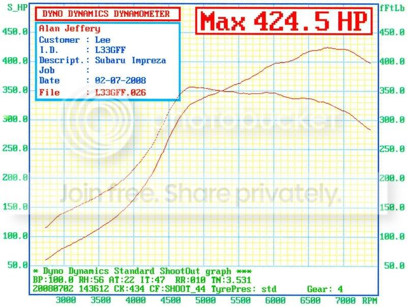
Was trying to explain something to someone, and they thought I was making it up about IT giving mis readings.
Here is the graph we were discussing:
Was trying to explain something to someone, and they thought I was making it up about IT giving mis readings.
Here is the graph we were discussing:
so, when it's described as "intake" what is being taking in?
thank you please

Too many posts.. I need a life!!
Joined: May 2003
Posts: 742
Likes: 0
From: NORWICH

i try and keep them the same much better for tuning as you know if you make a change in map you can see change in graph rather than thinking its a correction on power for intake temps!!!

PassionFord Post Troll
Joined: Jul 2004
Posts: 3,446
Likes: 1
From: Nr Ipswich

Testing the future
Joined: Jul 2003
Posts: 17,597
Likes: 24
From: W. Sussex
why try to do anything? surely they should be used as intended to measure, not be fudged?
Too many posts.. I need a life!!
Joined: May 2003
Posts: 742
Likes: 0
From: NORWICH
i dont use the sensor in the airfilter as they just end up with figures like the graph above
when mapping with the inlet temp probe near filter after a few runs on dyno it can increase so figures become inflated
so mine hangs at side of cell
when mapping with the inlet temp probe near filter after a few runs on dyno it can increase so figures become inflated
so mine hangs at side of cell
We try to get the IT probe in the vicinty of air of a similar temp to that being consumed by the engine, so in the cell close to the car is good, but not in the engine bay.
If its in the engine bay itself, the air is much hotter there and not a true reflection of the actual intake temp because the air going into the engine hasn't been in the engine bay long enough to get that hot. That's my slant on it anyway.
If its in the engine bay itself, the air is much hotter there and not a true reflection of the actual intake temp because the air going into the engine hasn't been in the engine bay long enough to get that hot. That's my slant on it anyway.
Testing the future
Joined: Jul 2003
Posts: 17,597
Likes: 24
From: W. Sussex
We try to get the IT probe in the vicinty of air of a similar temp to that being consumed by the engine, so in the cell close to the car is good, but not in the engine bay.
If its in the engine bay itself, the air is much hotter there and not a true reflection of the actual intake temp because the air going into the engine hasn't been in the engine bay long enough to get that hot. That's my slant on it anyway.
If its in the engine bay itself, the air is much hotter there and not a true reflection of the actual intake temp because the air going into the engine hasn't been in the engine bay long enough to get that hot. That's my slant on it anyway.
On the graph in question, the person informs me the intake temp probe was put INSIDE his boost pipework.
I personally think he MUST have that incorrect, as I just dont see logistically how you would get it in there, but on the other hand it certainly looks like it was!
I personally think he MUST have that incorrect, as I just dont see logistically how you would get it in there, but on the other hand it certainly looks like it was!
that's nonsense. it should be in the intake so that it measures intake air temperature. unless it has a huge thermal mass, the sensor will read the actual temperature of the air being ingested by the engine in that position (wether it has been heated above the AT or not).


Too many posts.. I need a life!!
Joined: May 2003
Posts: 742
Likes: 0
From: NORWICH
that's nonsense. it should be in the intake so that it measures intake air temperature. unless it has a huge thermal mass, the sensor will read the actual temperature of the air being ingested by the engine in that position (wether it has been heated above the AT or not).

We try to get the IT probe in the vicinty of air of a similar temp to that being consumed by the engine, so in the cell close to the car is good, but not in the engine bay.
If its in the engine bay itself, the air is much hotter there and not a true reflection of the actual intake temp because the air going into the engine hasn't been in the engine bay long enough to get that hot. That's my slant on it anyway.
If its in the engine bay itself, the air is much hotter there and not a true reflection of the actual intake temp because the air going into the engine hasn't been in the engine bay long enough to get that hot. That's my slant on it anyway.
one side of me thinks that putting it as close to the actual inlet manifold as possible because then you have the actual temprature of the air that is being used by the engine, after it's gone through whatever induction pipework form the air filter, as possible to see what sort of fueling you would need
the other side of me thinks that it should be placed at the air filter side so that you know the temp of the air coming in, and that the sensor may misread due to it being cooled/heated by the air rushing past in the inlet manifold and generally being hotter than it should due to the heat coming from the engine
is there a difiniative right or wrong answer to this or does it depend on the operator in question?
Because if you dont, then you could run your car up on a very cold day and get a massively inflated figure that it wouldnt be able to adjust back down, likewise the opposite on a hot day.
And because if you build two identical engines and roller one on a hot day and one on a cold day they would get totally different figures.
How the hell is that useful for developing an engine?
Any engine from december would seem massively better than any engine you built in july!
And because if you build two identical engines and roller one on a hot day and one on a cold day they would get totally different figures.
How the hell is that useful for developing an engine?
Any engine from december would seem massively better than any engine you built in july!
Last edited by Chip; Nov 26, 2008 at 09:04 AM.
Its supposed to be a measure of the temperature of air going into the air filter.
Where you choose to get a reading from to represent that is a matter of some debate, but not a lot, essentially it needs to be somewhere between the air filter and the dyno wall, where you think it best respresents the actual temperature of air that will go into the air filter, often putting it to close will result in it picking up radiant energy from hot engine components that will make the sensor hot but wont heat up the air going in to the same extent.
Im with Gary in that two far away is better than too close if you have to be either.
On a turbo car, putting it AFTER the turbo is always going to make it think the air coming into the air filter was hotter than it really was as the turbo compresses the air, which heats it up! (pv=nrt)
Where you choose to get a reading from to represent that is a matter of some debate, but not a lot, essentially it needs to be somewhere between the air filter and the dyno wall, where you think it best respresents the actual temperature of air that will go into the air filter, often putting it to close will result in it picking up radiant energy from hot engine components that will make the sensor hot but wont heat up the air going in to the same extent.
Im with Gary in that two far away is better than too close if you have to be either.
one side of me thinks that putting it as close to the actual inlet manifold as possible because then you have the actual temprature of the air that is being used by the engine, after it's gone through whatever induction pipework form the air filter, as possible to see what sort of fueling you would need
the other side of me thinks that it should be placed at the air filter side so that you know the temp of the air coming in, and that the sensor may misread due to it being cooled/heated by the air rushing past in the inlet manifold and generally being hotter than it should due to the heat coming from the engine
is there a difiniative right or wrong answer to this or does it depend on the operator in question?
that's nonsense. it should be in the intake so that it measures intake air temperature. unless it has a huge thermal mass, the sensor will read the actual temperature of the air being ingested by the engine in that position (wether it has been heated above the AT or not).
