
Fitting a cam cover mounted phase sensor to a YB

Thread Starter
aka Turbosailorboy
iTrader: (5)
Joined: Apr 2005
Posts: 6,527
Likes: 21
From: Under the water.... .......in a nuclear submarine
Having converted to coilpacks i decided to completely remove the dizzy. Removing the dizzy meant moving the phase sensor to the cam cover Grp A style. The removal of the dizzy required an oil pump drive as well.
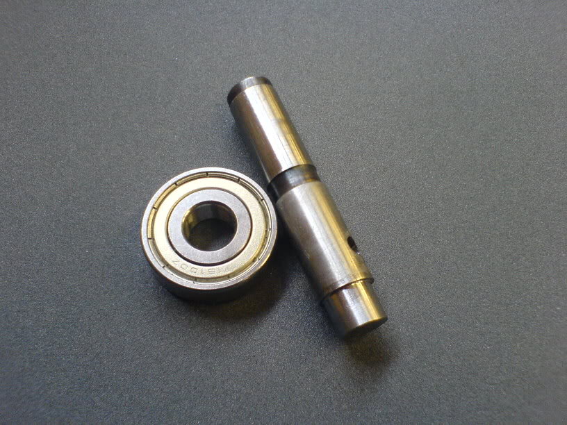
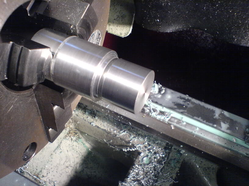
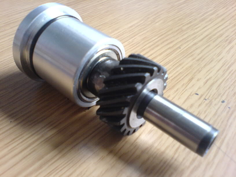
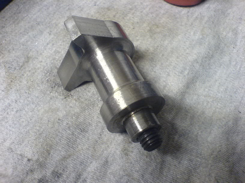
Firstly i made an oil pump drive by cutting the dizzy in half and machining the shaft to take a bearing
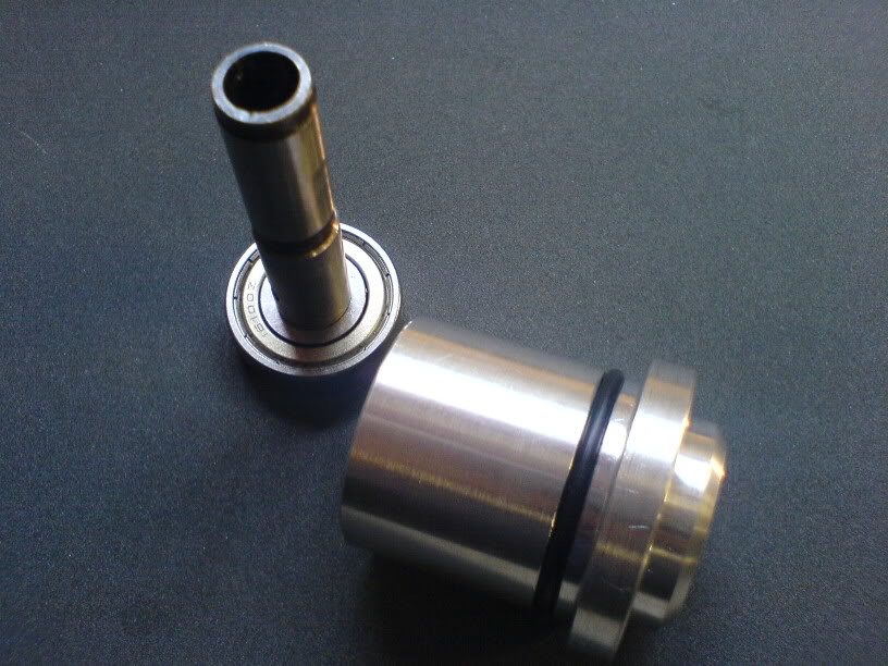
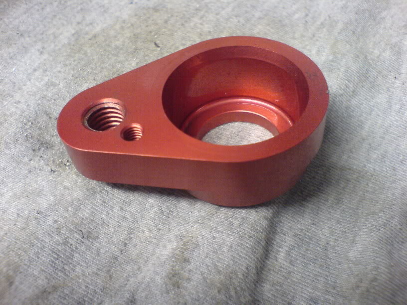
Then made a housing to fit in the block
Then pressed the two bits together
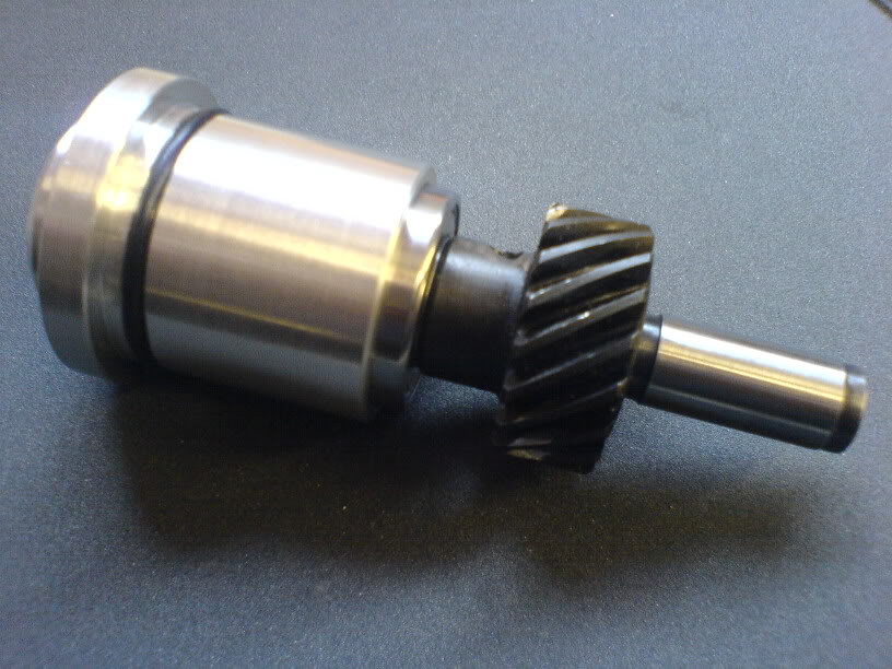
To give
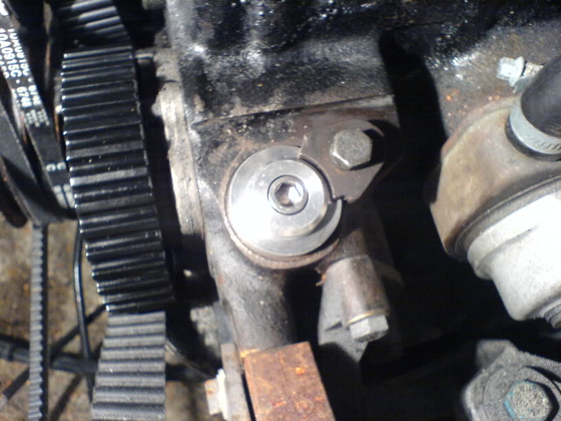
And finally fitted to the engine
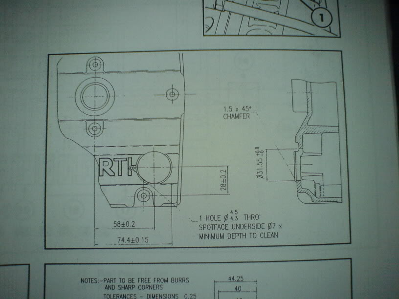
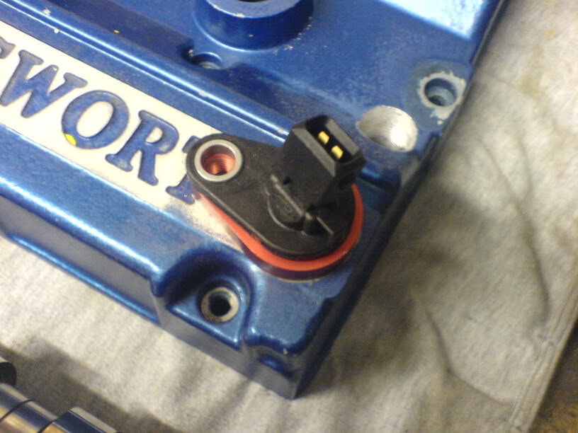
To fit the phase sensor in the cam cover you need to machine the cover to take the sensor holder
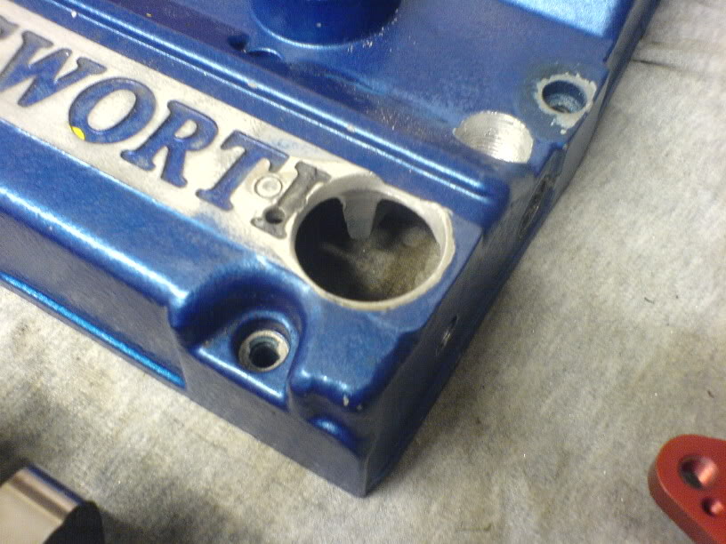
I then got the sensor, holder and phase sensor trigger. Available from Mountune or Zoo.
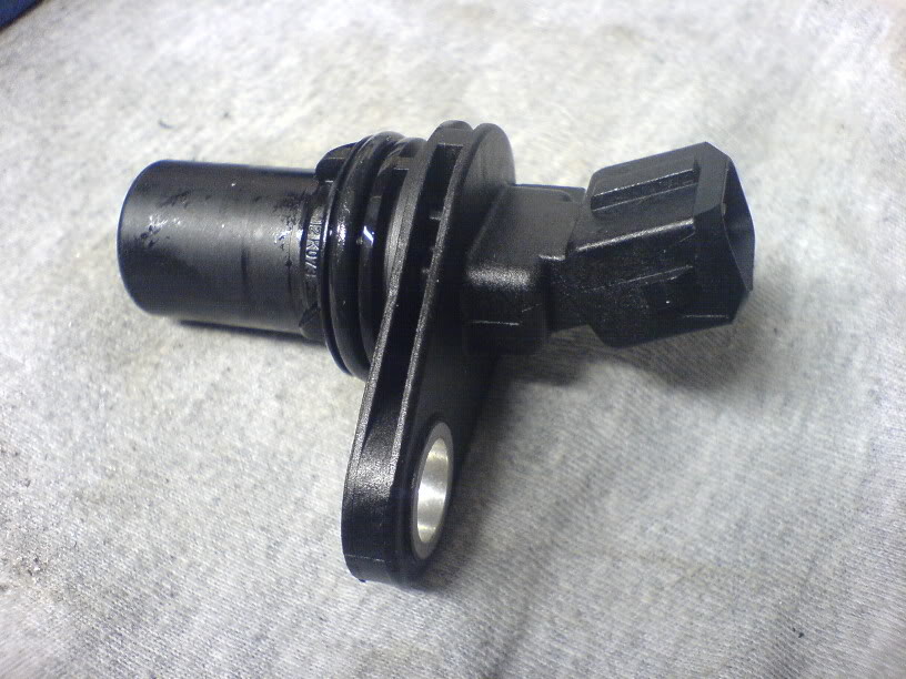
The sensor and holder fitted to cam cover
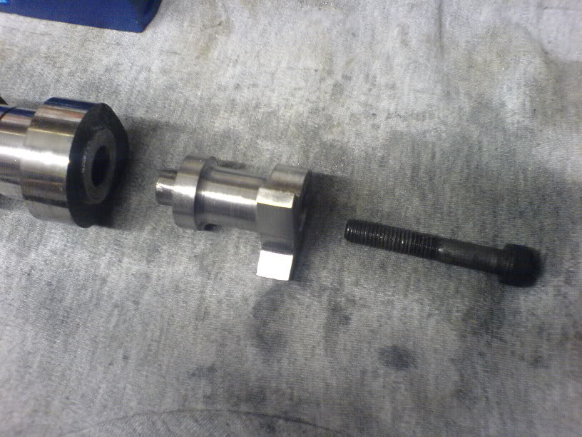
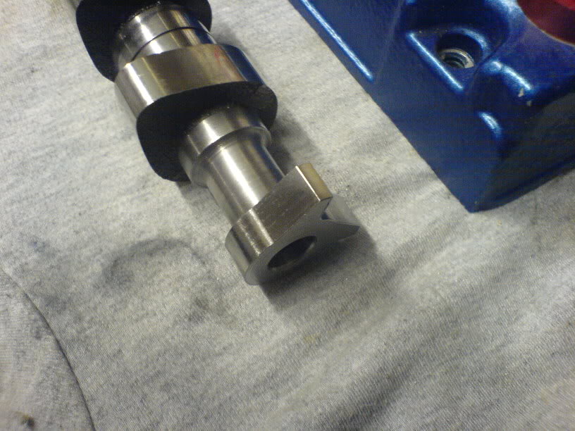
The cam requires machining to take the trigger
Thanks to Martin@Reyland for that bit of machining
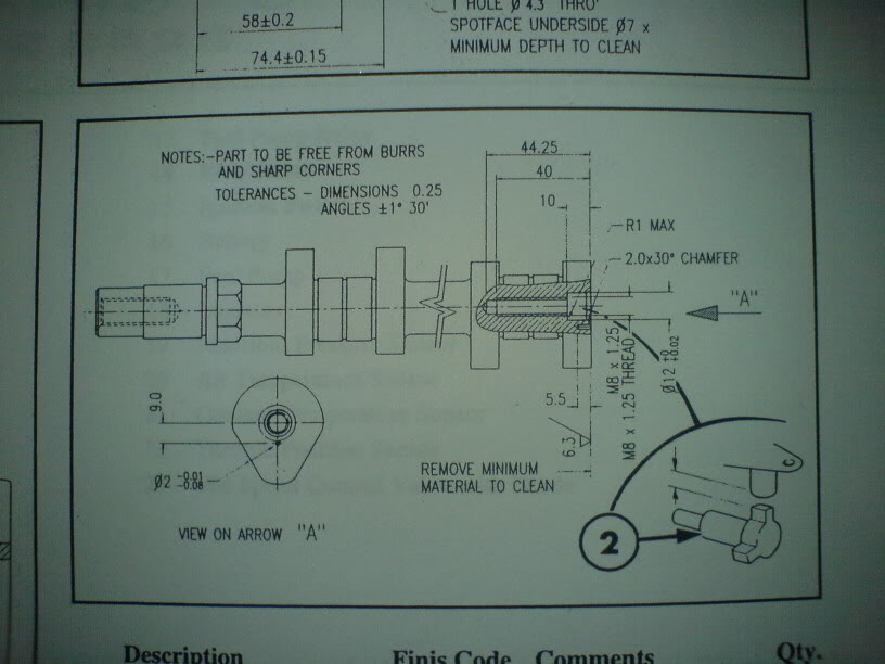
The trigger then bolts into the end of the cam
Next update will be the timing of the phase sensor to the cam and final fitting of the cam and cover.
Firstly i made an oil pump drive by cutting the dizzy in half and machining the shaft to take a bearing
Then made a housing to fit in the block
Then pressed the two bits together
To give
And finally fitted to the engine
To fit the phase sensor in the cam cover you need to machine the cover to take the sensor holder
I then got the sensor, holder and phase sensor trigger. Available from Mountune or Zoo.
The sensor and holder fitted to cam cover
The cam requires machining to take the trigger
Thanks to Martin@Reyland for that bit of machining
The trigger then bolts into the end of the cam
Next update will be the timing of the phase sensor to the cam and final fitting of the cam and cover.


Trending Topics
Thread Starter
aka Turbosailorboy
iTrader: (5)
Joined: Apr 2005
Posts: 6,527
Likes: 21
From: Under the water.... .......in a nuclear submarine
Originally Posted by Franco
Has is been timed yet Rich??
Richie,
Did you machine the cover for the sensor, if so were the schematics supplied with the kit?
Also why did you give the cam to martin to machine? by all accounts you're more than skilled for the job?
Really going to be interested to how this is timed up!!
Did you machine the cover for the sensor, if so were the schematics supplied with the kit?
Also why did you give the cam to martin to machine? by all accounts you're more than skilled for the job?
Really going to be interested to how this is timed up!!
Originally Posted by Franco
Richie,
Did you machine the cover for the sensor, if so were the schematics supplied with the kit?
Also why did you give the cam to martin to machine? by all accounts you're more than skilled for the job?
Really going to be interested to see how this is timed up!!
Did you machine the cover for the sensor, if so were the schematics supplied with the kit?
Also why did you give the cam to martin to machine? by all accounts you're more than skilled for the job?
Really going to be interested to see how this is timed up!!
Thread Starter
aka Turbosailorboy
iTrader: (5)
Joined: Apr 2005
Posts: 6,527
Likes: 21
From: Under the water.... .......in a nuclear submarine
Originally Posted by Franco
Well i for one know this engines finished!
So finish the post slacker!!
So finish the post slacker!!
Originally Posted by july1
I guess you've add the bolt on top to help the removal?
I've found that life I needed.. It's HERE!!
Joined: Aug 2003
Posts: 1,223
Likes: 0
From: Northwest
Hi B9 Kos,
Could you give me the dimensions of the silver bung (with the o ring around it).
I need to make one as I dont need the dizzy or the oil pump drive.
Cheers,
WD
Could you give me the dimensions of the silver bung (with the o ring around it).
I need to make one as I dont need the dizzy or the oil pump drive.
Cheers,
WD

I've found that life I needed.. It's HERE!!
Joined: Aug 2003
Posts: 1,223
Likes: 0
From: Northwest
Just got my sensor and was wondering about the clearance it needs to run properly :
The cam extension lobes - fixed height.
The mounting flange - fixed thickness.
The rocker cover thickness - variable depending on refurbs etc
Should I put a washer between the sensor and mounting flange to put it back to 'approximatley' it's design height.
Cheers,
WD
The cam extension lobes - fixed height.
The mounting flange - fixed thickness.
The rocker cover thickness - variable depending on refurbs etc
Should I put a washer between the sensor and mounting flange to put it back to 'approximatley' it's design height.
Cheers,
WD
According the GpA manual your are supposed to 'clean' the peint on the cam cover and fit shims between the houssing and the cover (not between the sensor and the housing) better if you have to change quickly the sensor between two stages but for us I guess it doesn't make a big differance as long as you have the correct gap
I'm waiting my new cams to machine the whole things to do the same
I'm waiting my new cams to machine the whole things to do the same
I've found that life I needed.. It's HERE!!
Joined: Aug 2003
Posts: 1,223
Likes: 0
From: Northwest
Does anyone know what the correct gap is ?
I had approx 0.5mm less gap then the length of sensor. I put a 1.00mm washer between the sensor and housing so I now have approx 0.5mm clearance.
Based on the crank sensor spec this is OK but is it also OK for the cam sensor ? I guess the cam sensor could cope with quite large clearances as the magnet in it is really stong (compared to the crank sensor) and the lobes it talks to are also bigger

Many thanks


to get the dimensions to make your own oil pump drive just pull your dizzy out & measure it .
the cap head screw is there purely as a means for getting the oil pump drive out again ,i.e. undo bolt grab with pliers & pull .
ps i know this is a old thread but it still needs more information to complete this conversion .
pps i do not need the info as i already done my car but i have been asked by pm but i can not remember it all .
Last edited by andy escos; Jul 11, 2011 at 10:05 PM.


Thread
Thread Starter
Forum
Replies
Last Post
muz
General Car Related Discussion.
3
Aug 16, 2015 12:57 PM
Zoggon
Ford Sierra/Sapphire/RS500 Cosworth
5
Aug 10, 2015 10:39 AM