Old Apr 30, 2006 | 10:43 PM
  #1  
Richie.'s Avatar
Richie.
aka Turbosailorboy
iTrader: (5)
 
Joined: Apr 2005
Posts: 6,527
Likes: 21
From: Under the water.... .......in a nuclear submarine
Default Fitting a cam cover mounted phase sensor to a YB

Having converted to coilpacks i decided to completely remove the dizzy. Removing the dizzy meant moving the phase sensor to the cam cover Grp A style. The removal of the dizzy required an oil pump drive as well.

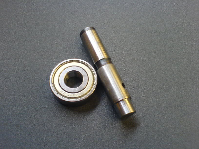
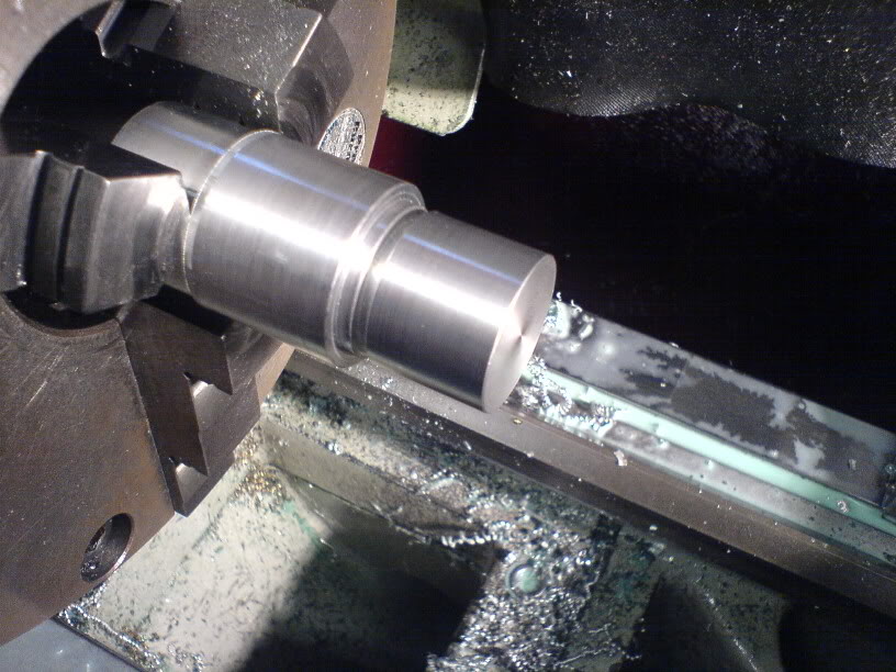
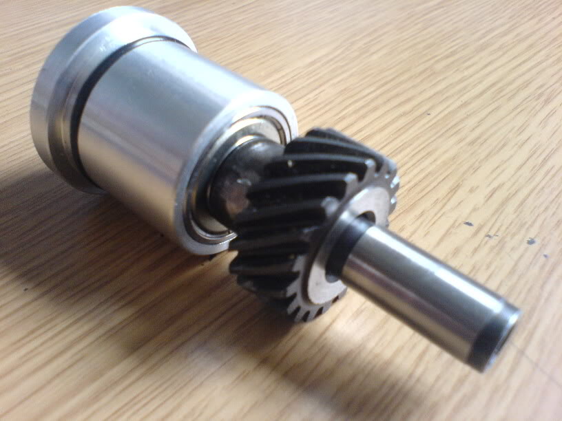
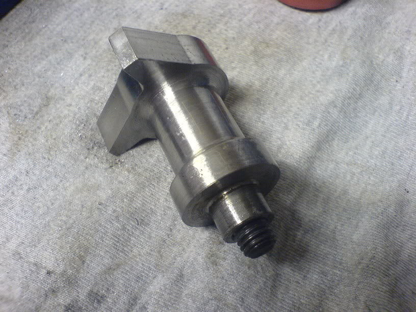
Firstly i made an oil pump drive by cutting the dizzy in half and machining the shaft to take a bearing

Name:  DSC00276.jpg
Views: 1215
Size:  108.3 KB

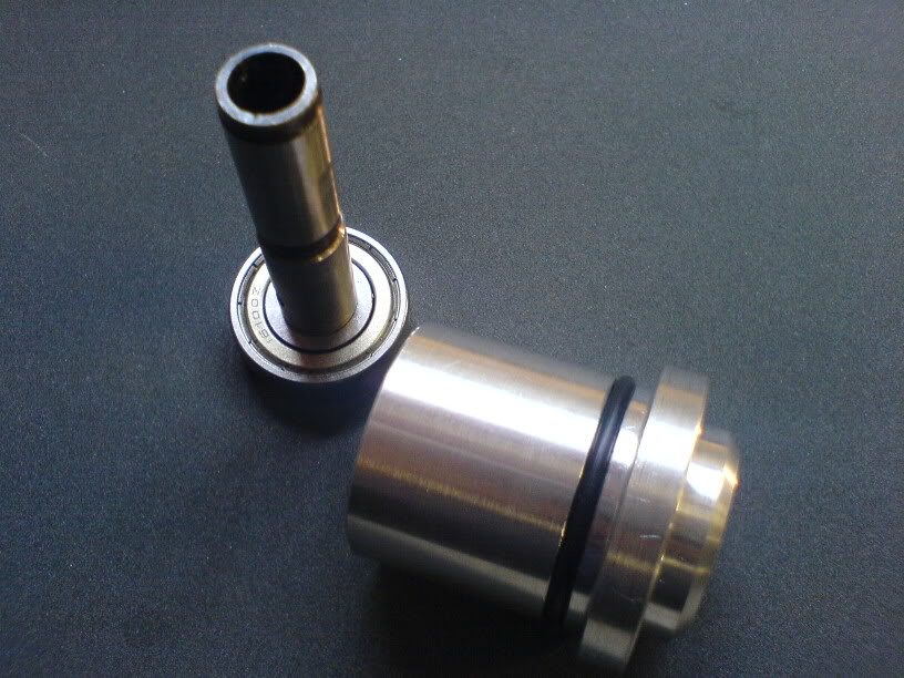
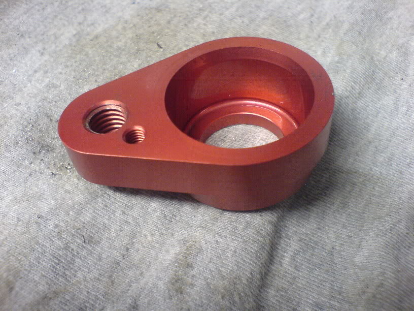
Then made a housing to fit in the block

Name:  DSC00275.jpg
Views: 1084
Size:  97.6 KB

Then pressed the two bits together
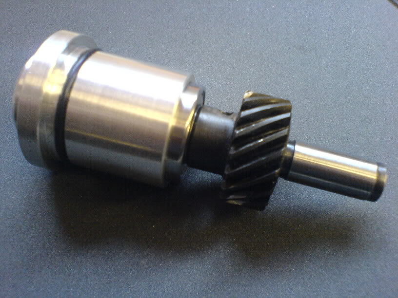
Name:  DSC00279.jpg
Views: 1114
Size:  86.0 KB
Name:  DSC00280.jpg
Views: 1304
Size:  86.0 KB

To give

Name:  DSC00292.jpg
Views: 1158
Size:  64.1 KB

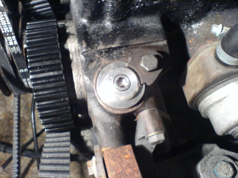
And finally fitted to the engine

Name:  DSC00295.jpg
Views: 1119
Size:  88.8 KB

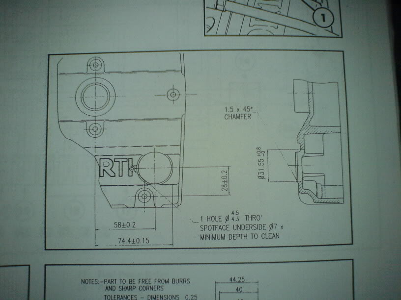
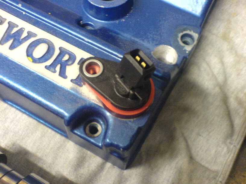
To fit the phase sensor in the cam cover you need to machine the cover to take the sensor holder

Name:  DSC00345.jpg
Views: 1141
Size:  57.5 KB
Name:  DSC00335.jpg
Views: 1419
Size:  94.8 KB

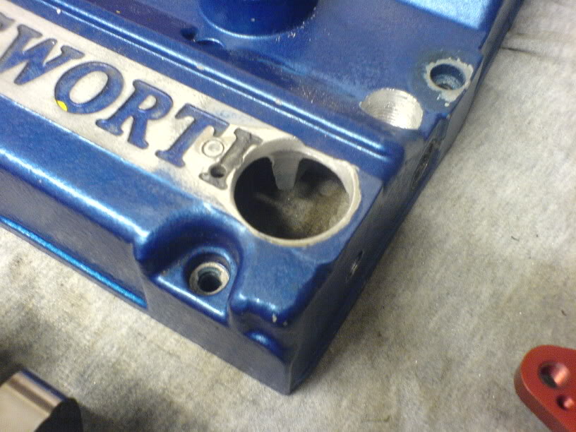
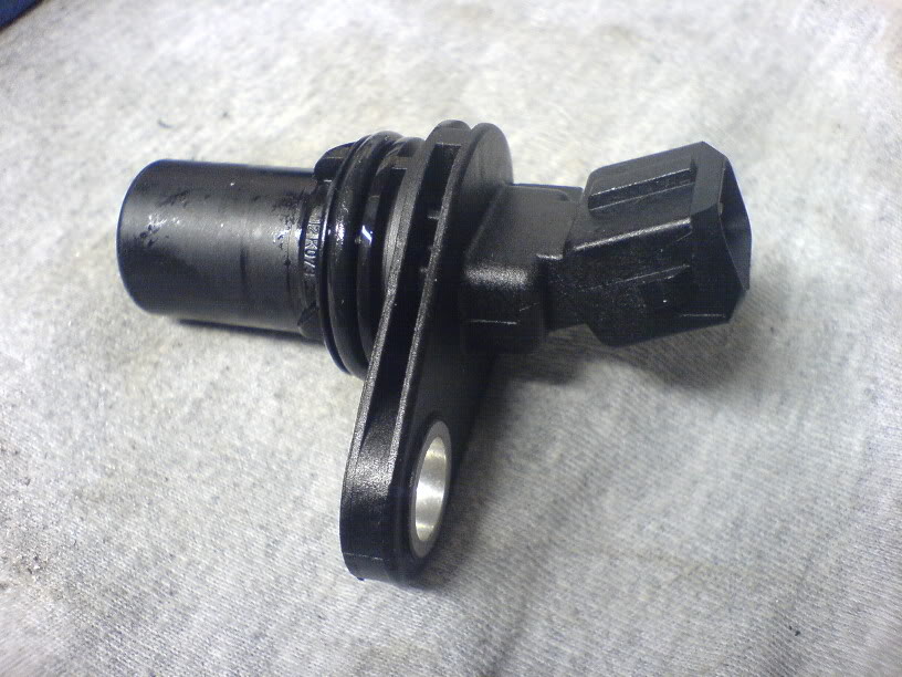
I then got the sensor, holder and phase sensor trigger. Available from Mountune or Zoo.

Name:  DSC00341.jpg
Views: 1343
Size:  93.8 KB
Name:  DSC00339.jpg
Views: 1124
Size:  107.2 KB
Name:  DSC00340.jpg
Views: 1138
Size:  102.8 KB

The sensor and holder fitted to cam cover

Name:  a0e56a7c.jpg
Views: 1505
Size:  82.7 KB

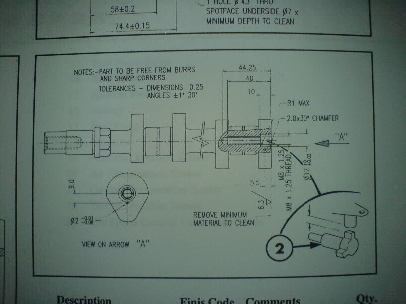
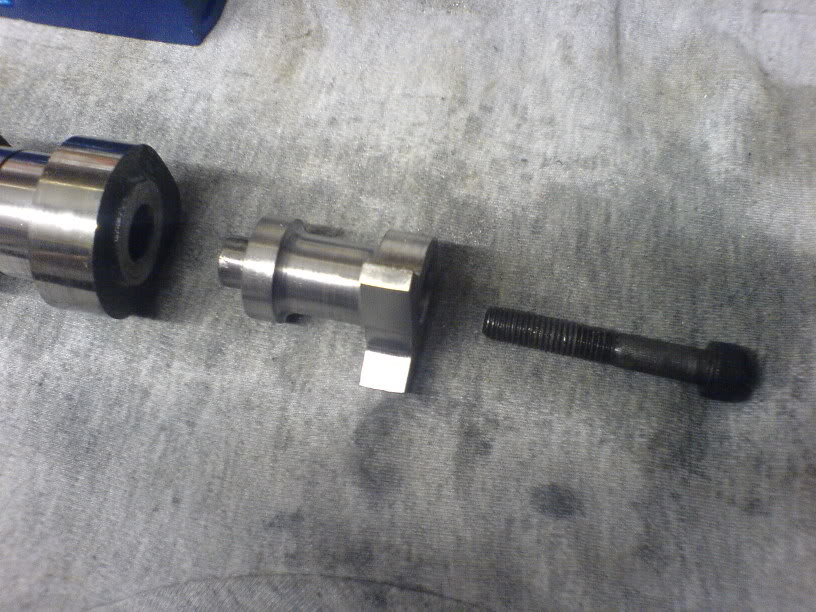
The cam requires machining to take the trigger

Name:  DSC00346.jpg
Views: 1152
Size:  62.6 KB

Thanks to Martin@Reyland for that bit of machining

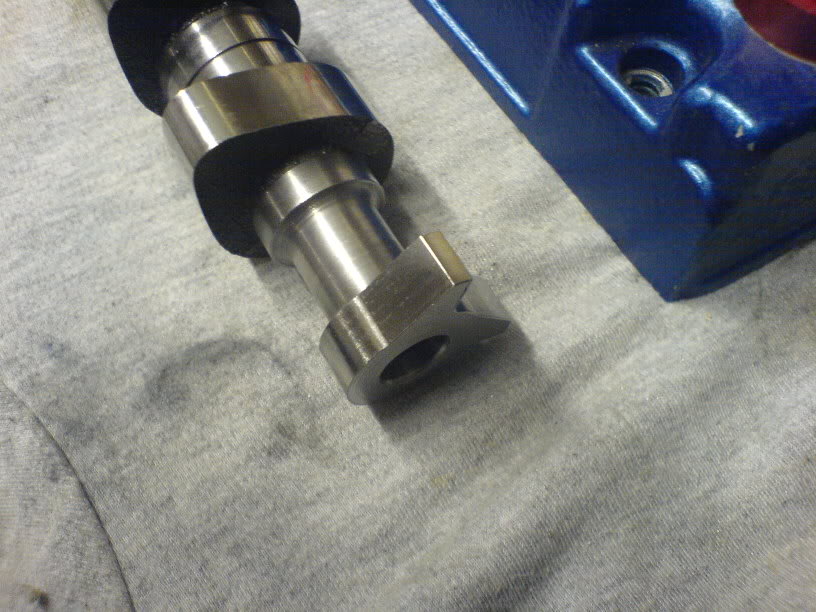
The trigger then bolts into the end of the cam

Name:  DSC00343.jpg
Views: 1377
Size:  98.3 KB
Name:  025132e3.jpg
Views: 1283
Size:  90.4 KB

Next update will be the timing of the phase sensor to the cam and final fitting of the cam and cover.
Reply