FAO Cossie Ecu/engine Wiring loom know it alls ;)
 02-07-2005, 07:16 PM
#1
PassionFord Post Whore!!
Thread Starter

Join Date: May 2003
Location: SE
Posts: 9,226
Likes: 0
Received 0 Likes
on
0 Posts
Been stripping out my old engine loom on my car, ready for my pectel loom... got a few Questions 
What do these pins do on the ECU??
7,
12,
9,
10,
28...
Where does the std ECU take its perm live and IGN live from?
Does the ECU live up the fuel pump relay?
Also does anyone know if I can ditch the carbon canister and purge solonoid thing?...
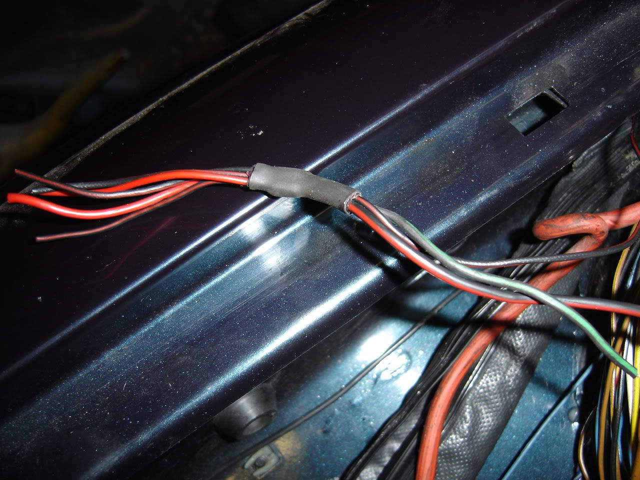
Also on the loom to the ECU 3 wires go to the Lambda sensor obviously, what does the Green/Black wire do??... Because it simly goes to a soldered joint within bulkhead loom, consisting of 5 or 6 wires... being RED and Black/Red.. I tought this would be an IGN live but doesnt appear so I'm guessing the Black/red wires are some kind of switched live wires ??
These... you can see the green black wire from lambda here and the reds went to engine loom, one of the red/blacks went to amal valve plug....
Anyone got a set of wiring diagrams??
What do these pins do on the ECU??
7,
12,
9,
10,
28...
Where does the std ECU take its perm live and IGN live from?
Does the ECU live up the fuel pump relay?
Also does anyone know if I can ditch the carbon canister and purge solonoid thing?...
Also on the loom to the ECU 3 wires go to the Lambda sensor obviously, what does the Green/Black wire do??... Because it simly goes to a soldered joint within bulkhead loom, consisting of 5 or 6 wires... being RED and Black/Red.. I tought this would be an IGN live but doesnt appear so
These... you can see the green black wire from lambda here and the reds went to engine loom, one of the red/blacks went to amal valve plug....
Anyone got a set of wiring diagrams??
 02-07-2005, 07:38 PM
#2
PassionFord Post Whore!!
iTrader: (1)

Join Date: Aug 2004
Location: enfield
Posts: 3,905
Likes: 0
Received 0 Likes
on
0 Posts
28 fuel pump relay
9 blank
10 blank may be main batt main relay
12a/c 4x4
7blank or may be knock sensor
correct me if iam wroung but this is just of the top off my head
9 blank
10 blank may be main batt main relay
12a/c 4x4
7blank or may be knock sensor
correct me if iam wroung but this is just of the top off my head
02-07-2005, 07:45 PM
#3
PassionFord Post Whore!!
Thread Starter
Join Date: May 2003
Location: SE
Posts: 9,226
Likes: 0
Received 0 Likes
on
0 Posts
Cheers mate, Anyone confirm these??
Its P8 ECU by the way..
so you reckon 28 sends a live feed to the pump yeah?? that would kinda make sense..
and 10 may be main battery relay?? whats that then permanent live INTO the ECU??
BTW ALL the pins listed above have wires in them.. if that helps??
Its P8 ECU by the way..
so you reckon 28 sends a live feed to the pump yeah?? that would kinda make sense..
and 10 may be main battery relay?? whats that then permanent live INTO the ECU??
BTW ALL the pins listed above have wires in them.. if that helps??
Trending Topics
02-07-2005, 07:59 PM
#8
PassionFord Post Whore!!
Thread Starter
Join Date: May 2003
Location: SE
Posts: 9,226
Likes: 0
Received 0 Likes
on
0 Posts
Sweet  ... come on Gareth Get online
I'm pretty sure I have done everything by the book , but want to be sure I have sorted all immobilised circuits ok, as obviously all the wires are black oh and this is the first time Ive done this
I'm pretty sure I have done everything by the book , but want to be sure I have sorted all immobilised circuits ok, as obviously all the wires are black oh and this is the first time Ive done this
02-07-2005, 08:11 PM
#10
PassionFord Post Whore!!
Thread Starter
Join Date: May 2003
Location: SE
Posts: 9,226
Likes: 0
Received 0 Likes
on
0 Posts
The immobiliser was attatched to ECU loom, but also went across bulkhead and a couple of wires went into bulkhead grommet to fusebox area, Im fairly sure they were just earths and IGN live, but there was 1 I wasnt entirely sure about, plus I want to be sure now I have all the ECU loom out, I have everything in order for new loom ;')
ALSO
There is a wire which I think comes from speed sensor plug goes through ECU loom grommet and plugs on to another wire in the kickwell.... as this for the ABS?
ALSO
There is a wire which I think comes from speed sensor plug goes through ECU loom grommet and plugs on to another wire in the kickwell.... as this for the ABS?
03-07-2005, 09:36 AM
#12
PassionFord Post Whore!!
here you go
PIN 1 (30-61A) Connection for ignition adjustment BROWN
PIN 1 (30-61B) Earth BROWN
PIN 2 Not Connected
PIN 3 ECU - CRANK SENSOR (31B-72) BROWN/RED
PIN 4 ECU - CRANK SENSOR (1-1A) GREEN/RED
PIN 5 (1-5) - Green / Yellow - Distributor (1-5)
PIN 6 Not Connected
PIN 7 Not Connected
PIN 8 Not Connected
PIN 9 Not Connected
PIN 10 BLUE - PIN85 POWER RELAY
PIN 11 - Manifold AIR TEMP SENSOR (31B-11C) BROWN/GREEN
PIN 11 ECU - MAP SENSOR (31B-11D)BROWN/GREEN (SHIELDED)
PIN 11 ECU - COOLANT TEMP SENSOR (31B-11C) BROWN/GREEN
PIN 11 ECU - THROTTLE POSITION SENSOR (31B-11A) BROWN/GREEN
PIN 12 (31B-35) BROWN/GREEN
PIN 13 Connection for ignition adjustment (15-10) BLACK/BLUE
PIN 14 Connection for ignition adjustment (15-9) BLACK/GREEN
PIN 15 ECU - MAP SENSOR (54-46) BLACK/RED (SHIELED)
PIN 16 ECU - AMAL VALVE (31B-68A)BROWN/GREEN
PIN 17 ECU - THROTTLE POSITION SENSOR (54-45) BLACK/YELLOW
PIN 18 ECU - Fuel Injector CYC 4 - (31B-43D) BROWN/WHITE
PIN 19 (31-61B) Earth BROWN
PIN 20 (30-42) RED PIN 87 POWER RELAY
PIN 21 Not Connected
PIN 22 Not Connected
PIN 23 (15-13) - Black / Red - Distributor (15-13)
PIN 24 IGNITION AMP (15-C)BLACK/RED
PIN 25 IGNITION AMP (15A)BLACK
PIN 26 Not Connected
PIN 27 Not Connected
PIN 28 BLUE/BLACK - PIN85 FUEL PUMP RELAY
PIN 29 ECU - COOLANT TEMP SENSOR (54-44) BLACK
PIN 30 ECU - MAP SENSOR (30-45)RED (SHIELDED)
PIN 30 ECU - THROTTLE POSITION SENSOR (30-45A) RED
PIN 31 - Manifold AIR TEMP SENSOR (30-46) RED
PIN 32 ECU - Fuel Injector CYC 2 - (31B-43B) BROWN/GREEN
PIN 33 ECU - Fuel Injector CYC 3 - (31B-43C) BROWN/BLACK
PIN 34 ECU IDLE SPEED CONTROL VALVE (31B-68CRG) GREEN/YELLOW
PIN 35 ECU - Fuel Injector CYC 1 - (31B-43A) BROWN/YELLOW
got from another link on p/f 2 months ago.
 03-07-2005, 10:36 AM
#23
BANNED
BANNED
iTrader: (1)

Join Date: Jul 2003
Location: Wiltshire
Posts: 12,483
Likes: 0
Received 0 Likes
on
0 Posts
Confirmation of a P8 ecu pin functions for you.....
1 POWER GROUND
2 LAMBDA SENSOR INPUT
3 CRANK SENSOR GROUND
4 CRANK SENSOR INPUT
5 PHASE SENSOR GROUND
6 KNOCK SENSOR GROUND
7 CANNISTER PURGE VALVE
8 DIAGNOSTIC SOCKET
9 LINK TO PIN 30
10 POWER RELAY
11 SENSORS GROUND
12 AIR CON CONTROL (IF FITTED)
13 OCTANE ADJUST PLUG
14 OCTANE ADJUST PLUG
15 MAP SENSOR INPUT
16 AMAL VALVE
17 THROTTLE POSITION SENSOR
18 INJECTOR 4
19 POWER GROUND
20 12 VOLTS POSITIVE SUPPLY
21 NOT USED
22 KNOCK SENSOR INPUT
23 PHASE SENSOR INPUT
24 IGNITION TRIGGER GROUND
25 IGNITION TRIGGER OUTPUT
26 NOT USED
27 DIAGNOSTIC SOCKET
28 FUEL PUMP RELAY
29 COOLANT SENSOR
30 SENSOR POSITIVE SUPPLY (5 VOLTS)
31 CHARGE AIR SENSOR
32 INJECTOR 2
33 INJECTOR 3
34 IDLE SPEED VALVE
35 INJECTOR 1
03-07-2005, 10:43 AM
#24
PassionFord Post Whore!!
Thread Starter
Join Date: May 2003
Location: SE
Posts: 9,226
Likes: 0
Received 0 Likes
on
0 Posts
Cheers Simon,
Pin 20, thats a perm live yeah?
28, that a switched earth switched on by ECU?
Pin 10 Is that a switched earth by ECU also?
Any Ideas on the green / black wire in the pic, which comes from the Lamda? ... I'm trying to confirm what that clump of wires is, ie is it a switched live when ECU is switched on etc, or is it lived up from Pump relay? as it doesnt live up when IGN on ...
any wiring diagrams at all??
I'm ofline shortly, but if anyone has some my email is damianvennard@aol.com
Cheers
03-07-2005, 10:45 AM
#25
10K+ Poster!!
iTrader: (1)

Join Date: May 2003
Location: Lancashire
Posts: 12,748
Likes: 0
Received 0 Likes
on
0 Posts
Ok, this is correct as per Ford wiring diagram for the Escort Cossie large turbo....
Pin 1 - Earth (brown)
Pin 19 - Earth (brown)
Pin 2 - Lambda sensor (brown/white)
Pin 20 - Power (red)
Pin 3 - Crank position sensor (brown/yellow)
Pin 21 - Not used
Pin 4 - Crank position sensor (green/red)
Pin 22 - Knock sensor (blue/yellow in shielded cable)
Pin 5 - Distributor phase sensor (green/yellow)
Pin 23 - Distributor phase sensor (black/red)
Pin 6 - Knock sensor (black/yellow with brown earth from shield)
Pin 24 - Pin 3 Ignition module (Black)
Pin 7 - Canister purge valve (brown/white)
Pin 25 - Pin 6 Ignition module (black)
Pin 8 - Electronic control loom (blue/white)
Pin 26 - Not used
Pin 9 - Connected throttle pot wire (Pin 30 red) (white)
Pin 27 - Electronic control loom (blue/yellow)
Pin 10 - EFI power relay pin 85 (relay 8) in fuse box (plug M3BB at fuse box) (blue/yellow)
Pin 28 - Fuel pump relay pin 85 (relay 9) in fuse box (plug M5B at fuse box) (blue/gree)
Pin 11 - Map sensor (shielded) and link to common connection* (brown/green)
Pin 29 - Coolant temp sensor (black/green)
Pin 12 - Not used
Pin 30 - MAP sensor and throttle pot sensor (red)
Pin 13 - Octane adjust (black)
Pin 31 - Air charge temp sensor (red/green)
Pin 14 - Octane adjust (black)
Pin 32 - Injector 2 (brown/black)
Pin 15 - MAP sensor (black/red)
Pin 33 - Injector 3 (brown/black)
Pin 16 - Boost valve (brown/yellow)
Pin 34 - Idle speed control valve (brown/yellow)
Pin 17 - Throttle pot sensor (black/red)
Pin 35 - Injector 1 (brown/black)
Pin 18 -Injector 4 (brown/black)
*Pin 11 (brown/green) connects to the following....
Electronic control loom
Coolant temp sensor
Throttle pot sensor
Aircharge temp sensor
03-07-2005, 10:51 AM
#28
BANNED
BANNED
iTrader: (1)
Join Date: Jul 2003
Location: Wiltshire
Posts: 12,483
Likes: 0
Received 0 Likes
on
0 Posts
Pin 20 is a SWITCHED ignition live NOT a permanent live.
Pin 10 is the sensor earth and must NOT be used for anything else.
Pin 28 is an earth switched output for the fuel pump relay.
Pin 10 is the sensor earth and must NOT be used for anything else.
Pin 28 is an earth switched output for the fuel pump relay.
03-07-2005, 10:52 AM
#29
10K+ Poster!!
iTrader: (1)
Join Date: May 2003
Location: Lancashire
Posts: 12,748
Likes: 0
Received 0 Likes
on
0 Posts
Black/green should be live with ignition as it comes from a common connection to supply power to the injectors, Pin 20 of the ECU, Idle speed control valve, Canister purge valve, and then the lambda sensor
03-07-2005, 11:00 AM
#30
PassionFord Post Whore!!
Thread Starter
Join Date: May 2003
Location: SE
Posts: 9,226
Likes: 0
Received 0 Likes
on
0 Posts
Thats what I thought Daz, but it isnt.....
Would you suggest as, pins 10 and 28 are not earthed, this would be why they arent live?
So how does the ECU get a Permanent live then? Obviously I imagine the new one will be direct to battery but Im interested to find out how the old one gets it
Would you suggest as, pins 10 and 28 are not earthed, this would be why they arent live?
So how does the ECU get a Permanent live then? Obviously I imagine the new one will be direct to battery but Im interested to find out how the old one gets it
03-07-2005, 11:03 AM
#31
PassionFord Post Whore!!
Thread Starter
Join Date: May 2003
Location: SE
Posts: 9,226
Likes: 0
Received 0 Likes
on
0 Posts
what I will do is earth the wires which should go to pin
10 and 28, this should give me a pump live and hopefully IGN live on the wires in the pic...
10 and 28, this should give me a pump live and hopefully IGN live on the wires in the pic...
03-07-2005, 11:04 AM
#32
BANNED
BANNED
iTrader: (1)
Join Date: Jul 2003
Location: Wiltshire
Posts: 12,483
Likes: 0
Received 0 Likes
on
0 Posts
The ecu does NOT have a permanent live !!!!!! 
When the ignition is on and the ecu is fitted,
the ecu links link 1 and 10 internally, this then in turns operates a relay in the fuse box which puts power onto pin 20 !!!!
When the ignition is on and the ecu is fitted,
the ecu links link 1 and 10 internally, this then in turns operates a relay in the fuse box which puts power onto pin 20 !!!!
03-07-2005, 11:06 AM
#33
PassionFord Post Whore!!
Thread Starter
Join Date: May 2003
Location: SE
Posts: 9,226
Likes: 0
Received 0 Likes
on
0 Posts
Oh right!! So how does it remember stuff?? I mean its suggested disconnecting the battery or removing ECU resets a number of codes etc If there is no perm live, how does it know whether battery on or off ?? How does that work then?
03-07-2005, 11:08 AM
#34
BANNED
BANNED
iTrader: (1)
Join Date: Jul 2003
Location: Wiltshire
Posts: 12,483
Likes: 0
Received 0 Likes
on
0 Posts
It has non volatile flash memory to remember lambda learning tables !!!
I.E. memory that does NOT require power to remember!
The same way that memory cards work now !
I.E. memory that does NOT require power to remember!
The same way that memory cards work now !
04-07-2005, 08:17 PM
#37
PassionFord Post Whore!!
Thread Starter
Join Date: May 2003
Location: SE
Posts: 9,226
Likes: 0
Received 0 Likes
on
0 Posts
Sorted it... Gave the 2 wires I mentioned above an earth, which in turn gave me a fuel pump live and made the wires in the pic above live up too 
Cheers, all I wanted to do was put my mind at rest and with the help of you guys I think I've done that... Time will tel thoiugh, once I get my new loom in
Cheers, all I wanted to do was put my mind at rest and with the help of you guys I think I've done that

Thread
Thread Starter
Forum
Replies
Last Post
kosienutter
General Car Related Discussion.
31
22-08-2015 09:55 AM
salsheikh
Alloy wheels and ICE for sale
0
30-07-2015 08:45 PM