Pectel 2 Management, what pulley? 2wd Cosworth
 13-08-2013, 11:53 AM
#1
15000
Thread Starter

Join Date: Oct 2011
Location: Scotland now
Posts: 20
Likes: 0
Received 0 Likes
on
0 Posts
Hello
i have bought a pectel 2 ecu injectors and loom for my 2wd cosworth but didnt realise i required a new crank pulley. what crank pulley should i be using with this set up?
thankyou
i have bought a pectel 2 ecu injectors and loom for my 2wd cosworth but didnt realise i required a new crank pulley. what crank pulley should i be using with this set up?
thankyou


 15-08-2013, 02:53 PM
#5
15000
Thread Starter
Join Date: Oct 2011
Location: Scotland now
Posts: 20
Likes: 0
Received 0 Likes
on
0 Posts
thanks for the info, i managed to get the pulley from the guy i bought the ecu etc from but my crank sensor does not line up with the new pulley. is there a different bracket for this and where can i get one? i think its the 36-1 pulley. many thanks
15-08-2013, 02:58 PM
#6
Hi mike, you have to modify the crank sensor bracket, we generally do this on the milling machine but I'm sure you could slot the holes easy enough.
Be very careful when you get to mapping it as dependant on the pulley you will need to offset the global ignition adder to suit
Jim
Be very careful when you get to mapping it as dependant on the pulley you will need to offset the global ignition adder to suit
Jim
15-08-2013, 04:53 PM
#7
15000
Thread Starter
Join Date: Oct 2011
Location: Scotland now
Posts: 20
Likes: 0
Received 0 Likes
on
0 Posts
hi jim, thanks for the reply.
the ecu, injectors, loom and pulley all came from a car that you guys had set up and supplied the parts for. i was going to take the car down to you guys next year for a setup. what is the global ignition adder? many thanks
the ecu, injectors, loom and pulley all came from a car that you guys had set up and supplied the parts for. i was going to take the car down to you guys next year for a setup. what is the global ignition adder? many thanks
Trending Topics
15-08-2013, 05:18 PM
#8
You can do it that way Jim but the global ign adder isn't designed for that purpose is it? Surely you should go in to 'software set up' and then click on 'crank sensor offset' and set it there, then you can use the global ign adder for the purpose its designed, also that way what you see on the ign table is what you've got (plus or minus any corrections).
Last edited by Martin-Hadland; 15-08-2013 at 05:42 PM.
15-08-2013, 08:23 PM
#9
You can do it that way Jim but the global ign adder isn't designed for that purpose is it? Surely you should go in to 'software set up' and then click on 'crank sensor offset' and set it there, then you can use the global ign adder for the purpose its designed, also that way what you see on the ign table is what you've got (plus or minus any corrections).
Not to mention what you see in the ignition map IS what the engine is getting. The global adder is just sorting the "wrongly" positioned cranksensor/missing tooth.
Last edited by J1mbo; 15-08-2013 at 08:27 PM.
15-08-2013, 08:26 PM
#10
Speak to the person mapping your car would be my first bit of advise. As above each person will have different opinions.
But global ignition adder is as it says, you can add or minus ignition from the whole map, ie move the crank sensor and you can put it right using this function.
15-08-2013, 08:34 PM
#11
PassionFord Post Troll
All off the shelf parts , fit and forget .
15-08-2013, 09:01 PM
#12
15000
Thread Starter
Join Date: Oct 2011
Location: Scotland now
Posts: 20
Likes: 0
Received 0 Likes
on
0 Posts
Thanks for all the help.
So to get the car running what should I set the crank sensor at? Will it be safe to drive? My cars the same spec as the car it came off but obviously will need set up. Thanks
So to get the car running what should I set the crank sensor at? Will it be safe to drive? My cars the same spec as the car it came off but obviously will need set up. Thanks
16-08-2013, 07:44 AM
#13
Thinking about it I agree that the ign table would read correctly, but the dash board display of total ign wouldn't read correct would it? Not that it would really matter but if you had a monitor wired up that displayed total ign surely that would read incorrectly by the amount set in the global adder? wouldn't that also make the reading given when checking crank position with a timing light incorrect?
I would use the global adder (or subtracter) for making global adjustments for safety or testing and I would know that the start figure would be zero, you would always have to remember what the initial figure was and add or subtract from that.
I'm not having a pop, I'm just saying that the ecu has the facility so why not use it, once set its tucked away and everything reads right
The other thing I forgot to mention is that I'm sure T2 only allows a global adjustment/crank sensor offset of + or - 20 deg which would mean moving the sensor or missing tooth location on an application that has a greater misalignment.
Last edited by Martin-Hadland; 16-08-2013 at 08:13 AM.
16-08-2013, 08:01 AM
#14
Mark up true TDC on the crank pulley against a pointer with a white paint pen, get the ign map up on screen and run the car at something like 1500 rpm(or a little higher) so that you can take a steady reading with a timing light, with the ign map open you will get a dash board on the right that shows ign corrections, one of them shows total ign. Compare that figure to what your timing light says and adjust the crank offset to suit. Be aware that because its wasted spark a standard timing light will need to read double what the T2 says total ign is, so if total ign shown on the screen is 20 you'd need to see 40 on the light.
To access the crank offset you need to:
Press M on the keyboard which will bring up some mapping options
Click on 'software setup'
Then click on 'Engine mode and crank sync'
Then click on 'crank sensor offset' and adjust to suit.
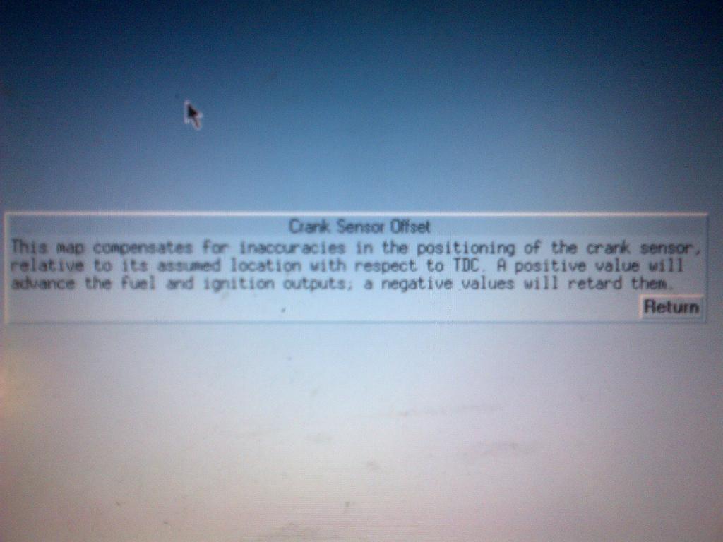
Pressing F1 on the keyboard sometimes brings up a help screen, below is what you get for crank sensor offset:
 16-08-2013, 12:40 PM
#15
I can't see a problem with the way you've said to do it Jim but as the ecu has the facility to sort this then I can't see why you'd do it that way?
Thinking about it I agree that the ign table would read correctly, but the dash board display of total ign wouldn't read correct would it? Not that it would really matter but if you had a monitor wired up that displayed total ign surely that would read incorrectly by the amount set in the global adder? wouldn't that also make the reading given when checking crank position with a timing light incorrect?
I would use the global adder (or subtracter) for making global adjustments for safety or testing and I would know that the start figure would be zero, you would always have to remember what the initial figure was and add or subtract from that.
I'm not having a pop, I'm just saying that the ecu has the facility so why not use it, once set its tucked away and everything reads right
The other thing I forgot to mention is that I'm sure T2 only allows a global adjustment/crank sensor offset of + or - 20 deg which would mean moving the sensor or missing tooth location on an application that has a greater misalignment.
We use the ignition map should we wish to change anything I can't say I've ever needed to use global for anything other than offsetting cranksensors

MikeR - if your running the same pulley and set up as off the engine you bought it you will be safe to start it up as the map will be set correctly
16-08-2013, 02:21 PM
#17
15000
Thread Starter
Join Date: Oct 2011
Location: Scotland now
Posts: 20
Likes: 0
Received 0 Likes
on
0 Posts
thanks for all the information and help guys.
the only part i didnt get was the crank sensor bracket so i have modified the one i have to the crank sensor sits where the 36 triggers are if that makes sense. is this the right way to do it? and should i gap it between the sensor and there?
thanks again
the only part i didnt get was the crank sensor bracket so i have modified the one i have to the crank sensor sits where the 36 triggers are if that makes sense. is this the right way to do it? and should i gap it between the sensor and there?
thanks again
16-08-2013, 02:35 PM
#18
thanks for all the information and help guys.
the only part i didnt get was the crank sensor bracket so i have modified the one i have to the crank sensor sits where the 36 triggers are if that makes sense. is this the right way to do it? and should i gap it between the sensor and there?
thanks again
the only part i didnt get was the crank sensor bracket so i have modified the one i have to the crank sensor sits where the 36 triggers are if that makes sense. is this the right way to do it? and should i gap it between the sensor and there?
thanks again
Iirc you should just have to slot the crank sensor hole to bring the sensor inline with the wheel then tap it for new bolts to hold the sensor in
16-08-2013, 02:59 PM
#19
15000
Thread Starter
Join Date: Oct 2011
Location: Scotland now
Posts: 20
Likes: 0
Received 0 Likes
on
0 Posts
Perfect thanks for the info. What should the gap be?

Thread
Thread Starter
Forum
Replies
Last Post
Focosmitch
Ford RS Cosworth Parts for Sale
36
09-10-2015 07:38 PM
FlashRS
Ford RS Cosworth Parts for Sale
13
31-08-2015 06:02 PM