
Cosworth ECU / loom plug - Pin identification?
 20-02-2005 | 11:43 AM
#1

Thread Starter
BANNED
Joined: May 2003
Posts: 23,032
Likes: 2
From: Mongsville, wiping Jimbo.'s spastic arse.
30 odd pins on the ECU connecting it to the loom
does anyone have a breakdown for what they are all for?
i have a few from the SECS manual but thats it
cheers
Dave
does anyone have a breakdown for what they are all for?
i have a few from the SECS manual but thats it
cheers
Dave

 20-02-2005 | 12:11 PM
#4

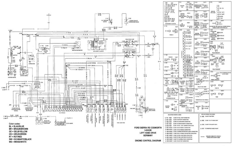
Here is a list of ecu connections.
Not all pins are used on all versions of ecu but gives a general idea.
1 POWER GROUND
2 LAMBDA SENSOR INPUT
3 CRANK SENSOR GROUND
4 CRANK SENSOR INPUT
5 PHASE SENSOR GROUND
6 KNOCK SENSOR GROUND
7 PURGE VALVE
8 DIAGNOSTIC SOCKET
9 VREF MONITOR
10 POWER RELAY EARTH
11 VREF NEGATIVE
12 WARNING LAMP OUTPUT
13 OCTANE ADJUST
14 OCTANE ADJUST
15 MAP SENSOR INPUT
16 BOOST VALVE
17 THROTTLE POSITION
18 INJECTOR 4
19 POWER GROUND
20 POSITIVE SUPPLY
21 NOT USED
22 KNOCK SENSOR INPUT
23 PHASE SENSOR INPUT
24 IGNITION TRIGGER GROUND
25 IGNITION TRIGGER OUTPUT
26 SPARE
27 DIAGNOSTIC SOCKET
28 FUEL PUMP RELAY
29 COOLANT SENSOR
30 VREF POSITIVE
31 CHARGE AIR SENSOR
32 INJECTOR 2
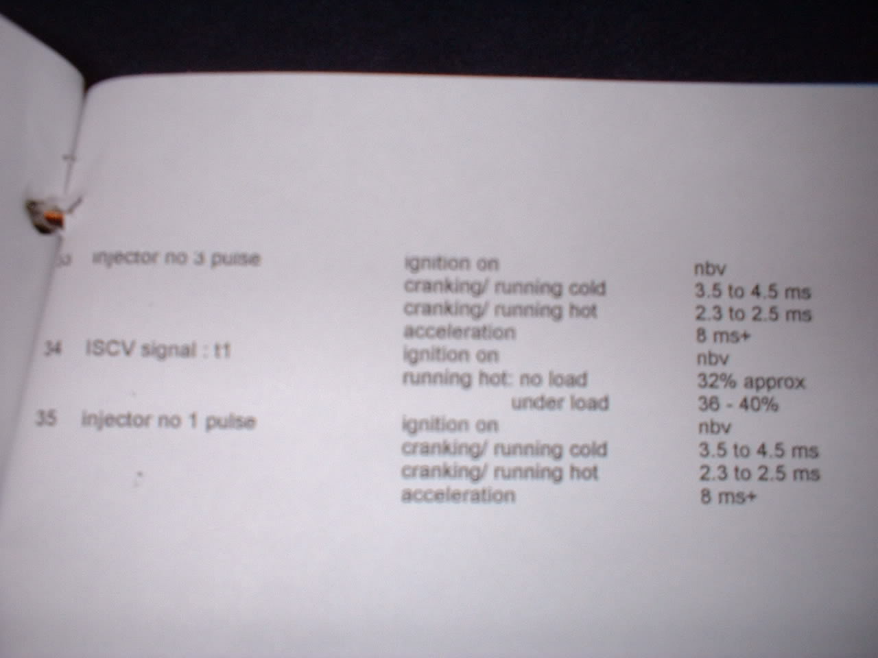
33 INJECTOR 3
34 IDLE SPEED VALVE
35 INJECTOR 1
Not all pins are used on all versions of ecu but gives a general idea.
1 POWER GROUND
2 LAMBDA SENSOR INPUT
3 CRANK SENSOR GROUND
4 CRANK SENSOR INPUT
5 PHASE SENSOR GROUND
6 KNOCK SENSOR GROUND
7 PURGE VALVE
8 DIAGNOSTIC SOCKET
9 VREF MONITOR
10 POWER RELAY EARTH
11 VREF NEGATIVE
12 WARNING LAMP OUTPUT
13 OCTANE ADJUST
14 OCTANE ADJUST
15 MAP SENSOR INPUT
16 BOOST VALVE
17 THROTTLE POSITION
18 INJECTOR 4
19 POWER GROUND
20 POSITIVE SUPPLY
21 NOT USED
22 KNOCK SENSOR INPUT
23 PHASE SENSOR INPUT
24 IGNITION TRIGGER GROUND
25 IGNITION TRIGGER OUTPUT
26 SPARE
27 DIAGNOSTIC SOCKET
28 FUEL PUMP RELAY
29 COOLANT SENSOR
30 VREF POSITIVE
31 CHARGE AIR SENSOR
32 INJECTOR 2
33 INJECTOR 3
34 IDLE SPEED VALVE
35 INJECTOR 1
20-02-2005 | 12:12 PM
#5
Thread Starter
BANNED
Joined: May 2003
Posts: 23,032
Likes: 2
From: Mongsville, wiping Jimbo.'s spastic arse.
cheers scruff, i need a p8 diagram
Rich, i dont mate BUT ive found this on here can you confirm them to yours?
cheers mate
PIN 1 (30-61A) Connection for ignition adjustment BROWN
PIN 1 (30-61B) Earth BROWN
PIN 2 Not Connected
PIN 3 ECU - CRANK SENSOR (31B-72) BROWN/RED
PIN 4 ECU - CRANK SENSOR (1-1A) GREEN/RED
PIN 5 (1-5) - Green / Yellow - Distributor (1-5)
PIN 6 Not Connected
PIN 7 Not Connected
PIN 8 Not Connected
PIN 9 Not Connected
PIN 10 BLUE - PIN85 POWER RELAY
PIN 11 - Manifold AIR TEMP SENSOR (31B-11C) BROWN/GREEN
PIN 11 ECU - MAP SENSOR (31B-11D)BROWN/GREEN (SHIELDED)
PIN 11 ECU - COOLANT TEMP SENSOR (31B-11C) BROWN/GREEN
PIN 11 ECU - THROTTLE POSITION SENSOR (31B-11A) BROWN/GREEN
PIN 12 (31B-35) BROWN/GREEN
PIN 13 Connection for ignition adjustment (15-10) BLACK/BLUE
PIN 14 Connection for ignition adjustment (15-9) BLACK/GREEN
PIN 15 ECU - MAP SENSOR (54-46) BLACK/RED (SHIELED)
PIN 16 ECU - AMAL VALVE (31B-68A)BROWN/GREEN
PIN 17 ECU - THROTTLE POSITION SENSOR (54-45) BLACK/YELLOW
PIN 18 ECU - Fuel Injector CYC 4 - (31B-43D) BROWN/WHITE
PIN 19 (31-61B) Earth BROWN
PIN 20 (30-42) RED PIN 87 POWER RELAY
PIN 21 Not Connected
PIN 22 Not Connected
PIN 23 (15-13) - Black / Red - Distributor (15-13)
PIN 24 IGNITION AMP (15-C)BLACK/RED
PIN 25 IGNITION AMP (15A)BLACK
PIN 26 Not Connected
PIN 27 Not Connected
PIN 28 BLUE/BLACK - PIN85 FUEL PUMP RELAY
PIN 29 ECU - COOLANT TEMP SENSOR (54-44) BLACK
PIN 30 ECU - MAP SENSOR (30-45)RED (SHIELDED)
PIN 30 ECU - THROTTLE POSITION SENSOR (30-45A) RED
PIN 31 - Manifold AIR TEMP SENSOR (30-46) RED
PIN 32 ECU - Fuel Injector CYC 2 - (31B-43B) BROWN/GREEN
PIN 33 ECU - Fuel Injector CYC 3 - (31B-43C) BROWN/BLACK
PIN 34 ECU IDLE SPEED CONTROL VALVE (31B-68CRG) GREEN/YELLOW
PIN 35 ECU - Fuel Injector CYC 1 - (31B-43A) BROWN/YELLOW)
Trending Topics
 20-02-2005 | 12:24 PM
#10
Thread Starter
BANNED
Joined: May 2003
Posts: 23,032
Likes: 2
From: Mongsville, wiping Jimbo.'s spastic arse.
cheers simon.. hey you know what you did for maria?
i dont suppose you would come to mine to sort my poxy esc cos would you? obviously on a customer basis so I would drizzle you in cash

i dont suppose you would come to mine to sort my poxy esc cos would you? obviously on a customer basis so I would drizzle you in cash
20-02-2005 | 12:26 PM
#14
Thread Starter
BANNED
Joined: May 2003
Posts: 23,032
Likes: 2
From: Mongsville, wiping Jimbo.'s spastic arse.
Originally Posted by SECS
DaveEscos, I did ask on your other thread where you were ?
im by the dartford tunnel on the M25.
 20-02-2005 | 12:37 PM
#18
Thread Starter
BANNED
Joined: May 2003
Posts: 23,032
Likes: 2
From: Mongsville, wiping Jimbo.'s spastic arse.
that would be superb and much appreciated. 
basically last thing i saw was the secs monitor flicker off when i pulled up, then the engine wouldnt restart and the sec monitor was blank, not even lit up BUT i had ignition and fuel pump priming
down to halfords I go to get said meter !
basically last thing i saw was the secs monitor flicker off when i pulled up, then the engine wouldnt restart and the sec monitor was blank, not even lit up BUT i had ignition and fuel pump priming
down to halfords I go to get said meter !
20-02-2005 | 01:06 PM
#22
BASIC FAULT FINDING GUIDE FOR COSSIE ECUS
NOTES:
Some of these results can be affected by an alarm system or imobilizer.
I have assumed the car has a 2.5 bar/3.0 bar map sensor.
If SECS monitor is fitted, unplug it !
(A faulty monitor or incorrectly fitted can cause engine not to run)
1) Ensure ignition is OFF.
2) Remove rear of ecu plug cover and insert plug back into ecu.
3) Turn ignition back on (do not start engine)
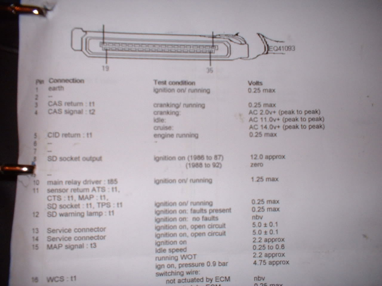
4) MAIN POWER CHECK: Check for DC voltage of at least 11.5 volts between ecu pins 19 and 20.
5) REFERENCE CHECK: Check for DC voltage of around 4.8 to 5.2 volts between pins 11 and 30.
6) MAP SENSOR CHECK: Check for DC voltage of around 1.8 to 2.5 volts between pins 11 and 15.
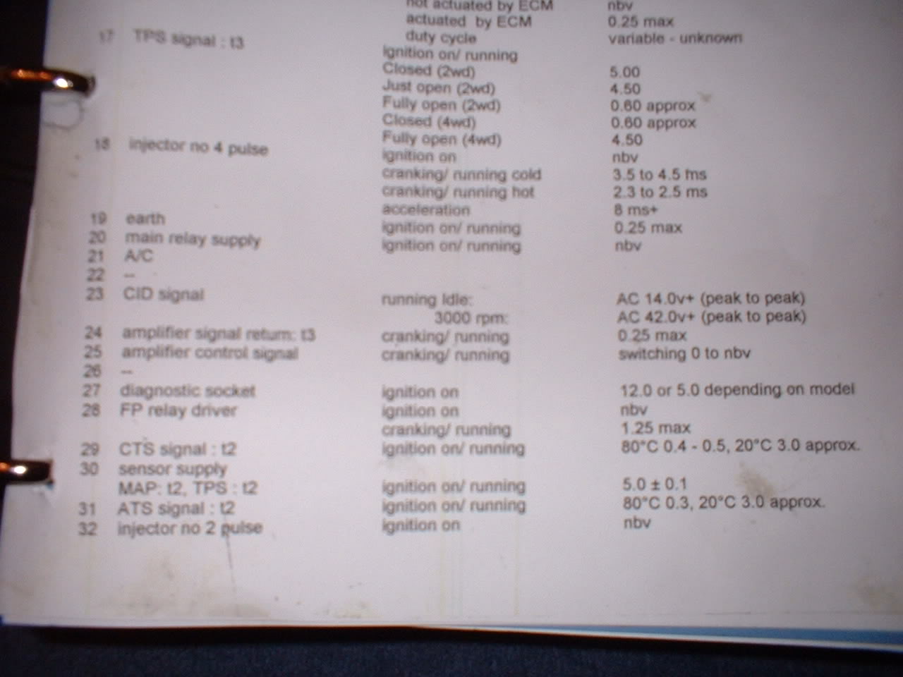
7) 4x4 THROTTLE CLOSED: Check for DC voltage less than 0.5 volts between pins 11 and 17.
2WD: Check for DC voltage greater than 4.5 volts between pins 11 and 17.
8) 4x4: THROTTLE FULLY OPEN: Check for DC voltage greater than 4.5 volts between pins 11 and 17.
2WD: check for DC voltage less than 0.5 volts between pins 11 and 17.
9) Turn ignition off, unlpug ecu, turn ignition back on (dont forget imobilizer if fitted)
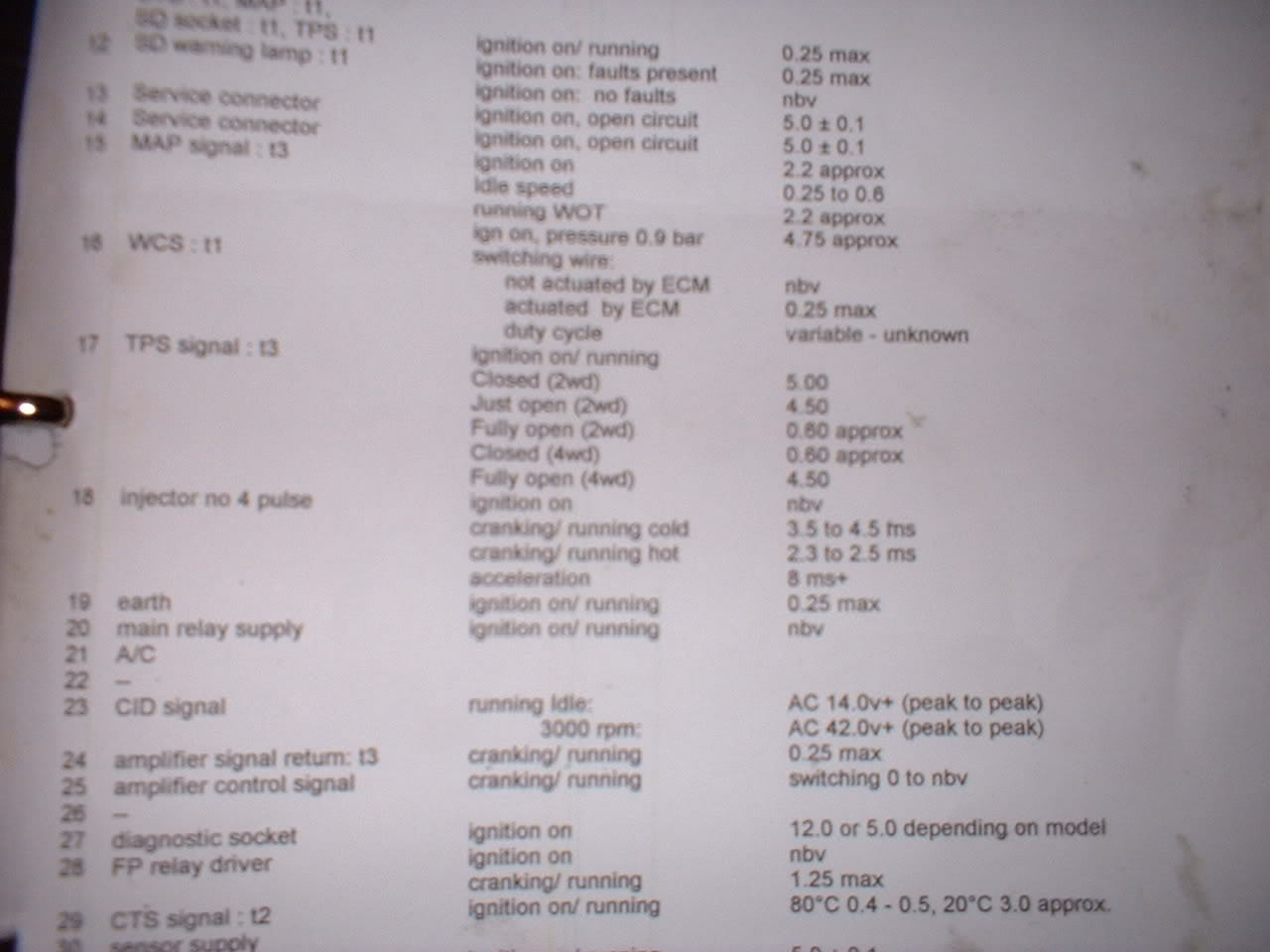
10) CRANK SENSOR: Check resistance between pins 3 and 4 between 300 and 1200 ohms.
11) CRANK SENSOR: Check AC voltage on pins 3 and 4 while cranking engine.
Should be at least 2 volts.
11) PHASE SENSOR: Check resistance between pins 5 and 23 between 300 and 1200 ohms.
12) PHASE SENSOR: Check AC voltage on pins 5 and 23 while cranking engine.
Should be at least 1.5 - 2 volts.
12) INJECTOR: Check resistance from pins 18 to 20 should be 2 to 5 ohms.
13) INJECTOR: Check resistance from pins 35 to 20 should be 2 to 5 ohms.
14) INJECTOR: Check resistance from pins 33 to 20 should be 2 to 5 ohms.
15) INJECTOR: Check resistance from pins 32 to 20 should be 2 to 5 ohms.
NOTE: INJECTOR TESTS MAY NEED MAIN RELAY ENERGISED ON L1 and L6 ecus (link pins 1 and 10 first)
16) IGNITION TRIGGER: Read voltage between pins 24 and 25, should be at least 4.5 volts.
17) IGNITION TEST: BEWARE DANGEROUS VOLTAGES ON PLUG/COIL LEADS.
Quickly link pins 24 and 25 on and off this will FIRE the ignition coil.
Rotate dizzi by moving car in gear to point rotor arm at one plug lead
and remove spark plug (earthing it on chassis or engine) to see spark.
(Dont touch it or you will fry)
Try for each plug in turn.
Or remove king lead at dizzi and place end within 1 centimetre of earth
to see a big spark.
18) Place a temporary wire link from pin 1 to pin 10. (energises ecu power relay)
You should hear a click.
19) Quickly link pins 19 to 28 to test fuel pump runs.
20) COOLANT TEMP: Check resistance pins 29 and 11 for 800 ohms to 5000 ohms (depends on temp)
21) CHARGE TEMP: Check resistance pins 31 and 11 for 800 ohms to 5000 ohms (depends on temp)
These are only basic tests but will find 99% of faults
NOTES:
Some of these results can be affected by an alarm system or imobilizer.
I have assumed the car has a 2.5 bar/3.0 bar map sensor.
If SECS monitor is fitted, unplug it !
(A faulty monitor or incorrectly fitted can cause engine not to run)
1) Ensure ignition is OFF.
2) Remove rear of ecu plug cover and insert plug back into ecu.
3) Turn ignition back on (do not start engine)
4) MAIN POWER CHECK: Check for DC voltage of at least 11.5 volts between ecu pins 19 and 20.
5) REFERENCE CHECK: Check for DC voltage of around 4.8 to 5.2 volts between pins 11 and 30.
6) MAP SENSOR CHECK: Check for DC voltage of around 1.8 to 2.5 volts between pins 11 and 15.
7) 4x4 THROTTLE CLOSED: Check for DC voltage less than 0.5 volts between pins 11 and 17.
2WD: Check for DC voltage greater than 4.5 volts between pins 11 and 17.
8) 4x4: THROTTLE FULLY OPEN: Check for DC voltage greater than 4.5 volts between pins 11 and 17.
2WD: check for DC voltage less than 0.5 volts between pins 11 and 17.
9) Turn ignition off, unlpug ecu, turn ignition back on (dont forget imobilizer if fitted)
10) CRANK SENSOR: Check resistance between pins 3 and 4 between 300 and 1200 ohms.
11) CRANK SENSOR: Check AC voltage on pins 3 and 4 while cranking engine.
Should be at least 2 volts.
11) PHASE SENSOR: Check resistance between pins 5 and 23 between 300 and 1200 ohms.
12) PHASE SENSOR: Check AC voltage on pins 5 and 23 while cranking engine.
Should be at least 1.5 - 2 volts.
12) INJECTOR: Check resistance from pins 18 to 20 should be 2 to 5 ohms.
13) INJECTOR: Check resistance from pins 35 to 20 should be 2 to 5 ohms.
14) INJECTOR: Check resistance from pins 33 to 20 should be 2 to 5 ohms.
15) INJECTOR: Check resistance from pins 32 to 20 should be 2 to 5 ohms.
NOTE: INJECTOR TESTS MAY NEED MAIN RELAY ENERGISED ON L1 and L6 ecus (link pins 1 and 10 first)
16) IGNITION TRIGGER: Read voltage between pins 24 and 25, should be at least 4.5 volts.
17) IGNITION TEST: BEWARE DANGEROUS VOLTAGES ON PLUG/COIL LEADS.
Quickly link pins 24 and 25 on and off this will FIRE the ignition coil.
Rotate dizzi by moving car in gear to point rotor arm at one plug lead
and remove spark plug (earthing it on chassis or engine) to see spark.
(Dont touch it or you will fry)
Try for each plug in turn.
Or remove king lead at dizzi and place end within 1 centimetre of earth
to see a big spark.
18) Place a temporary wire link from pin 1 to pin 10. (energises ecu power relay)
You should hear a click.
19) Quickly link pins 19 to 28 to test fuel pump runs.
20) COOLANT TEMP: Check resistance pins 29 and 11 for 800 ohms to 5000 ohms (depends on temp)
21) CHARGE TEMP: Check resistance pins 31 and 11 for 800 ohms to 5000 ohms (depends on temp)
These are only basic tests but will find 99% of faults

 20-02-2005 | 01:42 PM
#29
Thread Starter
BANNED
Joined: May 2003
Posts: 23,032
Likes: 2
From: Mongsville, wiping Jimbo.'s spastic arse.
lovely Si, thanks mate
i dont suppose you could shed any light on how the fuel pump priming system works.
the way mine is, on ignition it primes constantly. I believe it should prime for a few seconds and then switch off anything i can check?
i dont suppose you could shed any light on how the fuel pump priming system works.
the way mine is, on ignition it primes constantly. I believe it should prime for a few seconds and then switch off anything i can check?
20-02-2005 | 01:46 PM
#32
Thread Starter
BANNED
Joined: May 2003
Posts: 23,032
Likes: 2
From: Mongsville, wiping Jimbo.'s spastic arse.
Originally Posted by Stu @ M Developments
Excellently presented Info Simon, one for tech essay archives that one 
To Clarify:
L1 and 6 both use PF01 TPS.
To Clarify:
L1 and 6 both use PF01 TPS.
 20-02-2005 | 02:16 PM
#34
DaveEscos, Un plug the ecu and turn the ignition on,
If the pump runs the the relay has been wired to run permanently or
the relay is jammed.
However, If the pump is running continuously, this WILL NOT stop the car from starting !!!!!!
Some chips dont drive the fuel pump relay output properly as this is used for
other features like ALS etc....
(PECTEL/AHMED chips mainly)
In these situations, the pump is rewired to run continuously.
If however, the pump is wired correctly and working properly,
if it runs continously when the ecu is plugged in only,
then I suspect the ECU and/or chip has failed
20-02-2005 | 03:02 PM
#35
Thread Starter
BANNED
Joined: May 2003
Posts: 23,032
Likes: 2
From: Mongsville, wiping Jimbo.'s spastic arse.
simon, i have an update...
pin 20 is only getting 8v!
i fed a feed direct from the battery to the pin, voltage 12.18v started the car and
she burst in to life
so that narrows it down to that cheers all
now... why is the ECU feed low on voltage?
where does it feed to?
its a blue cable with a yellow stripe
RE: the pump.. will it hurt it to run continuoulsy on the ignition? obvioulsy i wont be leaving it on ign for any length of time
pin 20 is only getting 8v!
i fed a feed direct from the battery to the pin, voltage 12.18v started the car and
she burst in to life
so that narrows it down to that
now... why is the ECU feed low on voltage?
where does it feed to?
its a blue cable with a yellow stripe
RE: the pump.. will it hurt it to run continuoulsy on the ignition? obvioulsy i wont be leaving it on ign for any length of time
20-02-2005 | 03:06 PM
#36
The pump is ok to run continuosly.
The ECU feed comes from the fuse/relay box but I dont have info to hand.
Could be either the relay itself OR the fuse box as this is a common fault !!!
The fuse box can be repaired but is a pain to remove and get apart !
Glad you found it !!!
The ECU feed comes from the fuse/relay box but I dont have info to hand.
Could be either the relay itself OR the fuse box as this is a common fault !!!
The fuse box can be repaired but is a pain to remove and get apart !
Glad you found it !!!
