dash gauges inverter
 19-12-2005, 04:29 PM
#1
Regular Contributor
Thread Starter

Join Date: Jan 2005
Posts: 238
Likes: 0
Received 0 Likes
on
0 Posts
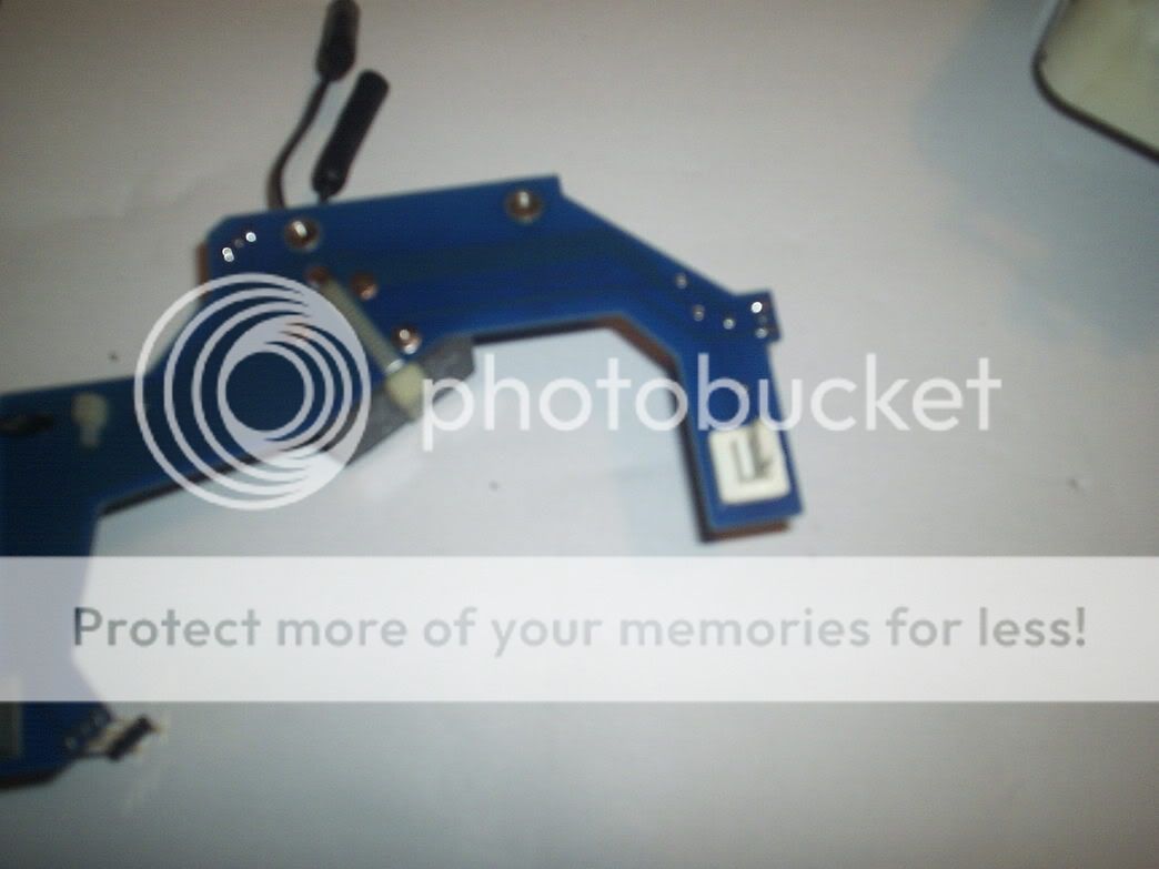
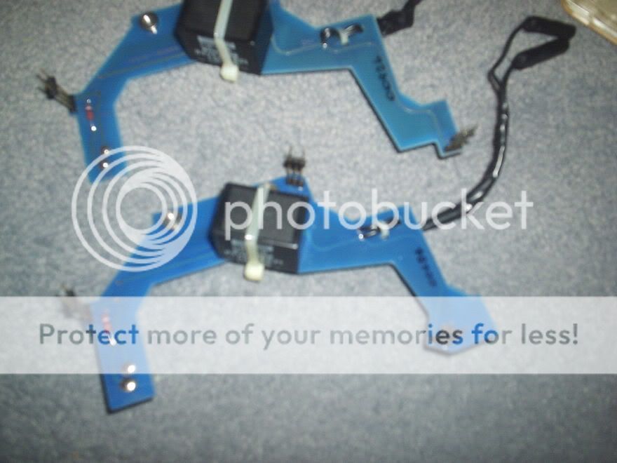
found this loose when i took my gauges off the (white plastic object) it should be soldered to the inverter board could this be why lights arent working would like to know what it is thanks. CN4 is written underneath
the plastic white bit
the plastic white bit

 19-12-2005, 04:51 PM
#4
PassionFord Post Whore!!

Join Date: May 2003
Location: SE
Posts: 9,226
Likes: 0
Received 0 Likes
on
0 Posts
IIRC thats where the power comes in from the car to the invertor, right?
If so try soldering it back in place seee what happens....
did you try to remove the bulb holder witht the big sticker round it saying "NON servicable do not remove"... as IIRC thats where it plugs into... Couldve been dodgy invertor unit and you have just damaged that bit removing it..
If so try soldering it back in place seee what happens....
did you try to remove the bulb holder witht the big sticker round it saying "NON servicable do not remove"... as IIRC thats where it plugs into... Couldve been dodgy invertor unit and you have just damaged that bit removing it..
19-12-2005, 04:54 PM
#6
PassionFord Post Whore!!
Join Date: May 2003
Location: SE
Posts: 9,226
Likes: 0
Received 0 Likes
on
0 Posts
the actual black box bit?? didnt get one seperate, bought the whoule lot from Ford, but I believe Dave Henshall has traced a possible replacement... there is a thread in here about it somewhere..
19-12-2005, 05:03 PM
#7
Regular Contributor
Thread Starter
Join Date: Jan 2005
Posts: 238
Likes: 0
Received 0 Likes
on
0 Posts
yep thats what i have done  bought a complete spare inverter including board ( cheers radman) so will put that on. do you think re soldering the old one will be ok. everything else came apart ok thats the first thing i took off
  That big sticker wasnt big enough
  thanks for getting back with the answer
That big sticker wasnt big enough Trending Topics
19-12-2005, 05:57 PM
#8
Regular Contributor
Thread Starter
Join Date: Jan 2005
Posts: 238
Likes: 0
Received 0 Likes
on
0 Posts
just looked at the pin layout on my board and the spare, they are slightly different, so pins which go to the fuel and temp gauges dont line up. i thought there was only one type of board but i guess not any idea's maybe small and big turbo are different ?
 19-12-2005, 06:18 PM
#11
PassionFord Post Whore!!
Join Date: Sep 2003
Location: Macclesfield - you'll never leave....!
Posts: 4,519
Likes: 0
Received 1 Like
on
1 Post
here is the RS data sheet...
http://documents.rs-components.com/r...OCBASE=techlib

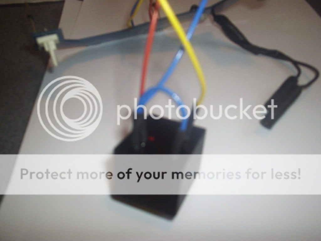
and here is the unit, u may have to mount it uside down and run wires to the original hole on the PCB as they robably wont line up ...
stock number: 267-8863 �25.48
see www.rswww.com
[/img]
http://documents.rs-components.com/r...OCBASE=techlib
and here is the unit, u may have to mount it uside down and run wires to the original hole on the PCB as they robably wont line up ...
stock number: 267-8863 �25.48
see www.rswww.com
[/img]
 19-12-2005, 10:52 PM
#16
PassionFord Post Whore!!

Join Date: Apr 2004
Location: Warsaw, Poland
Posts: 5,343
Likes: 0
Received 0 Likes
on
0 Posts
Originally Posted by Tandy
im not sure yet might try and get another second hand one and sell the one you sold me i dont think anyone knew there were different types, we live and learn 
One look into Microcat would tell you that mate
19-12-2005, 11:21 PM
#19
Regular Contributor
Thread Starter
Join Date: Jan 2005
Posts: 238
Likes: 0
Received 0 Likes
on
0 Posts
ok thanks, never thought there would be two types as in all previous posts about dash lights it has never been mentioned ( and there have been quite a few) never crossed my mind to look. Got to stage where im not far off sorting the little bits and pieces out just need to take my time. it will be worth it in the end
19-12-2005, 11:28 PM
#21
Regular Contributor
Thread Starter
Join Date: Jan 2005
Posts: 238
Likes: 0
Received 0 Likes
on
0 Posts
yep i think from now on i will do the same but at least i can sell the spare one if i choose, and go in search of the early one so not the end of the world. must get microcat up and running again
20-12-2005, 12:51 PM
#22
Part of the Furniture

Join Date: Aug 2005
Location: Luton - Vauxhall Country!!!
Posts: 183
Likes: 0
Received 0 Likes
on
0 Posts
Originally Posted by Dave Henshall
here is the RS data sheet...
http://documents.rs-components.com/r...OCBASE=techlib
and here is the unit, u may have to mount it uside down and run wires to the original hole on the PCB as they robably wont line up ...
stock number: 267-8863 �25.48
see www.rswww.com
[/img]
http://documents.rs-components.com/r...OCBASE=techlib
and here is the unit, u may have to mount it uside down and run wires to the original hole on the PCB as they robably wont line up ...
stock number: 267-8863 �25.48
see www.rswww.com
[/img]
Paul
22-12-2005, 03:13 PM
#23
Regular Contributor
Thread Starter
Join Date: Jan 2005
Posts: 238
Likes: 0
Received 0 Likes
on
0 Posts
ordered new inverter from Rs and re soldered the white connector i broke off managed to fit a couple of new pins on the connector by drilling two very small holes next to the original pins. inserted two ne pins in the holes so they were touching the original ones and soldered to the board. tested with meter all ok. Have also removed old inverter will fit new inverter when it turns up and see how it goes 

 09-01-2006, 08:54 PM
#26
PassionFord Post Whore!!
iTrader: (1)

Join Date: Aug 2003
Location: Hampshire
Posts: 3,834
Likes: 0
Received 0 Likes
on
0 Posts
Originally Posted by Paul_Painter
Originally Posted by Dave Henshall
here is the RS data sheet...
http://documents.rs-components.com/r...OCBASE=techlib
and here is the unit, u may have to mount it uside down and run wires to the original hole on the PCB as they robably wont line up ...
stock number: 267-8863 �25.48
see www.rswww.com
[/img]
http://documents.rs-components.com/r...OCBASE=techlib
and here is the unit, u may have to mount it uside down and run wires to the original hole on the PCB as they robably wont line up ...
stock number: 267-8863 �25.48
see www.rswww.com
[/img]
Paul
Paul, have you done this yet?????
10-01-2006, 02:27 AM
#27
Regular Contributor
Thread Starter
Join Date: Jan 2005
Posts: 238
Likes: 0
Received 0 Likes
on
0 Posts
i have just wired in the new inverter and put gauges back together ( yesterday ) when i get a chance will try in car i have got some pic's and will upload if all goes well
20-01-2006, 08:07 AM
#31
Regular Contributor
Thread Starter
Join Date: Jan 2005
Posts: 238
Likes: 0
Received 0 Likes
on
0 Posts
the new inverter works and all my gauges now light up i will up load some pic's when i get a chance hopefully the pic's will be clear enough for people to see what ive done
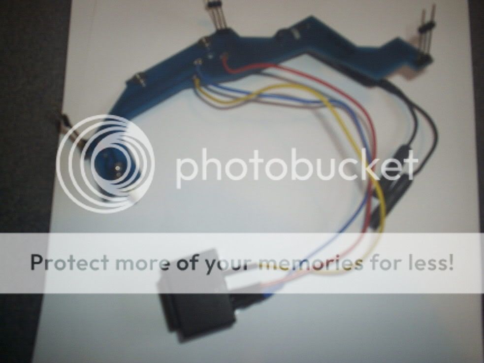
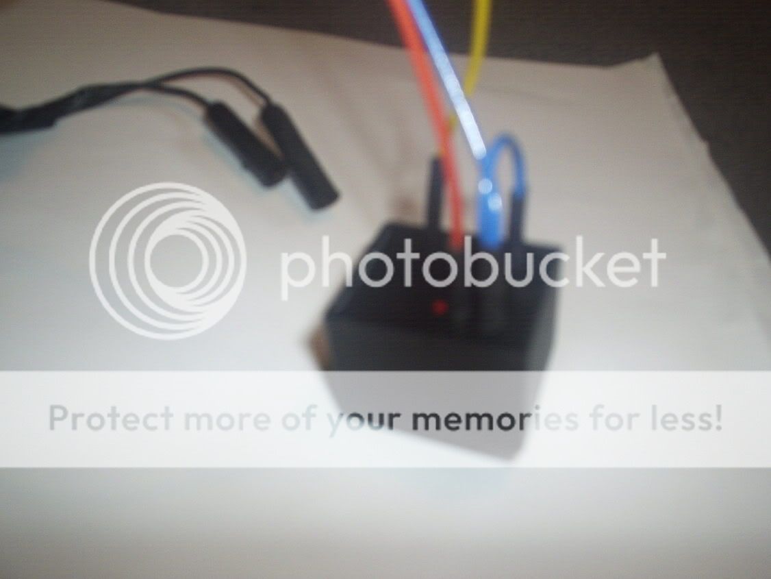
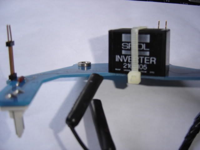
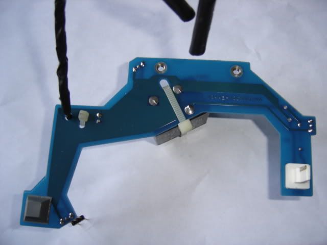
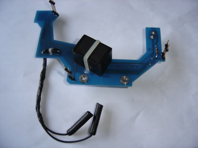
the pic's arent the best but anyone fitting this inverter should be able to see what i have done. The new inverter comes with 4 pins as opposed to 3 so thats why there is a loop (extra blue wire) going from one pin to another. as i said all gauges work big thanks to all who helped
the pic's arent the best but anyone fitting this inverter should be able to see what i have done. The new inverter comes with 4 pins as opposed to 3 so thats why there is a loop (extra blue wire) going from one pin to another. as i said all gauges work
 22-01-2006, 02:24 PM
#35
Regular Contributor
Thread Starter
Join Date: Jan 2005
Posts: 238
Likes: 0
Received 0 Likes
on
0 Posts
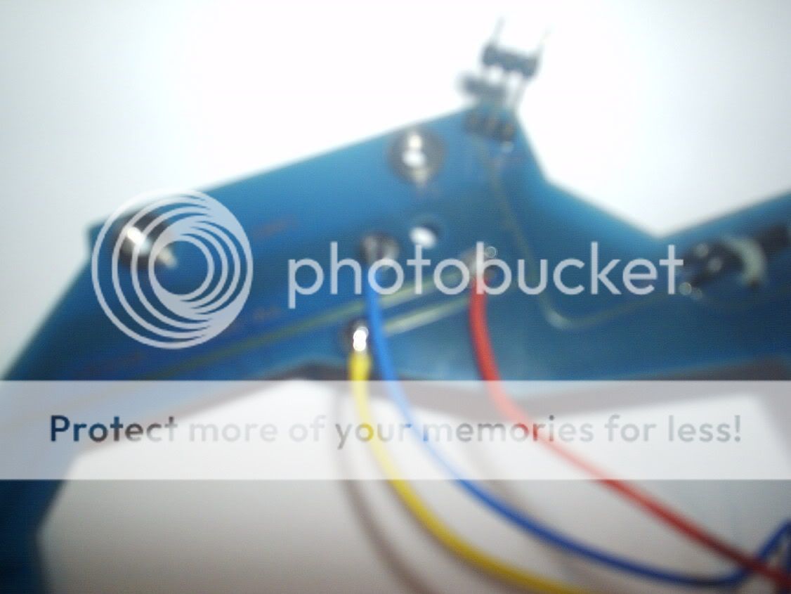
When you de solder your original inverter you should see everything alot clearer. On the new inverter The pins are offset the pins on the left side are closer together so as you look at the picture :
The bottom left pin BLUE WIRE
The bottom left and right pin joined by BLUE WIRE (loop)
Top left RED WIRE
Top right YELLOW WIRE
did you get the pm i sent you ?
also when soldering the yellow wire to the board angle it up slightly not down like i have done just gets in the way cheers
The bottom left pin BLUE WIRE
The bottom left and right pin joined by BLUE WIRE (loop)
Top left RED WIRE
Top right YELLOW WIRE
did you get the pm i sent you ?
also when soldering the yellow wire to the board angle it up slightly not down like i have done just gets in the way cheers
28-09-2006, 11:59 AM
#39
15000
Join Date: Nov 2005
Posts: 46
Likes: 0
Received 0 Likes
on
0 Posts
Hi, yesterday arrived the inverter that Tandy has used and today I try to put it on. But from the schema I see that there is a sort of short-circuit between point A and 1 that are +12vcc and one of the two phases of 110vac. Has this a sense? Someone could confirm this? Any help would be very appreciate.
Ciao
Ciao
02-10-2006, 09:19 AM
#40
15000
Join Date: Nov 2005
Posts: 46
Likes: 0
Received 0 Likes
on
0 Posts
Originally Posted by Duca
Hi, yesterday arrived the inverter that Tandy has used and today I try to put it on. But from the schema I see that there is a sort of short-circuit between point A and 1 that are +12vcc and one of the two phases of 110vac. Has this a sense? Someone could confirm this? Any help would be very appreciate.
Ciao
Ciao
I had put the whole thing on and.... voil�!! It goes
Even better than the real thing!! Probably the old illumination were affected by the bad status of the old inverter but now the illumination is more clear. Thx to all