Composite chassis/monococque construction.
 09-05-2013, 02:57 PM
#1
Anyone got any experience in this??
Especially when it comes to carbon composites and honeycomb carbon tubs, Not much information publicised due to confidentiality agreements etc and there appears to be little technical reference books on the matter either.
Only seems to be a few kit cars or low volume bodyshells out there in GRP where the details of thier make up are widely known.
Nothing in the hypercar or race world is easily available.
NOw obviously i can just in essence copy a proven design, rejig it for my chosen platform then re-run Finite element analysis and CAD testing on it, but thats not really the best approach as it rather design it from scratch using "industry common" approaches matched for my objectives rather than bodge someones design.
Also does anyone know of any specific legal implications for IVA kit car registration?? the manual is deliberately vague and the only formal inspection of a chassis design is to check it appears substantial enough for the job in hand. And thats by a IVA inspector with no specific chassis construction knowledge. Are there any unwritten rules or guides that need to be kept to in terms of getting it registered??
I know GTM and murtaya have done several composite monococques with no problems but it wouldnt surprise me if an IVA man suddenly became cagey if i said "i designed and made it"
Also anyone know if there are any specific MSA or FIA rulings for reinforment plates for harnesses and bolt in Rollcage mountings on composite chassis? Want to design in the appropriate inserts from the start so it can be CAD modelled accurately.
 09-05-2013, 08:34 PM
#3

If your just looking for info on methods of construsction using honeycomb/reinforced plastics ect it maybe worth checking out some avation stuff as its quite common, as far as building a chassis your self and putting it on the road i have no idea but it sounds fun 
09-05-2013, 09:05 PM
#4
Advanced PassionFord User

I've no direct experience of designing or building them, but I've also looked into doing it a bit.
The IVA is a bit of a joke, it goes into corner radii for switchgear, but the chassis (for steel) is a cursory inspection of the finished and painted chassis for any obviously crap welding etc. I'd warrant your FE calcs would be enough to satisfy that.
Coming on to the FE itself (which I do know a little about) while it is easy enough to model most things, the issue is always boundary constraints. You'd want to test chassis stiffness but just what forces do you want to test it against in terms of bump etc? Would you want to model impacts? How do you deal with local stiffness? (think wings which bend when you press on them etc)
On top of that, when building the actual model, how would you model the connections between one material and the other? You'd need to look into how that's done in the aero and marine industries to determine the appropriate modelling methods.
It may be worth getting hold of the Australian IVA equivalent, they demand allsorts of proof the chassis if of acceptable design and construction even if steel and may offer some guidance on composite construction.
I've just had a look in the blue book (2011) and it assumed a steel construction, referring only to reinforcement plates welded in place. I guess again you'd want to consider an impact situation in your FE calcs and ensure that the roll cage deforms and intrudes dangerously on the passenger space before the feet punch through the floor (use iterative increased in loading to determine the appropriate area for the reinforcement plates.)
Finally I guess it's obvious to say, but as you're registering it for road use, I doubt it's a flyweight hillclimber, so build in generous safety factors!
09-05-2013, 10:12 PM
#5
Ive plenty of the raw material data, bonding adhesive and relative joint data for joining panels etc as well as chassis inserts.
In terms of the FE i was going to us the parameters used on a couple of chassis design reports a uni did on relative stiffness and relative performance of OEM chassis versus a student designs. They used a set of parameters used by MIRA and others to model OEM designs, so that should do the basic performance. Its some ISO test standard from what i was reading...
Crash performance I need to find some test data on road use. At the moment i only have the minimum criteria for various motorsport and formula requirements for crash structure performance.
Over engineering it is the biggest danger considering the chassis designs ive seen and my initial design thoughts.
09-05-2013, 10:21 PM
#6
PassionFord Regular

Right warren. I think you are touching on new ground here. Basically iva inspectors are glorified moters and dont have the first idea about this stuff.
Basically and i know its a shitter but have a word with tue dvla. I guess you are wanting roadworthyness thrown in.
I think as you are going alone and i have never read about anyone going as far as you with regards to safety and even seat mounting, you are in un charted terroitry.
And then cad designing on top. I think pf may be outta the reach of what you want and speaking on aviation forums better.
But good luck. Whatever it is sounfs awesome
09-05-2013, 10:24 PM
#7
PassionFord Regular
And could you not jist build the chassis and have them check it over. Yes cost to possible fail is high but im not sure they actually have anything in writing for this stuff
Trending Topics
10-05-2013, 09:26 AM
#8
Yeah i do get the impression that IVA testers are just glorified MoT testers, however you would like to think the people who wrote the manual would have the requisite engineering background............. one would hope....
There are GRP monococques out there, eg the Murtaya kit car and the GTM libra both of which use a basic (aka shit) chopped stranf mat based GRP chassis - aka decades old boat building technology
The impression i get with a lot of the bureacracy today is that because in "amatuer build" terms a carbon chassis is unheard of, i may come across problems because in essence people are scared of the unknown. And no one wants to be the person who signs off on something that could potentially crash and kill people later on - i imagine thats how it will be viewed.
Despite the fact that as a performance material (even in crashes) it out performs GRP in every way. Not to forget i will be adding in deliberate "crash structures" to the sills and front and rear using the motorsport industry standard of aluminium honeycomb based crash boxes.
Ironically a lot of the bonding data I can rob from lotus as they did extensive testing of structural adhesives when they designed the elise to the extent that the elise's alloy box section chassis is mostly bonded together rather than welding as they found the bonding was stronger, needing only the odd rivet here and there to prevent "peeling" of the bonded joint in heavy crashes.
Thing is I KNOW there is a lot of info out there in the top end motorsport scene on such construction but its very much a closed arena unless you have the right contacts. In fact information sharing in the advanced composites industry is fairly absent!! The company i work for has in some cases lost trade because we have an open policy of information sharing. Not saying we share information gained in confidence in contracts etc but theres a lot of knowledge on how to do x, y and z that people wont tell you, but they will happily charge you lots of money to make it for you - yet the same people get upset that we will tell customers how to do it themselves.
07-10-2013, 09:31 PM
#9
bit of an update.
Been slowly learning CAD to get my design shape down roughly.
So its time to test some materials! I'm looking at either using a 20mm or 10mm foam or alloy honeycomb core material with carbon either side.
So this was a practical but not extremely scientific test of a sample panel i have made. This panel was made of 2mm carbon fibre, 20mm aluminium honeycomb and another 2mm of carbon.
I expected it to be a massive overkill from other carbon tubs ive seen, but Ive done it for a bench mark.
First of all put it between bricks and got me and my mate to jump on it - no visible damage and no visible deflection while loaded
so i thought "fuck it" and decided to run it over with my 4x4 bear in mind the weight distribution is such that the front wheel i used was loaded to about 500kg spread over the tyre contact patch.
The test piece is 50cm by 30cm.
Test one - simple drive on it:
no measurable deflection and no visible damage afterwards.
Time to up the anti.....
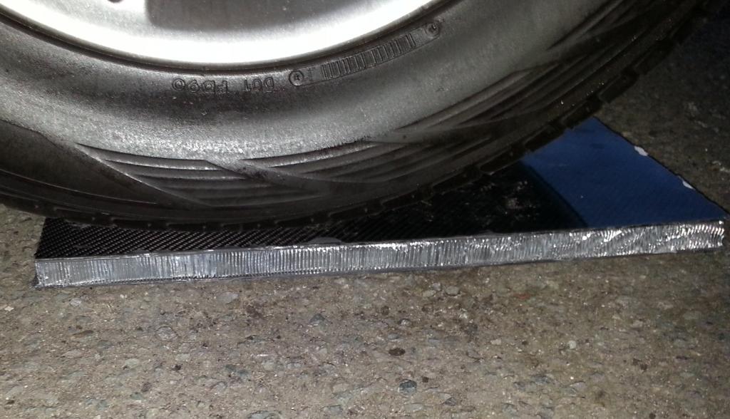
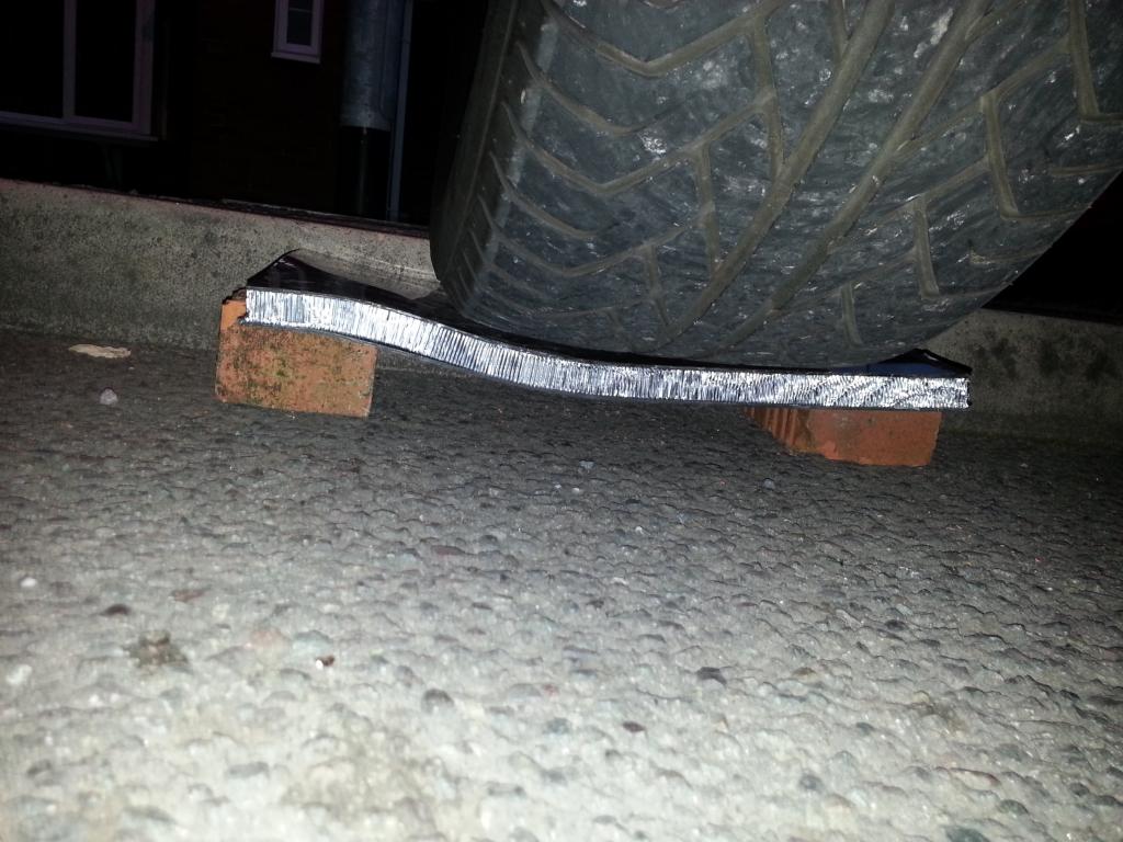
Prop it on a brick against the kerb, and drive onto it like a ramp:
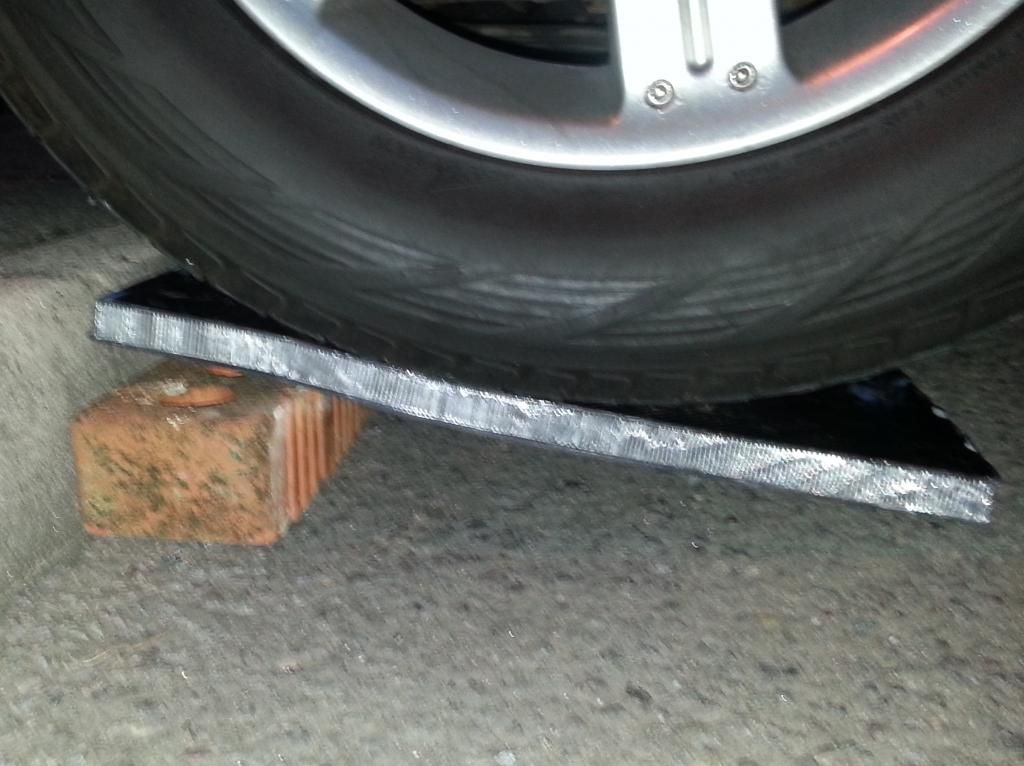
about 3-5mm measurable elastic deflection. No structural damages except minor gouges on surface of carbon where it rested on the brick and ground.
So up anti again and just rest on the kerb:
Almost identical results to above.
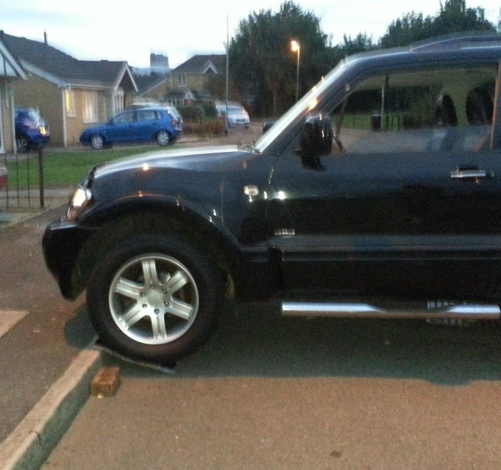
Proof it is a heavy 4x4 and not a mini:
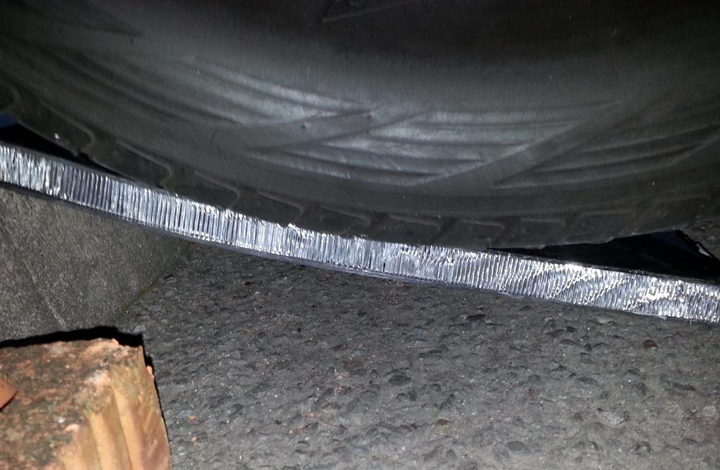
The final test, put it between 2 bricks and drop off the kerb heavily. See how it does with a bit pf shock loading!!
The defelection was permenant this time with the shock loading! No obvious cracking in the carbon but the honeycomb does appear crushed in places.
Although not massively scientific, has confirmed that a 20mm core is overkill for the main parts of the chassis and 10mm is likely to be plenty. 20mm will be reserved for the high loading members.
Been slowly learning CAD to get my design shape down roughly.
So its time to test some materials! I'm looking at either using a 20mm or 10mm foam or alloy honeycomb core material with carbon either side.
So this was a practical but not extremely scientific test of a sample panel i have made. This panel was made of 2mm carbon fibre, 20mm aluminium honeycomb and another 2mm of carbon.
I expected it to be a massive overkill from other carbon tubs ive seen, but Ive done it for a bench mark.
First of all put it between bricks and got me and my mate to jump on it - no visible damage and no visible deflection while loaded
so i thought "fuck it" and decided to run it over with my 4x4
bear in mind the weight distribution is such that the front wheel i used was loaded to about 500kg spread over the tyre contact patch.The test piece is 50cm by 30cm.
Test one - simple drive on it:
no measurable deflection and no visible damage afterwards.
Time to up the anti.....
Prop it on a brick against the kerb, and drive onto it like a ramp:
about 3-5mm measurable elastic deflection. No structural damages except minor gouges on surface of carbon where it rested on the brick and ground.
So up anti again and just rest on the kerb:
Almost identical results to above.
Proof it is a heavy 4x4 and not a mini:
The final test, put it between 2 bricks and drop off the kerb heavily. See how it does with a bit pf shock loading!!
The defelection was permenant this time with the shock loading! No obvious cracking in the carbon but the honeycomb does appear crushed in places.
Although not massively scientific, has confirmed that a 20mm core is overkill for the main parts of the chassis and 10mm is likely to be plenty. 20mm will be reserved for the high loading members.
Last edited by Psycho Warren; 07-10-2013 at 09:34 PM.
08-10-2013, 09:16 AM
#10
The next stage now is to make 10mm cored panels in foam and honeycomb and do some more accurate static loading tests.
The 24mm thick panel above comes in at 10kg per square meter which is too heavy for what i want. Its not heavy when you consider that nothing that weight per sqm will match it performance wise unless i buy expensive nomex honeycombs from aerospace!
The 24mm thick panel above comes in at 10kg per square meter which is too heavy for what i want. Its not heavy when you consider that nothing that weight per sqm will match it performance wise unless i buy expensive nomex honeycombs from aerospace!
08-10-2013, 09:51 AM
#11
Regular Contributor

Join Date: Aug 2012
Location: North end of things
Posts: 249
Likes: 0
Received 0 Likes
on
0 Posts
Nice bit of testing - good to see actual results.
My cousin would be all over this. He's a design engineer for Bentley but he's been building his own car mostly from composites in his spare time (although he's made a tubular frame for his chassis)
Think its about ready for making the bodymoulds now.
Anyway - looking forward to more updates!
Jordan
My cousin would be all over this. He's a design engineer for Bentley but he's been building his own car mostly from composites in his spare time (although he's made a tubular frame for his chassis)
Think its about ready for making the bodymoulds now.
Anyway - looking forward to more updates!
Jordan
08-10-2013, 10:58 AM
#12
I'm going for the full composite chassis.
Having had a look over a Murtaya which is mostly chopped strand mat, its not that difficult to make it stiff enough. The murtaya is fairly basic. Things like the moulded strut towers are only like 3 or 4 mm thick fibreglass and the same for the subframe mounts. Hardly massive technology in thier design either.
Mine should be a nice strong box section construction with triangulation to stiffen it up.
10mm panels is minimum IMO. Plus things like strut towers will have metal plate inserts within the carbon to strengthen it even more.
08-10-2013, 03:26 PM
#13
10K+ Poster!!

This is going to be one hell of a thread! What are you going to do, turn the puma into a composite chassis or design a totally new car?
09-10-2013, 02:19 PM
#19
10K+ Poster!!

 10-10-2013, 09:23 AM
#22
Well im not going for mega power. Im keeping the current engine for the time being which is only 380bhp.
But im hoping to get the weight well under a ton. 800kg would be nice but may be a struggle with the heavy 4wd running gear.
The car is currently 1250kg with a full interior and overly heavy GRP arches etc etc Just stripping the interior on a puma can save 100Kg easily so i think well under a ton is realistic.
With my current engine its good enough to put on a new turbo and bits and bobs to take it comfortably to 450bhp so in a car weighing say 900kg would be 500bhp per ton which would be fast.
29-10-2013, 12:38 AM
#23
test panel No 2.
This one is a 10mm foam core with 1mm carbon skins. So less than half as thick as the previous test panel.
Used my mates lighter car for this test working out about 300kg for one front wheel.
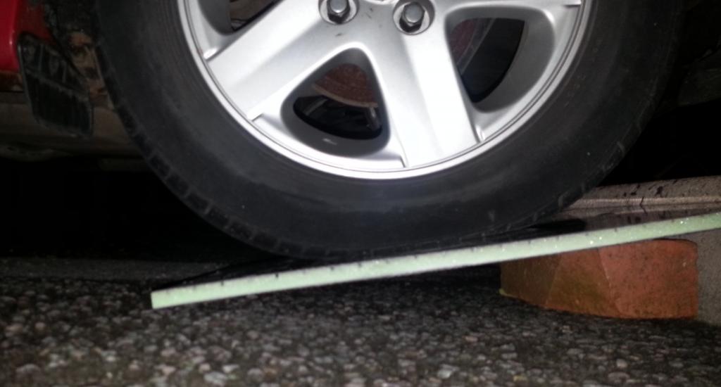
On a brick same as before.
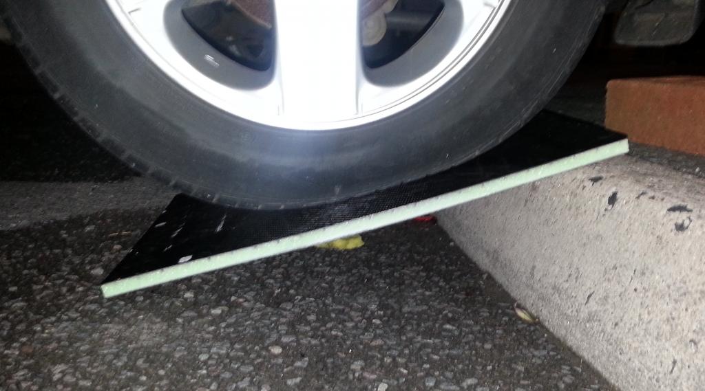
Directly on the kerb.
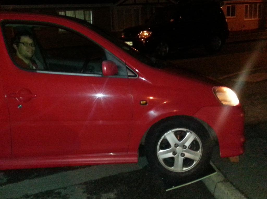
Proof its a car not just a wheel balanced on the board!!
Virtually no deflection whatsoever and certainly no permenant damage apart from scratches from edge of the brick.
I will run it over with the 4x4 at the end of the week. Although i expect it will get crushed
This one is a 10mm foam core with 1mm carbon skins. So less than half as thick as the previous test panel.
Used my mates lighter car for this test working out about 300kg for one front wheel.
On a brick same as before.
Directly on the kerb.
Proof its a car not just a wheel balanced on the board!!
Virtually no deflection whatsoever and certainly no permenant damage apart from scratches from edge of the brick.
I will run it over with the 4x4 at the end of the week. Although i expect it will get crushed
Last edited by Psycho Warren; 29-10-2013 at 12:44 AM.
29-10-2013, 10:50 AM
#24
Not Crazy, just Unwell
I reckon it stands a very good chance against the 4x4. What tests could you apply on say an impact where forces are multiplied over a larger area? At a guess from the pictures, an impact would fair pretty well tbh. What other cores have you got in mind?
29-10-2013, 11:31 AM
#25
Yes impact would fair pretty well. however, i am engineering crush/crash structures into the design. Eg alloy honeycomb is commonly used as impact attenuators in composite cars as well as most of the crash test "impact blocks" are honeycomb to simulate impacting with a car that deforms (rather than an immobile concrete block). So plenty of data available to determine a good crash box design. The sills, pillars, rear panel and front chassis legs will all be crash structures. They are also bonded on seperatly to the main chassis structure thus replaceable in light impacts. Dont want to get punted in the rear by some cunt at the lights and it be written off for a minor bump
29-10-2013, 01:21 PM
#26
Not Crazy, just Unwell
Excellent thinking! So how does the bonding work? How strong would it be say in a small bump to a rear quarter? I'm assuming the chemical structure of the bonding agents have a decent breakdown time of 100+ years?
29-10-2013, 03:05 PM
#27
Yes the glues are long term stable as are the resins.
How strong is a piece of string lol. But the impact attenuator panels all have set ratings for how much force they can take before deforming and how much they deform. I could in theory use thier data to make a rear impact panel that can take say for example a 10mph impact from a 1 ton car with x mm of deflection.
That is ignoring the strength of any laminates over the top of the panel ie they will need to smash through the rear bumper and rear panel before they touch the impact panel.
In reality I have no intention of spending yonks designing an impact panel to take x, y and z force. It will be overengineered based on a minimum standard i am happy with. Im not aiming to pass NCAP just make sure its stiff enough to not be a death trap!
29-10-2013, 03:28 PM
#29
Most of it will be foam cored carbon fibre/carbon twaron panels. (twaron is a different brand of aramid fibre to kevlar but basically the same) Will be some panels of honeycomb higher up to save weight as well as aluminium inserts and load spreading panels throughout where things need to be bolted into the carbon. eg FIA seat belt anchors through a load spreading plate to stop rip through. All suspension mountings will have large metal load spreading plates to bolt through etc.
08-11-2013, 08:54 AM
#31
Well ive decided its going to be 25mm core floor pans and 10mm core for most of the rest with a few areas of honeycomb (on top of crumple zones).
Awaiting to rent a unit so i can strip the interior of the puma properly to get the measurements i need for the CAD work to begin. Then its design it in CAD.
After that its build a jig table to put the car on to fix the suspension points in space relative to the car, then i can take the bodyshell off and with the suspension points all fixed in space, ive got a practical reference point to work around as i part assemble bits of the chassis in foam ready for moulding.
Its one of those projects that will have long periods of little visible progress then spurts where things come together real quickly.
08-11-2013, 08:55 AM
#32
Too many posts.. I need a life!!

Hi Warren, have you had any subjects on composites?
The bending stiffness, as you have shown, will increase dramatically with the use of a core material (honeycomb).
A friend of mine at uni did extensive research on methodology and layup-design for formula student this year. This year (3rd year of competing) they do a complete monocoque design.
I could send you his thesis if you are interested. Also, I have a introduction compendium to composite design I could send you. Its made by a really skilled professor of mine, and covers the basics. In combination with the thesis I would imagine you would be busy for a while.
I�m actually specializing in composite materials; and the main problem of using it is the inaccuracies while producing parts. There are several failure criteria (safety factors) you can employ during FEA, however it demands highly skilled production.
What software are you using for FEA? I recommend importing a shell model in to abaqus, and design it from there, though this will require an insane amount of work!
Are you a mechanical engineer?
Last edited by nixon_2wd; 08-11-2013 at 09:04 AM.
08-11-2013, 09:03 AM
#33
Hi Nixon, I studied some composites during my early days studying aeronautics while covering materials and material failure so ive some knowledge of the subject, plus i work for a carbon composites company now so its daily bread and butter with the basic stuff.
I'd be very interested in reading the thesis!
We supply a lot of uni's doing Formula Student over here in the UK, although most are still using the stock Formula steel chassis with only the higher end and better teams moving over to composite monococques.
The hard part for a lot of the poorer funded teams is to prove structural equivilency which is required for the competition both in mathematical calculations and FEA as well as often a practical test.
I will be doing most my CAD through solidworks as i have access to the package through work.
In dimensional terms for CAD, its the suspension pick up points and dimensonal extremities of the monococque that are important to me. I have no intention of 3d modelling the entire body panels of the car!!
08-11-2013, 09:10 AM
#34
Too many posts.. I need a life!!
Hi Nixon, I studied some composites during my early days studying aeronautics while covering materials and material failure so ive some knowledge of the subject, plus i work for a carbon composites company now so its daily bread and butter with the basic stuff.
I'd be very interested in reading the thesis!
We supply a lot of uni's doing Formula Student over here in the UK, although most are still using the stock Formula steel chassis with only the higher end and better teams moving over to composite monococques.
The hard part for a lot of the poorer funded teams is to prove structural equivilency which is required for the competition both in mathematical calculations and FEA as well as often a practical test.
I will be doing most my CAD through solidworks as i have access to the package through work.
In dimensional terms for CAD, its the suspension pick up points and dimensonal extremities of the monococque that are important to me. I have no intention of 3d modelling the entire body panels of the car!!
I'd be very interested in reading the thesis!
We supply a lot of uni's doing Formula Student over here in the UK, although most are still using the stock Formula steel chassis with only the higher end and better teams moving over to composite monococques.
The hard part for a lot of the poorer funded teams is to prove structural equivilency which is required for the competition both in mathematical calculations and FEA as well as often a practical test.
I will be doing most my CAD through solidworks as i have access to the package through work.
In dimensional terms for CAD, its the suspension pick up points and dimensonal extremities of the monococque that are important to me. I have no intention of 3d modelling the entire body panels of the car!!
I will be getting the thesis for you right away.
Our FS team is spoiled...
I have also heard that its the suspension pick ups is the hardest part.
What company do you work for? I would be interested in following this project so please make a thread when you start
08-11-2013, 11:30 AM
#35
Some of the FS teams really are on a pikey low budget and it shows on thier cars even worse is when you give hours of advice to the students on how to laminate and make a part such as a nose cone, they then ignore EVERYTHING you said, do it thier way that youd already told them was wrong, and surprise surprise it all fucks up - like I predicted. They then ring up asking how to fix it Well if youd listened to my advise in the first place..........
Suspension pick up points need to be accurate hence the jig. The parts needing suspension point inserts in metal will be moulded ON the jig in place so no matter how wonky it comes out, the suspension pick up points will still be straight.
even worse is when you give hours of advice to the students on how to laminate and make a part such as a nose cone, they then ignore EVERYTHING you said, do it thier way that youd already told them was wrong, and surprise surprise it all fucks up - like I predicted. They then ring up asking how to fix it Well if youd listened to my advise in the first place..........Suspension pick up points need to be accurate hence the jig. The parts needing suspension point inserts in metal will be moulded ON the jig in place so no matter how wonky it comes out, the suspension pick up points will still be straight.
09-11-2013, 10:47 AM
#37
You should post pictures of how you lay the panels up too unless you don't wan tto give that away. Its always interesting seeing how someone does it at home as such.
I only ever see how the large aerospace OEMs make carbon fibre parts with millions spend on automated fibre placement machines etc.
It was yourself made the carbon bonnet at home wasn't it?
We are currently "storing" a serious amount of aerospace carbon fibre cloth at present which is passed it date to be used in commercial flying planes but obv as its dry its perfect for making car parts etc. Its around �10,000 a roll and we have around 60 rolls of it which we are allowed to use around 6 rolls of it for ourselves. They are around 1.5 foot diameter and 2.5 meters long
Work has toyed with the idea of buying a resin injection machine, we also have facility to machine up to 4m by 2 meter mould tools made from tooling board so could make some nice interesting parts. Tho obv the first layer would need to be a nice weave as the aircraft cloth we have looks shite tbh.
Last edited by daviddunlop83; 09-11-2013 at 10:48 AM.
09-11-2013, 11:10 AM
#38
Not Crazy, just Unwell
Would it not be easy to cosmetically make it look decent after it's been produced? Like laying a thin layer over the top? Or would it be easier to coat with paints?
09-11-2013, 11:19 AM
#39
PassionFord Post Troll
Interesting thread, id love to watch you build a full shell out off this stuff, how much do you think it would cost?
Not sure what car id build, possibly a E-Type, or a 911
Not sure what car id build, possibly a E-Type, or a 911