1985 Reliant SS1 rebuild/upgrade
 11-04-2010, 12:06 PM
#1
15000
Thread Starter

Join Date: Apr 2010
Location: Leeds
Posts: 23
Likes: 0
Received 0 Likes
on
0 Posts
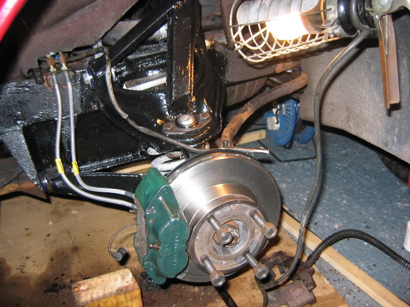
Hello everyone - I hope it's ok for me to tell you about my project as it's not a Ford. It does however have a Ford engine (was 1600cvh, now it's a 2 litre Zetec), gearbox (type 9) & Sierra diff/driveshafts. The suspension is based on Chevette wishbones at the front with Reliant designed trailing arms at the rear. Front brakes would have been a pair of solid discs (not sure what off) with 4 pot calipers from a Metro I've uprated these to a pair of vented discs from a Scimitar specialist along with a pair of 4 pot calipers from a Metro Turbo. The rear brakes are Sierra drums I think.
I've had the car for just under 2 years & in that time I've ony driven it about 250 miles - mainly to work a couple of summers ago. It was fun to drive & handled well (rear wheel drive) but not that fast (ina straight line at least)! As for the looks well you either like it or hate it (a real marmite car) - I happen to like it but have to admit that it's not the prettiest car ever made! I had money burning a hole in my pocket & bought it with my heart rather than my head. I paid far too much for it but it does have the desirable hard top which just about makes it bearable for winter use - the heater doesn't work very well though so while you'll stay dry (mostly) you'll also freeze! The headlights work, which is important as the mechanisms are s0ds to strip down & put back together apparently. Having got the thing home & having driven it a few times I read somewhere on the web that the Zetec 2 litre engine would bolt directly to the gearbox (using a different flywheel/clutch plate). My friends' cousin just happened to have a 2 litre Mondeo sitting on his mums drive & so the seed was sown. Three weekends later the Zetec engine was sitting in my garage & I made the decision to take the Reliant off the road & have done any work that needed doing to it. The SS1 came in a variety of flavours, the most desirable being the ones with a galvanised chassis & Nissan 1800 turbo power ..... unfortunately my car has neither of these. The lack of galvanising meant that the sills were shot (even though it had 12 months MOT when I bought it) as were the lower parts of the A & B posts. The rest of the chassis, from what I could see of it, appeared sound. I bought a couple of sills (available from Scimitar specialists) & arranged for a couple of chaps, who'd previously made a very good job of restoring a Datsun 120Y coupe & an MGB GT for a couple of workmates, to fit them for me & also to repair as required the A & B posts. They wouldn't be able to take the car for some months due to other commitments so I started stripping the front suspension & brakes down in order to fit uprated polyurethane bushes & to fit bigger vented disc brakes with calipers t hat I mentioned earlier. I did all the suspension/brake work over the Winter of 2008/2009 (& yes it was freezing in the garage & yes every last nut/bolt was seized solid). I had the chassis repairs done in 2009 & had it MOT'd just after all the work had been done. Unfortunately it failed on various things - most of which are electrical in nature. On a glassfibre/plastic bodied car electrical problems are often a result of having a poor earth but these problems seem to have stemmed from a combination of ancient wierd wiring (courtesy of Reliant) & seriously corroded bulb holders/lamps.It's all sorted now & I've beefed up the earth points too just in case
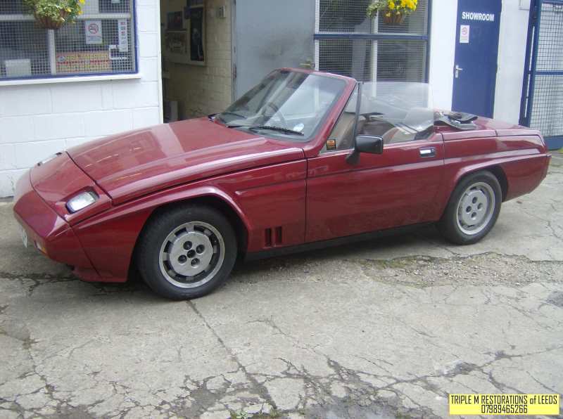
The car as bought:

The front suspension (drivers side) after being stripped & rebuilt - the shocks are inboard on these cars so not visible in this photo.
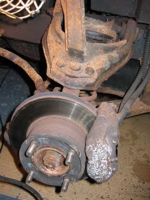
Passengers side front suspension before I started stripping it - lots of surface rust but no serious corrosion. Corrosion can affect these cars badly - anywhere can rust & there are well documented cases of wishbones cracking around the balljoint mounting with, obviously, disastrous consequences.
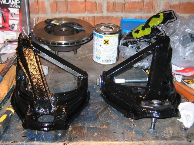
Strengthened wishbones - the diagonal bits on each wishbone are new.
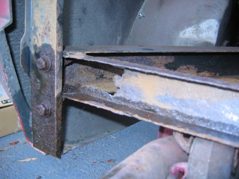
A small amount of corrosion at the rear of the chassis - this was sorted when the new sills were fitted & it's all nice & solid again now.
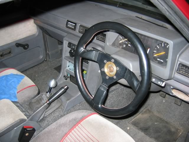
The interior - quite a comfortable place to be if you can live the cacophony of rattles, creaks & squeaks!
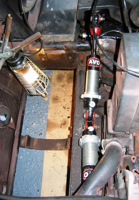
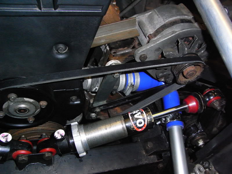
New shocks fitted - we're looking down on the engine bay in this shot (engine to the right, radiator to the left, spare wheel (not there) goes in between), the shocks came off an SS1 racer/hillclimber are adjustable & will accept coilover springs if/when I get round to fitting some.
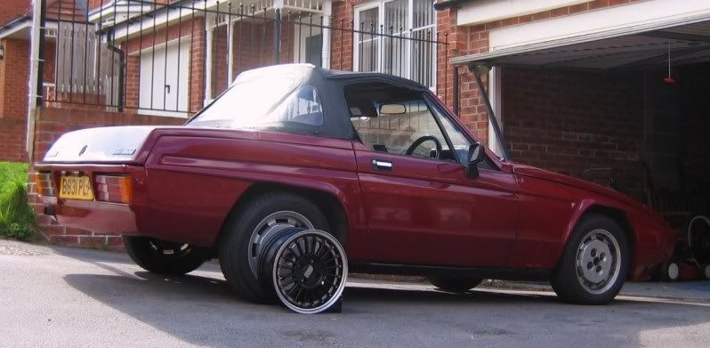
This is how I hope it'll end up looking one day - one of the alloys I got for Chrimbo last year is offered up for effect. The pcd is correct but the offset is all wrong & they foul the brake calipers on the front so I'll need some meaty spacers. They're not exactly high on the list of priorities & will have to wait until I can afford to buy some tyres for them.
I dropped the car off at the welders so that they could replace both sills & do any other repairs to the chassis as necessary.
Here�s the car pre-stripdown � doesn�t look too bad does it?
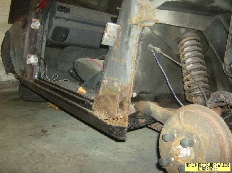
Here�s a shot of the passengers side sill after the door & both wings have been removed � doesn�t look too good does it?
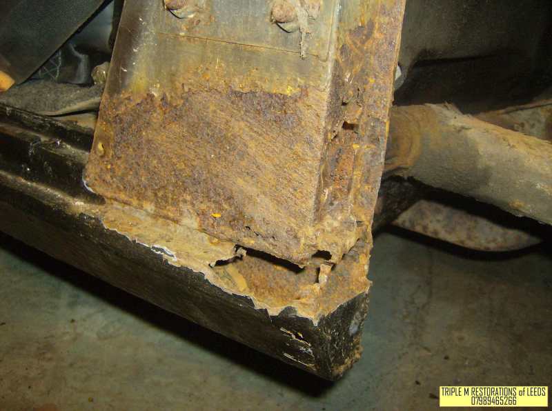
Oh dear oh dear! Close up of the rear of the sill - showing rust in the sill section & also part way up the B post.
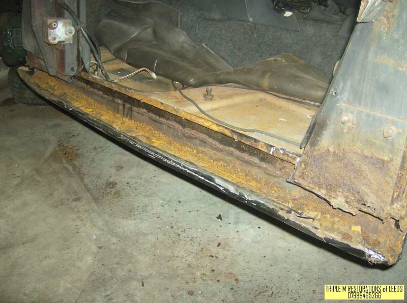
Sill partially stripped off the car � rusty along its entire length L
Shows the rust in the B post more clearly - reel for the seat belt mounts to this!!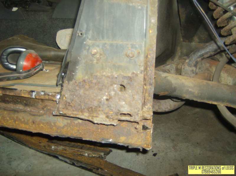
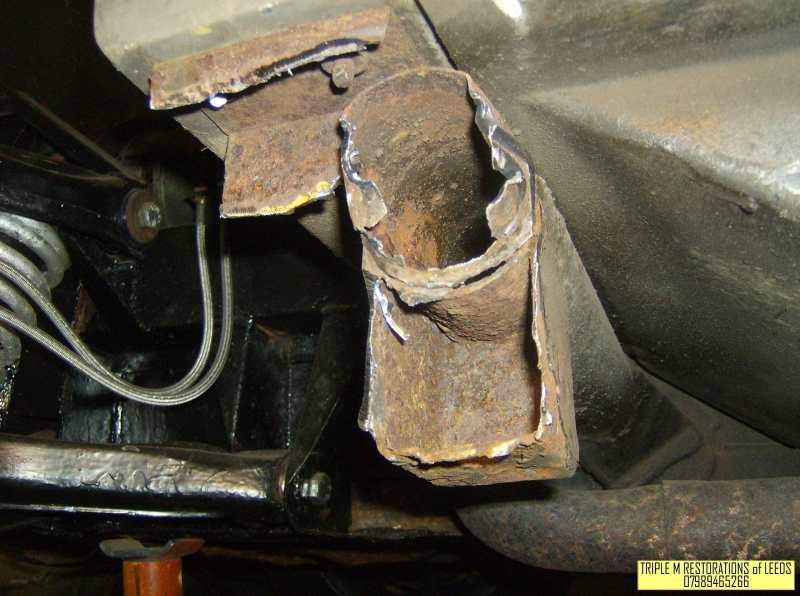
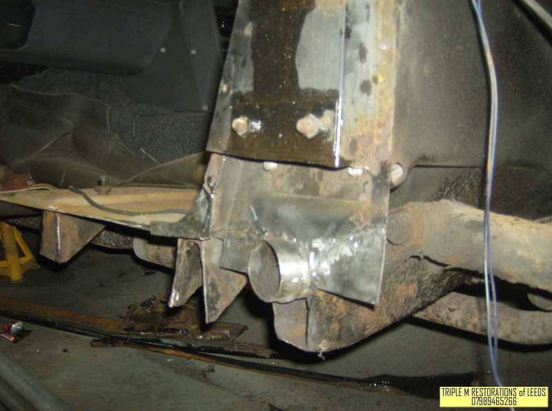
Shot showing the front outrigger & jacking point on the passenger�s side - they've started cutting the rot out in this pic. The two bolts at the top of the pic mount the body tub to the chassis.
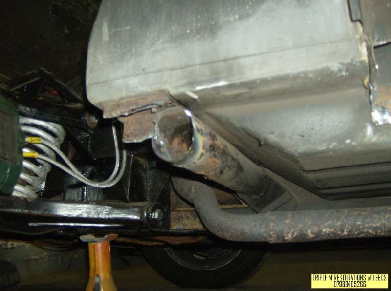
The front outrigger again but this time with new metal welded in & the old jacking point removed.
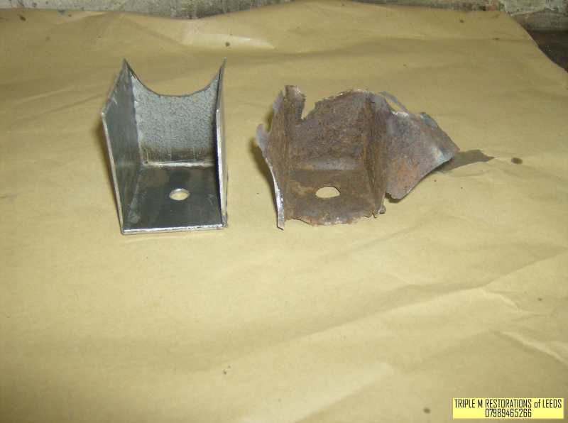
Here you can see the state the old jacking point was in - I jacked the car up on this many times without any problems. I never used the jack alone though & always added an axle stand under the front outrigger.
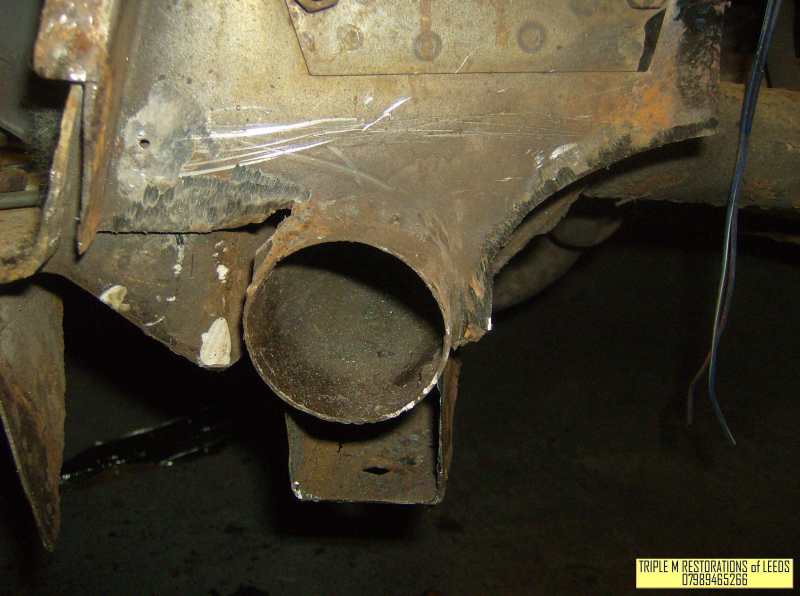
Shot showing the rear outrigger/jacking point � part has had to be cut away to remove rust.
Rear outrigger rebuilt with new metal - old jacking point still there at this point.
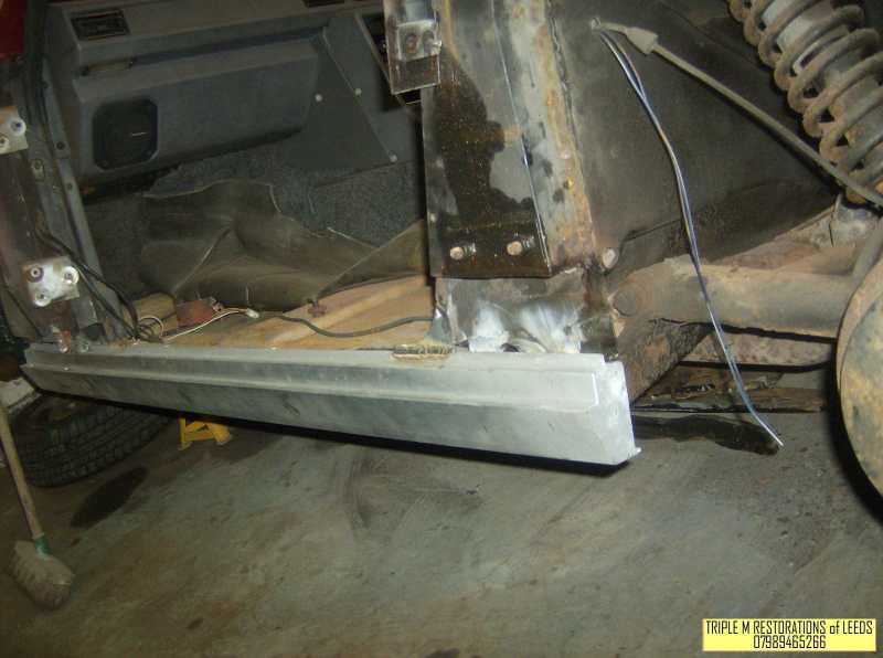
One shiny (well it�s not that shiny actually because it�s galvanised) sill section in place. The old rear jacking point can still be seen just behind it.
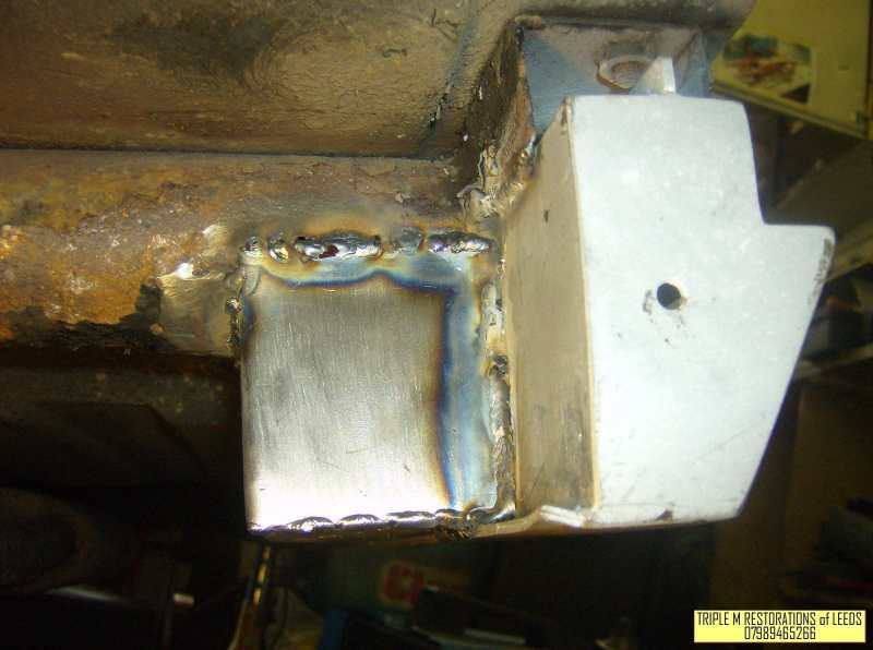
View from the front - showing the new sill & the new shiny jacking point J
Here�s the new sill sprayed up & painted � looking very good.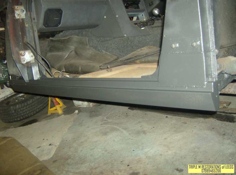
Many thanks for looking - I have loads more which I'll post a bit later on J
I've had the car for just under 2 years & in that time I've ony driven it about 250 miles - mainly to work a couple of summers ago. It was fun to drive & handled well (rear wheel drive) but not that fast (ina straight line at least)! As for the looks well you either like it or hate it (a real marmite car) - I happen to like it but have to admit that it's not the prettiest car ever made! I had money burning a hole in my pocket & bought it with my heart rather than my head. I paid far too much for it but it does have the desirable hard top which just about makes it bearable for winter use - the heater doesn't work very well though so while you'll stay dry (mostly) you'll also freeze! The headlights work, which is important as the mechanisms are s0ds to strip down & put back together apparently. Having got the thing home & having driven it a few times I read somewhere on the web that the Zetec 2 litre engine would bolt directly to the gearbox (using a different flywheel/clutch plate). My friends' cousin just happened to have a 2 litre Mondeo sitting on his mums drive & so the seed was sown. Three weekends later the Zetec engine was sitting in my garage & I made the decision to take the Reliant off the road & have done any work that needed doing to it. The SS1 came in a variety of flavours, the most desirable being the ones with a galvanised chassis & Nissan 1800 turbo power ..... unfortunately my car has neither of these. The lack of galvanising meant that the sills were shot (even though it had 12 months MOT when I bought it) as were the lower parts of the A & B posts. The rest of the chassis, from what I could see of it, appeared sound. I bought a couple of sills (available from Scimitar specialists) & arranged for a couple of chaps, who'd previously made a very good job of restoring a Datsun 120Y coupe & an MGB GT for a couple of workmates, to fit them for me & also to repair as required the A & B posts. They wouldn't be able to take the car for some months due to other commitments so I started stripping the front suspension & brakes down in order to fit uprated polyurethane bushes & to fit bigger vented disc brakes with calipers t hat I mentioned earlier. I did all the suspension/brake work over the Winter of 2008/2009 (& yes it was freezing in the garage & yes every last nut/bolt was seized solid). I had the chassis repairs done in 2009 & had it MOT'd just after all the work had been done. Unfortunately it failed on various things - most of which are electrical in nature. On a glassfibre/plastic bodied car electrical problems are often a result of having a poor earth but these problems seem to have stemmed from a combination of ancient wierd wiring (courtesy of Reliant) & seriously corroded bulb holders/lamps.It's all sorted now & I've beefed up the earth points too just in case
The car as bought:
The front suspension (drivers side) after being stripped & rebuilt - the shocks are inboard on these cars so not visible in this photo.
Passengers side front suspension before I started stripping it - lots of surface rust but no serious corrosion. Corrosion can affect these cars badly - anywhere can rust & there are well documented cases of wishbones cracking around the balljoint mounting with, obviously, disastrous consequences.
Strengthened wishbones - the diagonal bits on each wishbone are new.
A small amount of corrosion at the rear of the chassis - this was sorted when the new sills were fitted & it's all nice & solid again now.
The interior - quite a comfortable place to be if you can live the cacophony of rattles, creaks & squeaks!
New shocks fitted - we're looking down on the engine bay in this shot (engine to the right, radiator to the left, spare wheel (not there) goes in between), the shocks came off an SS1 racer/hillclimber are adjustable & will accept coilover springs if/when I get round to fitting some.
This is how I hope it'll end up looking one day - one of the alloys I got for Chrimbo last year is offered up for effect. The pcd is correct but the offset is all wrong & they foul the brake calipers on the front so I'll need some meaty spacers. They're not exactly high on the list of priorities & will have to wait until I can afford to buy some tyres for them.
I dropped the car off at the welders so that they could replace both sills & do any other repairs to the chassis as necessary.
Here�s the car pre-stripdown � doesn�t look too bad does it?
Here�s a shot of the passengers side sill after the door & both wings have been removed � doesn�t look too good does it?
Oh dear oh dear! Close up of the rear of the sill - showing rust in the sill section & also part way up the B post.
Sill partially stripped off the car � rusty along its entire length L
Shows the rust in the B post more clearly - reel for the seat belt mounts to this!!
Shot showing the front outrigger & jacking point on the passenger�s side - they've started cutting the rot out in this pic. The two bolts at the top of the pic mount the body tub to the chassis.
The front outrigger again but this time with new metal welded in & the old jacking point removed.
Here you can see the state the old jacking point was in - I jacked the car up on this many times without any problems. I never used the jack alone though & always added an axle stand under the front outrigger.
Shot showing the rear outrigger/jacking point � part has had to be cut away to remove rust.
Rear outrigger rebuilt with new metal - old jacking point still there at this point.
One shiny (well it�s not that shiny actually because it�s galvanised) sill section in place. The old rear jacking point can still be seen just behind it.
View from the front - showing the new sill & the new shiny jacking point J
Here�s the new sill sprayed up & painted � looking very good.
Many thanks for looking - I have loads more which I'll post a bit later on J
 11-04-2010, 05:07 PM
#2
15000
Thread Starter
Join Date: Apr 2010
Location: Leeds
Posts: 23
Likes: 0
Received 0 Likes
on
0 Posts
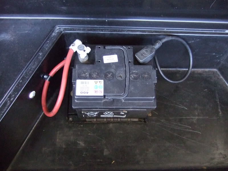
As I'm fitting a larger engine into the SS1 it seems sensible to make as much space as possible in the engine bay. The driver�s side of said engine bay is very crowded as the battery, brake servo/master cylinder & carb/inlet manifold are all situated on this side. Of the three items mentioned above the battery is the easiest to move. The SS1 boot has a false floor hiding a deep well which presumably is needed to carry all the spares/tools required for any sort of journey - it's also known as the "drug compartment"! It's pretty useful really & is an ideal place to re-site the battery. So I've moved the battery from under the bonnet to the boot - not a particularly difficult job, more fiddly & time consuming than anything else.
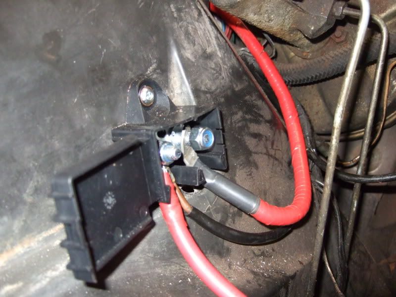
I used a junction box in the engine bay to connect the original battery positive cable to the new length of cable which will run to the back of the car.
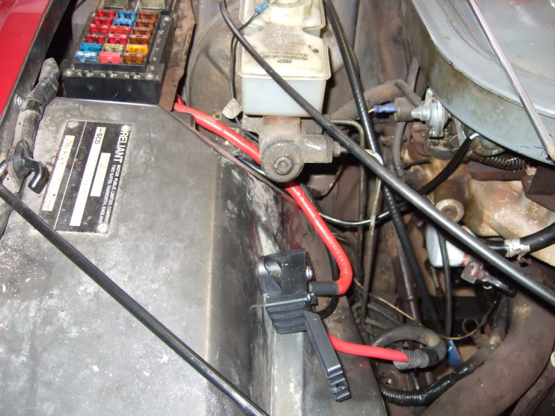
I ran the new cable under the fuse box & through the big bulkhead grommet that the main loom passes through.
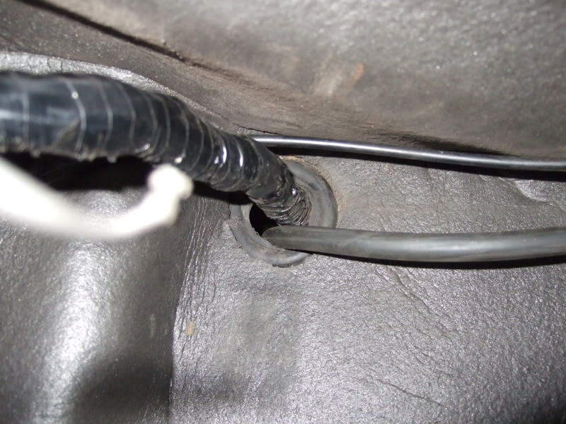
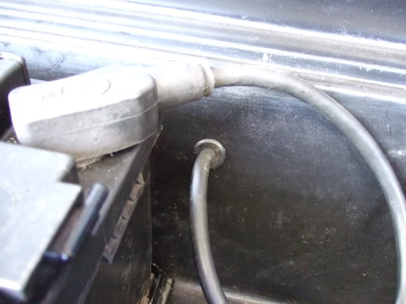
Here's the new cable passing through the bulkhead grommet (you'll have to turn the picture through 90 degrees), I've run it down the bulkhead to the right of the pedals & then along the base of the bulkhead under the pedals & then along the base of the transmission tunnel. I've secured it with plastic p-clips along its whole length.
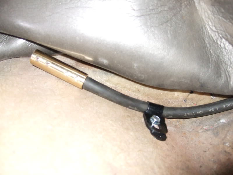
I didn't order enough cable so I've had to join two lengths together - here's the brass connector prior to the next length of cable being fastened to it - the connector comes with a length of heat shrink which I haven't shown but have used despite the bodytub being made of non-conductive glassfibre.
This shot hopefully shows the route of the cable through the car - it also shows the p-clips I've used to fasten the cable down with.
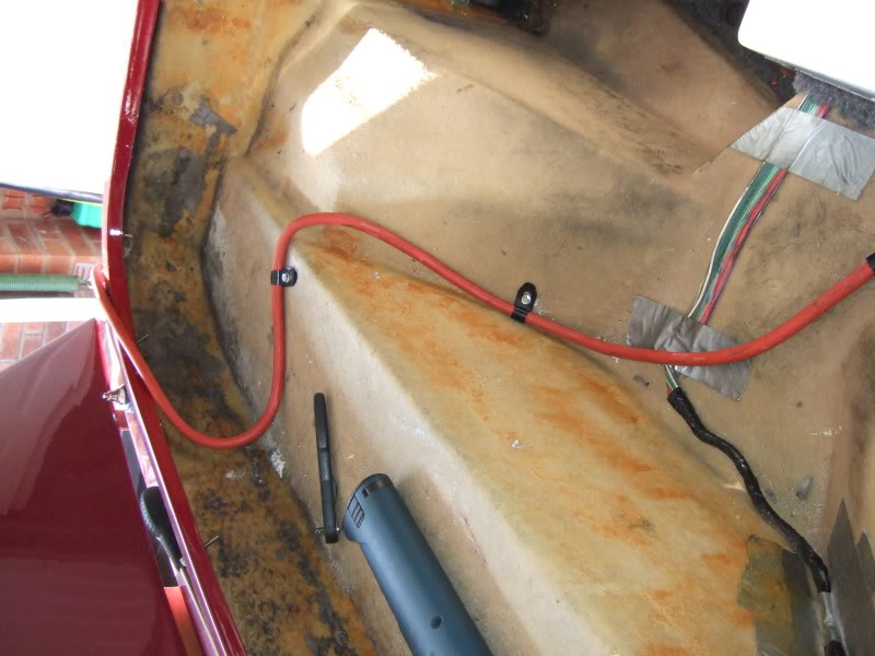
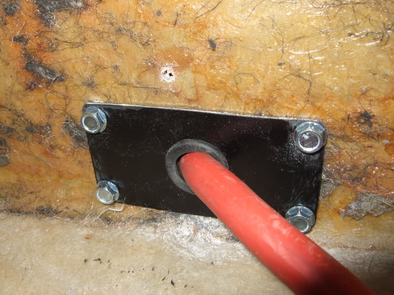
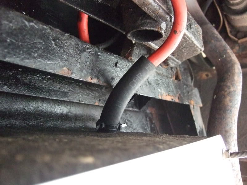
The rear bulkhead caused me a problem as it was too thick for any of the grommets I had, so I made a metal plate (thin enough to take one of the grommets) & passed the cable through this. I then ran the cable down the left hand tank strap, protected it with some heater hose & secured it to the strap with a couple of cable ties.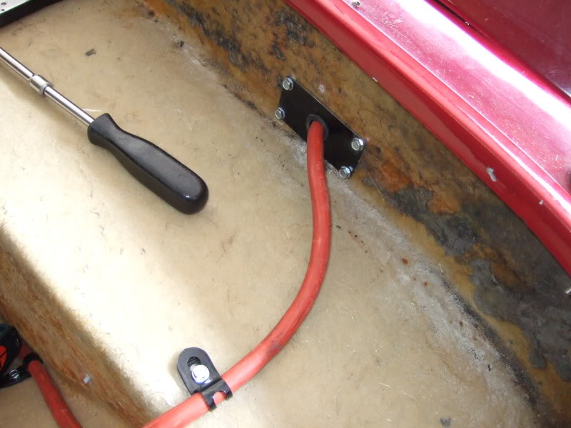
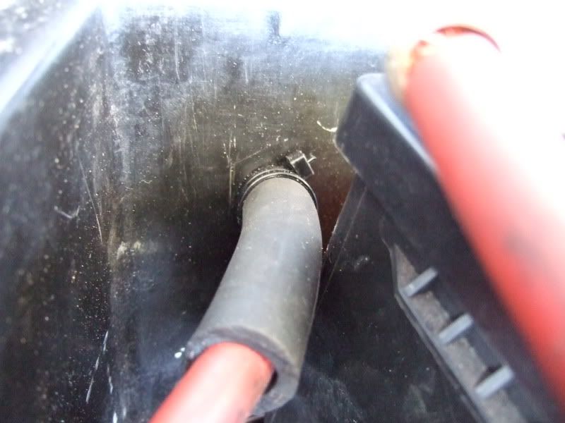
I secured it to the chassis to the rear of the diff with a p-clip & then passed it through a hole I'd drilled in the boot liner. Again I didn't have a suitable grommet so used a length of heater hose to protect the cable (I'm not sure how legal this is come MOT time so I may have to change it later). I've fitted cable ties either side of the boot liner to stop the cable, & hose, pulling through the hole.
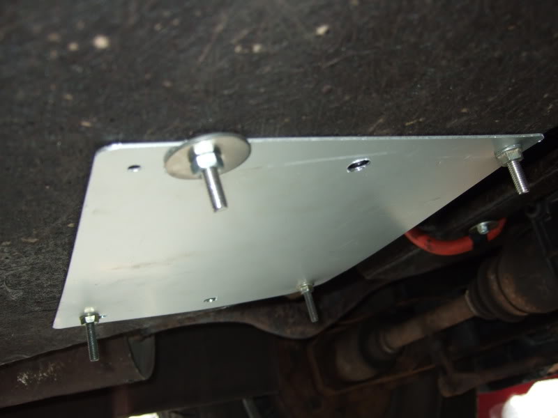
I also made a strengthening plate to fit under the boot liner (ignore all the other holes - I'll learn to "measure twice & cut once" one day. I've bolted it to the car using the bolts I've used to secure the battery tray inside the boot - it's the original Reliant battery tray (as mounted in the engine bay) but with the legs cut off.
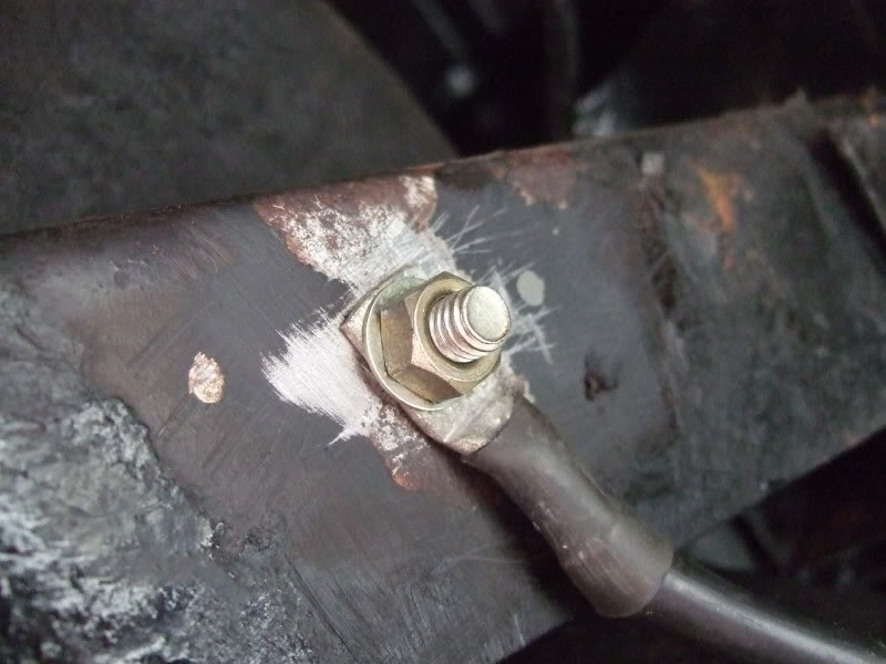
The earth cable was next on the agenda - pretty easy to do & wonder of wonders I found a grommet that I could use - I bolted it to the drivers side rear chassis member after I'd cleaned all the underseal/rust/crap off.
Here it is all finished � I don�t have a picture of it but I�ve since made a false floor for the boot out of wood which hides/protects the battery.
I used a junction box in the engine bay to connect the original battery positive cable to the new length of cable which will run to the back of the car.
I ran the new cable under the fuse box & through the big bulkhead grommet that the main loom passes through.
Here's the new cable passing through the bulkhead grommet (you'll have to turn the picture through 90 degrees), I've run it down the bulkhead to the right of the pedals & then along the base of the bulkhead under the pedals & then along the base of the transmission tunnel. I've secured it with plastic p-clips along its whole length.
I didn't order enough cable
This shot hopefully shows the route of the cable through the car - it also shows the p-clips I've used to fasten the cable down with.
The rear bulkhead caused me a problem as it was too thick for any of the grommets I had, so I made a metal plate (thin enough to take one of the grommets) & passed the cable through this. I then ran the cable down the left hand tank strap, protected it with some heater hose & secured it to the strap with a couple of cable ties.
I secured it to the chassis to the rear of the diff with a p-clip & then passed it through a hole I'd drilled in the boot liner. Again I didn't have a suitable grommet so used a length of heater hose to protect the cable (I'm not sure how legal this is come MOT time so I may have to change it later). I've fitted cable ties either side of the boot liner to stop the cable, & hose, pulling through the hole.
I also made a strengthening plate to fit under the boot liner (ignore all the other holes - I'll learn to "measure twice & cut once" one day. I've bolted it to the car using the bolts I've used to secure the battery tray inside the boot - it's the original Reliant battery tray (as mounted in the engine bay) but with the legs cut off.
The earth cable was next on the agenda - pretty easy to do & wonder of wonders I found a grommet that I could use - I bolted it to the drivers side rear chassis member after I'd cleaned all the underseal/rust/crap off.
Here it is all finished � I don�t have a picture of it but I�ve since made a false floor for the boot out of wood which hides/protects the battery.
11-04-2010, 05:25 PM
#3
15000
Thread Starter
Join Date: Apr 2010
Location: Leeds
Posts: 23
Likes: 0
Received 0 Likes
on
0 Posts
I'd been told that the SS1 engine mount brackets would fit the Zetec block but not without some modification. I wanted to see what modifications were needed for myself & I also wanted to get the mounting brackets modified before trying to fit the Zetec engine - so that I wasn't pulling the engine in & out all the time while I modified the brackets that are currently fitted to the CVH engine (they're in a lousy state so replacing them isn't a bad idea anyway).
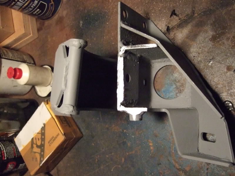
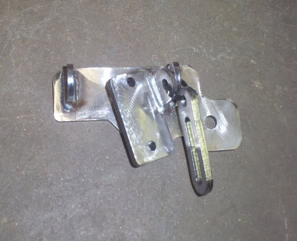
I bought some mounting brackets through a Scimweb forum member & they arrived in excellent condition - already cleaned & primed for painting!
It looked as if the water pump side mounting would fit the pre-tapped holes on the engine block but the alternator mount was in the way so I had to cut this off. I�ve keep the alternator mount as I'm hoping to make se of it later in the build.
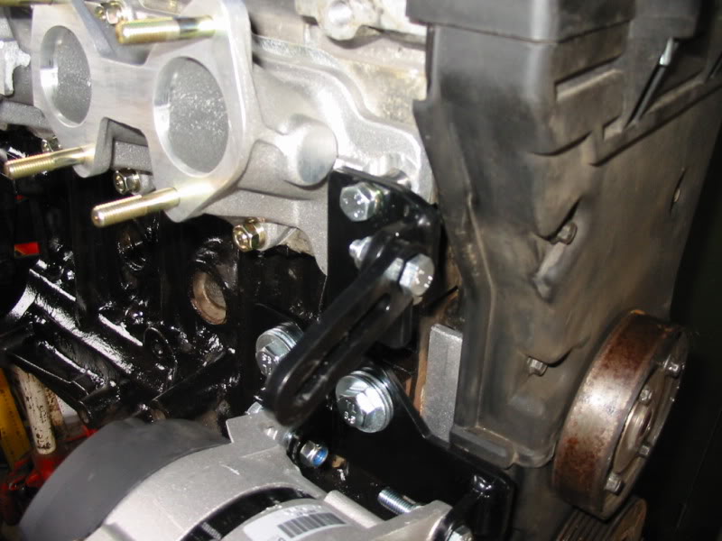
Here�s the mounting bracket fitted to the Zetec block with no problems at all -all the holes line up fine & there's plenty of clearance round the water pump outlet for the radiator hose �� which is good !
!
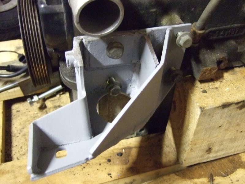
I tried the other bracket which didn't need modifying. Unfortunately only 3 out of the 4 holes lined up. The 4th hole wasn't a million miles away & I attacked it with a file & eventually got it to fit.
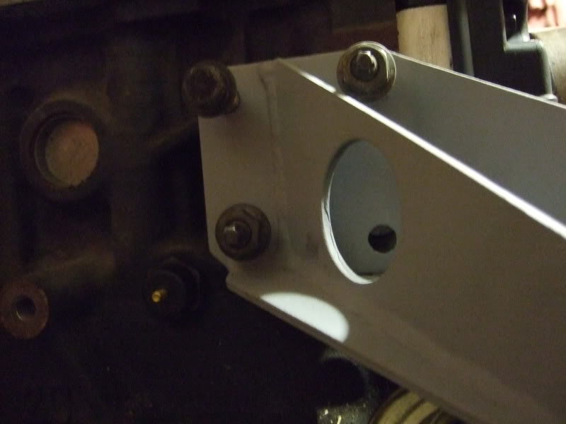
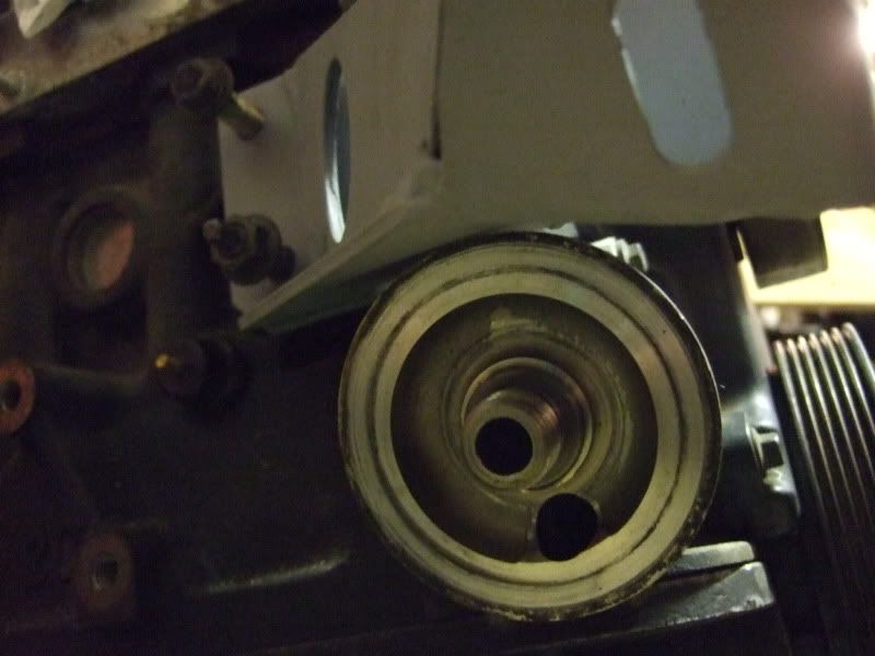
There�s very little clearance (none that I can see) between the bracket & the oil filter housing so it looks as if I'll be using a remote oil filter ..... which is what I was intending to do anyway.
As for the alternator well a search of the kitcar manufacturers (many of whom fit the Zetec engine in their cars) turned up Tiger Racing & this alternator mount. I'm possibly going to buy one but now I'm hoping to use the part I cut off the engine mount earlier!
I bought some mounting brackets through a Scimweb forum member & they arrived in excellent condition - already cleaned & primed for painting!
It looked as if the water pump side mounting would fit the pre-tapped holes on the engine block but the alternator mount was in the way so I had to cut this off. I�ve keep the alternator mount as I'm hoping to make se of it later in the build.
Here�s the mounting bracket fitted to the Zetec block with no problems at all -all the holes line up fine & there's plenty of clearance round the water pump outlet for the radiator hose �� which is good
I tried the other bracket which didn't need modifying. Unfortunately only 3 out of the 4 holes lined up. The 4th hole wasn't a million miles away & I attacked it with a file & eventually got it to fit.
There�s very little clearance (none that I can see) between the bracket & the oil filter housing so it looks as if I'll be using a remote oil filter ..... which is what I was intending to do anyway.
As for the alternator well a search of the kitcar manufacturers (many of whom fit the Zetec engine in their cars) turned up Tiger Racing & this alternator mount. I'm possibly going to buy one but now I'm hoping to use the part I cut off the engine mount earlier!


 11-04-2010, 05:53 PM
#6
15000
Thread Starter
Join Date: Apr 2010
Location: Leeds
Posts: 23
Likes: 0
Received 0 Likes
on
0 Posts
During this project I've never given myself any time limits/deadlines. I wanted to enjoy myself during it not beat myself up & stress about every time there was a delay or something went wrong. Having said that I really did want the old engine out & the new one in before the end of 2009. So with the help of a borrowed engine hoist & 3 willing/unwilling friends I removed the smoky old cvh engine so that I could clean up the engine bay in readiness for the shiny, new (well still quite old actually) 2 litre Zetec
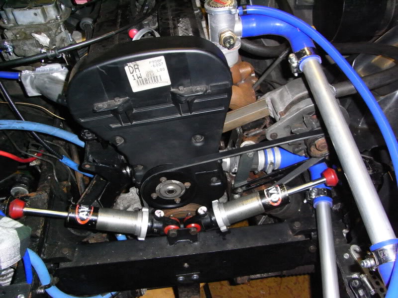
It all went pretty smoothly really. We did think we were going to have problems clearing the front cross-member - the one the inboard shocks bolt to - but we then realised that it was removable (thank you Reliant!) which made the job much easier. Once it was out of the way it was all plain sailing & engine was out in about 15 mins. Biggest job after that was getting rid of the old exhaust. At the time I wanted to trial fit the new engine but there really wasn’t any time (or light) left so I'm glad we called it a day when we did. The engine bay was filthy so I spent a couple of days cleaning & painting it. I used Gunk (engine degreaser) which I'd highly recommend
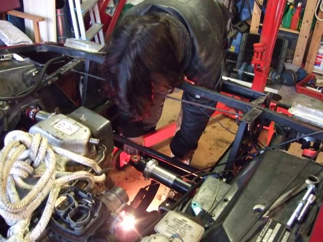
Here we can see my friend Mohammed (he’s car mad!) bent double over the front of the car spannering away like a good ‘un!
Another shot of Mohammed still spannering away On the same bolt no doubt)!
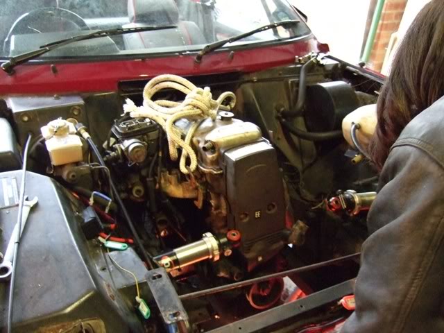
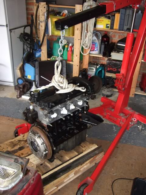
Here’s a shot of the CVH lump – rope for hoisting duties is attached but the hoist isn’t. No shots of the engine being actually hoisted I’m afraid as it took all 4 of us to guide it out of the engine bay! Mohammed at the front again – he get’s everywhere!
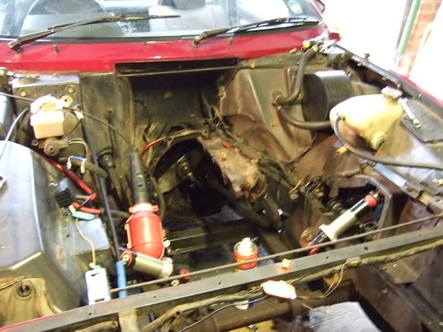
Engine removed & this is the hole left behind - after 24 years (now 25!) on/off the road it was a wee bit grimy!
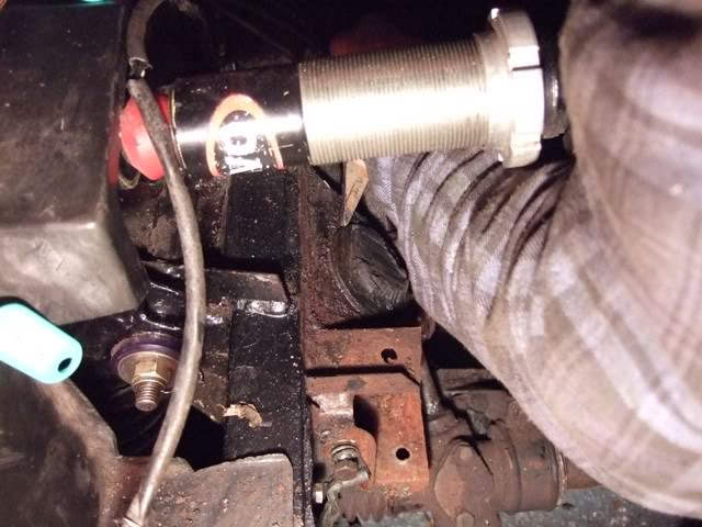
This rather boring shot shows the threaded hole left by the passengers side engine mount rubber which was easily removed with an oil filter chain wrench. Unfortunately the driver’s side mount was seized so had to be cut away leaving the backing plate (which has the stud that screws into the threaded hole welded to it).
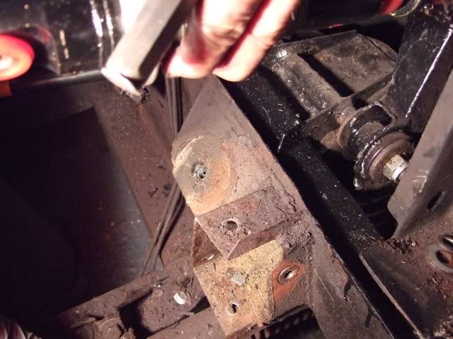
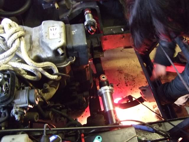
Here’s a shot of yours truly (well that’s my arm anyway) applying a bit of brute force & ignorance courtesy of a cold chisel & lump hammer to the aforementioned backing plate. It gave up without too much of a fight leaving me with a totally engineless car. Which at least made it easy to push in & out of the garage!
J
It all went pretty smoothly really. We did think we were going to have problems clearing the front cross-member - the one the inboard shocks bolt to - but we then realised that it was removable (thank you Reliant!) which made the job much easier. Once it was out of the way it was all plain sailing & engine was out in about 15 mins. Biggest job after that was getting rid of the old exhaust. At the time I wanted to trial fit the new engine but there really wasn’t any time (or light) left so I'm glad we called it a day when we did. The engine bay was filthy so I spent a couple of days cleaning & painting it. I used Gunk (engine degreaser) which I'd highly recommend
Here we can see my friend Mohammed (he’s car mad!) bent double over the front of the car spannering away like a good ‘un!
Another shot of Mohammed still spannering away On the same bolt no doubt)!
Here’s a shot of the CVH lump – rope for hoisting duties is attached but the hoist isn’t. No shots of the engine being actually hoisted I’m afraid as it took all 4 of us to guide it out of the engine bay! Mohammed at the front again – he get’s everywhere!
Engine removed & this is the hole left behind - after 24 years (now 25!) on/off the road it was a wee bit grimy!
This rather boring shot shows the threaded hole left by the passengers side engine mount rubber which was easily removed with an oil filter chain wrench. Unfortunately the driver’s side mount was seized so had to be cut away leaving the backing plate (which has the stud that screws into the threaded hole welded to it).
Here’s a shot of yours truly (well that’s my arm anyway) applying a bit of brute force & ignorance courtesy of a cold chisel & lump hammer to the aforementioned backing plate. It gave up without too much of a fight leaving me with a totally engineless car. Which at least made it easy to push in & out of the garage!
J
Last edited by pauluspaolo; 11-04-2010 at 07:01 PM.
11-04-2010, 06:18 PM
#7
15000
Thread Starter
Join Date: Apr 2010
Location: Leeds
Posts: 23
Likes: 0
Received 0 Likes
on
0 Posts
As I wanted to get the new engine in before the end of 2009 I spent New Years Eve working on the car with a couple of friends, the intention being to finally get the Zetec in. I�d already made an unsuccessful attempt (with another friend) earlier in the week so this was my last chance (literally) before the end of 2009! The only reason for wanting to get the new engine in was that I thought it�d be nice to finish the year off with a fairly major part of the project accomplished. This time round we were successful in getting the engine in but, needless to say, there are still a few problems to sort out. The main problem being that due to the front crossmember (the one holding the steering rack which isn't removeable) getting in the way the engine wouldn�t go in with the sump fitted. Once we�d removed the sump it went in without too much drama & it was nice to see the engine mounts line up. The problem then was that I couldn�t refit the sump with the engine in place because it still catches on that (bloody) front crossmember! If I had an extra inch or so of clearance it�d fit fine! At the moment the sump's away being modified by a retired engineer friend of mine.
Earlier in the year (2009) I'd bought a fuel injection manifold that was originally used in a Ginetta G20 (fitted with an 1800 Zetec) unfortunately there�s just not enough room between the engine & inner wing I'm not sure what I�m going to do now but I may try & use the CVH inlet manifold/re-jetted carb with an adaptor plate or I could maybe go down the bike carb route.
Here�s the engine waiting to go in � not too much to say really other than it�s complete at this stage with sump attached:
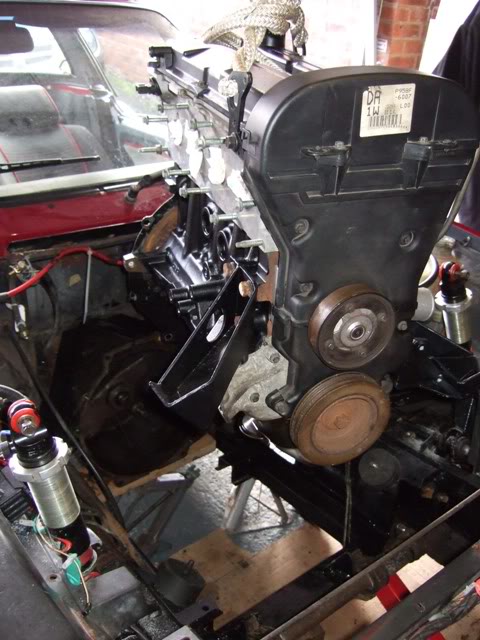
Here�s the engine being lowered into position � sump off at this stage:
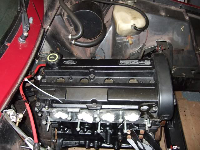
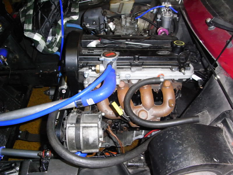
Here�s the best shot I have of the engine fitted � sorry it�s a bit naff but we were all completely frozen by this stage & more than ready to stop & thaw out indoors with a nice cuppa:
Earlier in the year (2009) I'd bought a fuel injection manifold that was originally used in a Ginetta G20 (fitted with an 1800 Zetec) unfortunately there�s just not enough room between the engine & inner wing
I'm not sure what I�m going to do now but I may try & use the CVH inlet manifold/re-jetted carb with an adaptor plate or I could maybe go down the bike carb route. Here�s the engine waiting to go in � not too much to say really other than it�s complete at this stage with sump attached:
Here�s the engine being lowered into position � sump off at this stage:
Here�s the best shot I have of the engine fitted � sorry it�s a bit naff but we were all completely frozen by this stage & more than ready to stop & thaw out indoors with a nice cuppa:
Trending Topics
11-04-2010, 06:57 PM
#8
15000
Thread Starter
Join Date: Apr 2010
Location: Leeds
Posts: 23
Likes: 0
Received 0 Likes
on
0 Posts
To bring everyhing up to date the most recent thing(s) I've done to the car have been to fit a roll-over bar & fit a pair of MX5 seats To make more room in the car I removed the seats. The bar went in the car no problem & using some pointers I'd printed off the Scimweb forum (a mine of information) I started the job! The first mistake I made was that I didn't mark where the feet of the bar went when the carpet was in place. So once I'd fitted & bolted the bar in place without the carpet in the car I realised that it'd all have to come out again so that I could refit/mark/cut the carpet!! Did I feel a numpty? Yes I did !
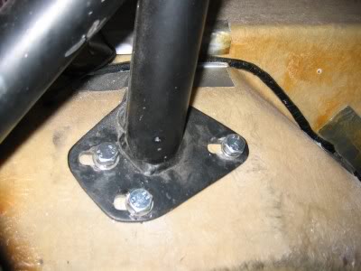
On some (all?) of the galvanised SS1's there are captive nuts, for the roll bar feet bolts, built into the chassis. As mine is a non-galvanised car I wasn't sure if these captive nuts would be present or not. It turns out that they aren't fitted to my car so I had to drill some 10mm holes & make a quick trip to Screwfix (fortunately there's a branch close to my house) to buy some bolts (& nyloc nuts) suitable for the job. Eventually I got the bar bolted in place & it feels solid. I'm told that welding it in position would be better but I'm not sure how I'd do this given that there's a layer of glass fibre between the rollover bar feet & the actual chassis & I'm not taking the car to bits any more than it is already! The bar is also held in place by three M8 bolts at the B-post so it�s held in position by 12 bolts (6 per side) in total. It feels totally solid & should increase the strength/rigidity of the car quite a bit I think. I have been told that the strength of the actual bar can be increased by welding a diagonal bar across it but I�m not sure this is really necessary.
Anyway here are a few pictures of the job � the last one shows the finished installation.
The first pic shows the roll bar foot & the three M10 bolts that hold it in position. I�ve used thick washers/spreader plates behind to secure them. Access was a complete pig & I had to remove the rear shock absorbers to give me more room � even then the rear suspension arms got in the way & I ended up using just about every extension I had in my socket set to reach the nuts!!
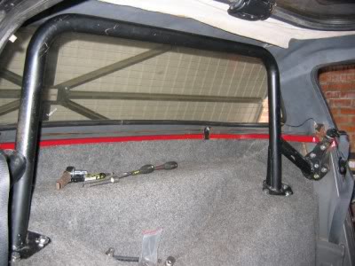
This pic shows the roll bar in position - all holes drilled & partly bolted in. I then realised that it'd have to come out again so that I could fit/mark/cut the carpet.
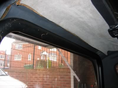
This photo shows the clearance between the roll bar & inside of the hard top (it also shows that my hard top needs retrimming - yet another job). Clearance with the hard top fitted is fine, so it should be ok with the soft top fitted, but I'll just have to wait & see. The soft top's pretty worn out & could really do with replacing so I'll probably end up using the car with the hard top fitted most of the time.
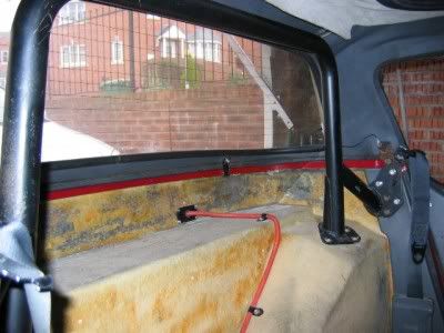
And here we have the finished installation - carpet fitted & cut, roll bar in position & all bolts tightened up. I like the way it looks & it feels proper, & I mean PROPER, solid & I'm chuffed with it. I'm not sure I'd want to do the job again anytime soon though!!
Opinions welcome as always.
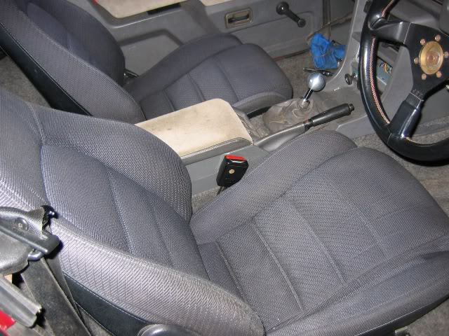
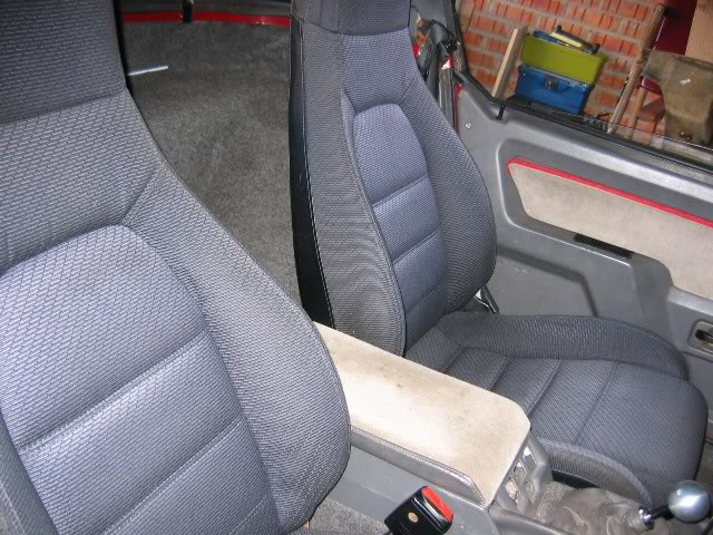
I also wanted to fit a pair of MX5 seats I'd got off Retro-Rides & I recently spent a day hack sawing, drilling, tapping, sweating, straining & swearing as I adapted the Reliant seat runners to fit them - the Reliant seat runners have the seat belt mounting points built into them so it best to use them if I could! My idea being to make some adaptor plates that I could bolt to the MX5 seat bases using the M8 holes already tapped into them. I'd then bolt the Reliant runners onto the plates into which I�d tapped another M8 hole. I didn't take any photo's of the adaptors I'm afraid (sorry about that) but they seem to do the job well enough. They were fiddly & time consuming to make - the worst part being hack sawing through the 10mm plate! Both seats feel very secure & still move forwards & backwards (though the drivers side seat is a little reluctantl to move). The seats themselves are much comfier & more supportive than the originals (which were flat, unsupportive & knackered) but they also felt overstuffed, almost as if you were sitting on top of them rather than in them if that makes any sense? So I removed the seats & then the seat covers & attacked the seat foam with an electric carving knife (as you do!) in order to try & reduce the height of the seat cushion. Despite being a bit drastic it seems to have worked well enough & both seats (the drivers side especially) feel much more �buckety� whilst still being comfortable & supportive. The main problem is that the seat bases are a bit deeper than the original Reliant ones so they sit a bit higher, This isn�t really a problem for me & Gillian as we�re both 5�7�ish but it probably will be a problem for anyone much taller than us - having said that my 5'10" friend can get comfortable in the car so maybe it isn't a problem at all!? Even so I can see me getting the seat rails lowered at some stage in the future which means doing a bit of cutting & welding & then getting the floor re-fibreglassed! It�s not a huge job (apparently), & plenty of people who've fitted aftermarket seats have already done it, but it�s not really something I want to start right now.
So that's the interior more or less sorted, next on the agenda is to try & get the engine running. I need to pull it out again so that I can fit a new clutch release bearing - I should have fitted one when the engine was out but, like a complete plonker, I forgot! The lack of a sump is still a major problem but I�m hoping that my friend will get it sorted soon! Then I'm probably going to have to leave the car for a bit until I can get the funds together for a fuel pump, carb(s)/manifold, megajolt ecu, starter motor, alternator mount & alternator, exhaust etc etc etc!
I'm getting married at the end of July , and then I�m off on honeymoon for 2 weeks, so it looks as if life will get in the way of the project for a while.
Anyway here are a couple of not very good pics of the seats installed.
On some (all?) of the galvanised SS1's there are captive nuts, for the roll bar feet bolts, built into the chassis. As mine is a non-galvanised car I wasn't sure if these captive nuts would be present or not. It turns out that they aren't fitted to my car so I had to drill some 10mm holes & make a quick trip to Screwfix (fortunately there's a branch close to my house) to buy some bolts (& nyloc nuts) suitable for the job. Eventually I got the bar bolted in place & it feels solid. I'm told that welding it in position would be better but I'm not sure how I'd do this given that there's a layer of glass fibre between the rollover bar feet & the actual chassis & I'm not taking the car to bits any more than it is already! The bar is also held in place by three M8 bolts at the B-post so it�s held in position by 12 bolts (6 per side) in total. It feels totally solid & should increase the strength/rigidity of the car quite a bit I think. I have been told that the strength of the actual bar can be increased by welding a diagonal bar across it but I�m not sure this is really necessary.
Anyway here are a few pictures of the job � the last one shows the finished installation.
The first pic shows the roll bar foot & the three M10 bolts that hold it in position. I�ve used thick washers/spreader plates behind to secure them. Access was a complete pig & I had to remove the rear shock absorbers to give me more room � even then the rear suspension arms got in the way & I ended up using just about every extension I had in my socket set to reach the nuts!!
This pic shows the roll bar in position - all holes drilled & partly bolted in. I then realised that it'd have to come out again so that I could fit/mark/cut the carpet.
This photo shows the clearance between the roll bar & inside of the hard top (it also shows that my hard top needs retrimming - yet another job). Clearance with the hard top fitted is fine, so it should be ok with the soft top fitted, but I'll just have to wait & see. The soft top's pretty worn out & could really do with replacing so I'll probably end up using the car with the hard top fitted most of the time.
And here we have the finished installation - carpet fitted & cut, roll bar in position & all bolts tightened up. I like the way it looks & it feels proper, & I mean PROPER, solid & I'm chuffed with it. I'm not sure I'd want to do the job again anytime soon though!!
Opinions welcome as always.
I also wanted to fit a pair of MX5 seats I'd got off Retro-Rides & I recently spent a day hack sawing, drilling, tapping, sweating, straining & swearing as I adapted the Reliant seat runners to fit them - the Reliant seat runners have the seat belt mounting points built into them so it best to use them if I could! My idea being to make some adaptor plates that I could bolt to the MX5 seat bases using the M8 holes already tapped into them. I'd then bolt the Reliant runners onto the plates into which I�d tapped another M8 hole. I didn't take any photo's of the adaptors I'm afraid (sorry about that) but they seem to do the job well enough. They were fiddly & time consuming to make - the worst part being hack sawing through the 10mm plate! Both seats feel very secure & still move forwards & backwards (though the drivers side seat is a little reluctantl to move). The seats themselves are much comfier & more supportive than the originals (which were flat, unsupportive & knackered) but they also felt overstuffed, almost as if you were sitting on top of them rather than in them if that makes any sense? So I removed the seats & then the seat covers & attacked the seat foam with an electric carving knife (as you do!) in order to try & reduce the height of the seat cushion. Despite being a bit drastic it seems to have worked well enough & both seats (the drivers side especially) feel much more �buckety� whilst still being comfortable & supportive. The main problem is that the seat bases are a bit deeper than the original Reliant ones so they sit a bit higher, This isn�t really a problem for me & Gillian as we�re both 5�7�ish but it probably will be a problem for anyone much taller than us - having said that my 5'10" friend can get comfortable in the car so maybe it isn't a problem at all!? Even so I can see me getting the seat rails lowered at some stage in the future which means doing a bit of cutting & welding & then getting the floor re-fibreglassed! It�s not a huge job (apparently), & plenty of people who've fitted aftermarket seats have already done it, but it�s not really something I want to start right now.
So that's the interior more or less sorted, next on the agenda is to try & get the engine running. I need to pull it out again so that I can fit a new clutch release bearing - I should have fitted one when the engine was out but, like a complete plonker, I forgot! The lack of a sump is still a major problem but I�m hoping that my friend will get it sorted soon! Then I'm probably going to have to leave the car for a bit until I can get the funds together for a fuel pump, carb(s)/manifold, megajolt ecu, starter motor, alternator mount & alternator, exhaust etc etc etc!
I'm getting married at the end of July
, and then I�m off on honeymoon for 2 weeks, so it looks as if life will get in the way of the project for a while.Anyway here are a couple of not very good pics of the seats installed.
11-04-2010, 07:51 PM
#9
Congratulations mate, looking good.... many a summer has been spent playing with my friends Scimitar (or how ever the fuck its spelt!) always quite liked the ss1's especially the really late one with the 1.4 k series fitted....
Bets of luck with it
Rob,
Bets of luck with it
Rob,
25-04-2012, 01:24 PM
#10
15000
Thread Starter
Join Date: Apr 2010
Location: Leeds
Posts: 23
Likes: 0
Received 0 Likes
on
0 Posts
Ages since I last updated this � not sure it�s entirely relevant on a Ford forum but it does use a Ford engine, gearbox & rear axle/diff so here goes!
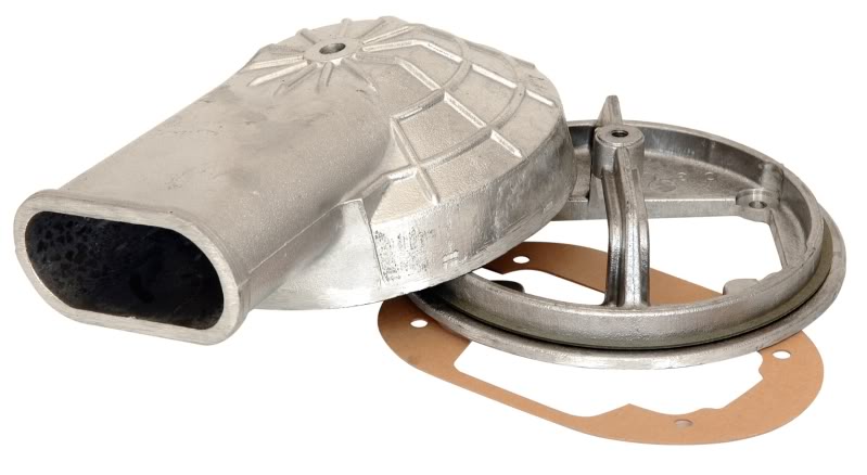
As a most of you probably know t he thermostat housing on the Zetec engine is situated at the back of the cylinder head � this is fine in a front wheel drive layout but not so good in a rear wheel drive layout. It means there�s a long length of pipe from the thermostat to the radiator & it means that changing the thermostat can be awkward due to the closeness of the bulkhead � although there�s a recess on the SS1 which means that while it isn�t pressed up against the bulkhead it is buried under the base of the windscreen! As Zetec conversions/installations become more popular in things like Mk1/MK2 Escorts, Cortina�s, Capri�s etc parts are becoming available to make these conversions easier. One of these parts is the Raceline water rail which moves the thermostat housing from the rear of the engine to the side/front. This also reduces the length of pipe needed from the thermostat housing to the radiator - though it�s still quite a long run in the SS1 because the radiator's miles away from the engine & the inlet is on the far side of the radiator.
Anyway the upshot of all this is that to make my life easier (& my bank account much slimmer) I�ve bought & fitted a Raceline water rail � it�s a thing of beauty, looks like it's part of the engine & fitted perfectly. Unfortunately it means that my very nice tubular exhaust manifold won�t fit so that�s more money to be spent later on & the pile of parts to list on Ebay grows ever larger!
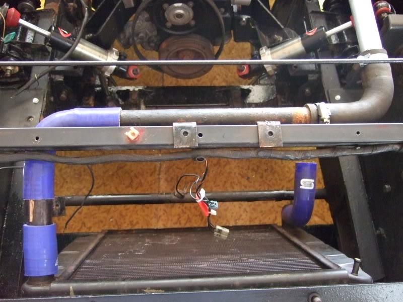
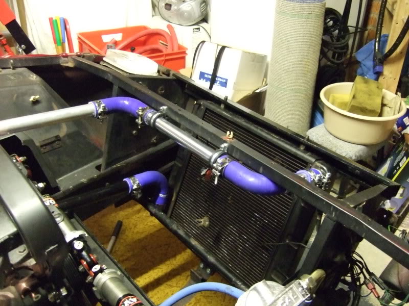
As I say fitting the water rail has simplified the cooling system somewhat & I�ve started a trial layout of what bit of pipe goes where. I�m going to use blue silicone hose mated to metal (a combination of steel & alloy) coolant pipes. It should work well I think despite all the joints & jubilee clips (8).
I�ve also bought various other parts, which I've yet to fit, such as rear trailing arms, an electric fuel pump, twin choke Weber carb & manifold & finally a Megajolt ecu � this last item is essential & makes sure the sparks go where they�re supposed to go, at the time they�re supposed to go there! The biggest job out of all that lot will be fitting the rear trailing arms (though I�m not looking forward to wiring up the Megajolt either) & this means that I�ll finally have to bite the bullet & start stripping the rear of the car down. This is a pretty difficult job by all accounts & it�s not one that I�ve been looking forward to at all ! Fitting it all should keep me busy for the rest of the year!
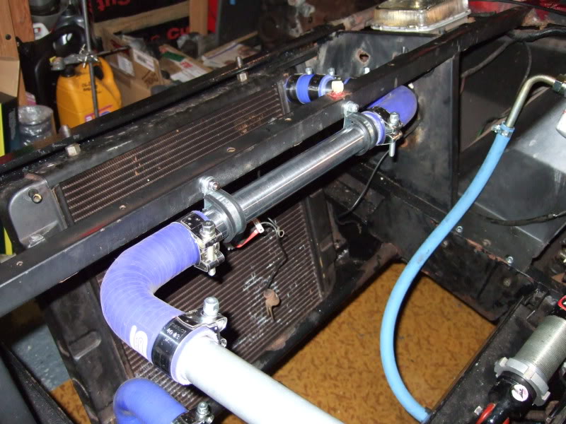
The water rail fitted.
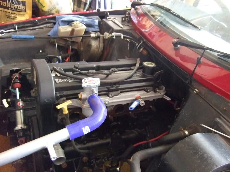
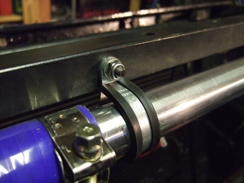
Looking forward towards the radiator which shows the run of the pipe (as well as all the joints) � I�ve replaced the black rubber elbow with a blue silicone one since this photo was taken.
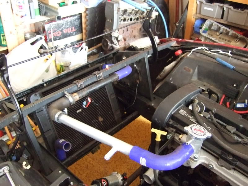
Looking down on the pipe run from above � the black metal pipe in the middle is part of the original SS1 cooling system & needs cleaning up (or replacing) & painting. You can get stainless steel coolant pipes for the SS1 but they're pretty expensive.
Thanks for reading
As a most of you probably know t he thermostat housing on the Zetec engine is situated at the back of the cylinder head � this is fine in a front wheel drive layout but not so good in a rear wheel drive layout. It means there�s a long length of pipe from the thermostat to the radiator & it means that changing the thermostat can be awkward due to the closeness of the bulkhead � although there�s a recess on the SS1 which means that while it isn�t pressed up against the bulkhead it is buried under the base of the windscreen! As Zetec conversions/installations become more popular in things like Mk1/MK2 Escorts, Cortina�s, Capri�s etc parts are becoming available to make these conversions easier. One of these parts is the Raceline water rail which moves the thermostat housing from the rear of the engine to the side/front. This also reduces the length of pipe needed from the thermostat housing to the radiator - though it�s still quite a long run in the SS1 because the radiator's miles away from the engine & the inlet is on the far side of the radiator.
Anyway the upshot of all this is that to make my life easier (& my bank account much slimmer) I�ve bought & fitted a Raceline water rail � it�s a thing of beauty, looks like it's part of the engine & fitted perfectly. Unfortunately it means that my very nice tubular exhaust manifold won�t fit so that�s more money to be spent later on & the pile of parts to list on Ebay grows ever larger!
As I say fitting the water rail has simplified the cooling system somewhat & I�ve started a trial layout of what bit of pipe goes where. I�m going to use blue silicone hose mated to metal (a combination of steel & alloy) coolant pipes. It should work well I think despite all the joints & jubilee clips (8).
I�ve also bought various other parts, which I've yet to fit, such as rear trailing arms, an electric fuel pump, twin choke Weber carb & manifold & finally a Megajolt ecu � this last item is essential & makes sure the sparks go where they�re supposed to go, at the time they�re supposed to go there! The biggest job out of all that lot will be fitting the rear trailing arms (though I�m not looking forward to wiring up the Megajolt either) & this means that I�ll finally have to bite the bullet & start stripping the rear of the car down. This is a pretty difficult job by all accounts & it�s not one that I�ve been looking forward to at all
The water rail fitted.
Looking forward towards the radiator which shows the run of the pipe (as well as all the joints) � I�ve replaced the black rubber elbow with a blue silicone one since this photo was taken.
Looking down on the pipe run from above � the black metal pipe in the middle is part of the original SS1 cooling system & needs cleaning up (or replacing) & painting. You can get stainless steel coolant pipes for the SS1 but they're pretty expensive.
Thanks for reading
25-04-2012, 01:27 PM
#11
15000
Thread Starter
Join Date: Apr 2010
Location: Leeds
Posts: 23
Likes: 0
Received 0 Likes
on
0 Posts
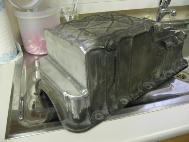
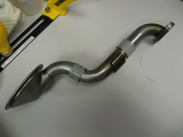
More - before getting married & disappearing off on honeymoon to Kenya (July 2010) I managed to find a local chap called Jamie who was able to tig weld up my much hacked about & modified sump. Unfortunately the pick-up pipe didn't fit so I had to hack a bit more out of it & then get Jamie to weld a bulge over the resulting hole! I also had to modify the pick-up pipe to reduce the overall length/depth of it. I’m happy to report that it all fits fine & is now bolted up into position.
This is the cut & shut pick-up pipe prior to welding:
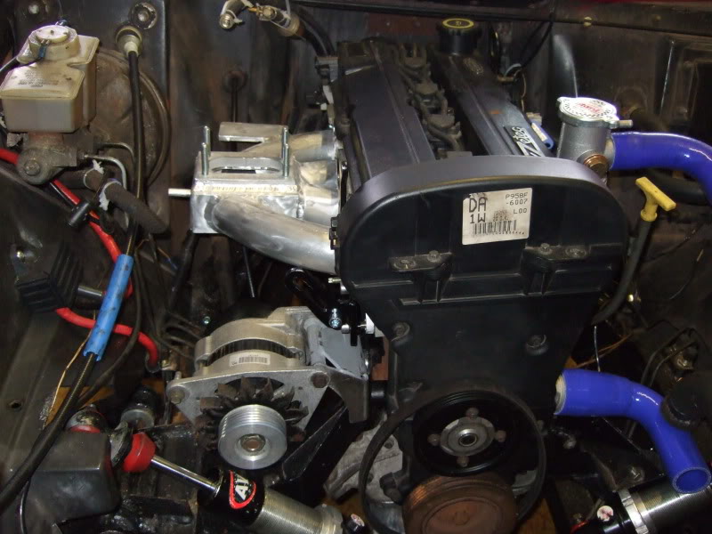
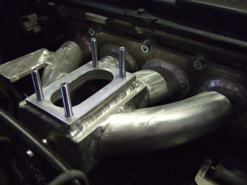
Some time before my wedding I ordered an inlet manifold from Usher Engineering – this has been developed for banger racing (where fuel injection isn’t allowed) & is designed to take a single twin choke 32/36 Weber carburettor. I was told that the manifold should arrive before I went on honeymoon but, unfortunately, it didn’t. When I got back there was a note from DHL saying that it had been left with a neighbour, so I trotted off & picked it up from them, who’d been holding onto it for the best part of two weeks. It wasn’t the cheapest thing in the world but I have to say that it’s beautifully made & fits a treat.
Anyway here are a few pics of the thing in position:
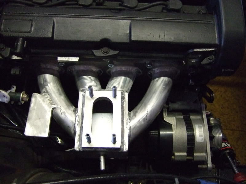
I have a suitable carb but haven’t fitted it yet as the engine has to come out so that I can change the clutch release bearingL! Also I’ve no idea of the history of the carb so that could do with a stripdown & clean …… then I’ll have to try & make up some sort of throttle linkage. So there’s still a huge amount left to do on the car.
One of the pics above shows the alternator mount below the inlet manifold – this still needs welding up so I’ll probably try & get that done when the engine’s out of the car. I’m not sure when any of this will happen though!
J
This is the cut & shut pick-up pipe prior to welding:
Some time before my wedding I ordered an inlet manifold from Usher Engineering – this has been developed for banger racing (where fuel injection isn’t allowed) & is designed to take a single twin choke 32/36 Weber carburettor. I was told that the manifold should arrive before I went on honeymoon but, unfortunately, it didn’t. When I got back there was a note from DHL saying that it had been left with a neighbour, so I trotted off & picked it up from them, who’d been holding onto it for the best part of two weeks. It wasn’t the cheapest thing in the world but I have to say that it’s beautifully made & fits a treat.
Anyway here are a few pics of the thing in position:
I have a suitable carb but haven’t fitted it yet as the engine has to come out so that I can change the clutch release bearingL! Also I’ve no idea of the history of the carb so that could do with a stripdown & clean …… then I’ll have to try & make up some sort of throttle linkage. So there’s still a huge amount left to do on the car.
One of the pics above shows the alternator mount below the inlet manifold – this still needs welding up so I’ll probably try & get that done when the engine’s out of the car. I’m not sure when any of this will happen though!
J
25-04-2012, 01:38 PM
#12
15000
Thread Starter
Join Date: Apr 2010
Location: Leeds
Posts: 23
Likes: 0
Received 0 Likes
on
0 Posts
More from 2010!
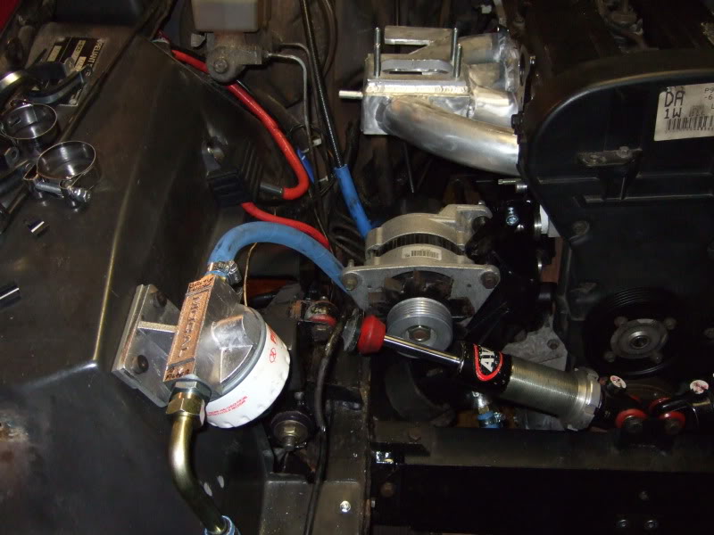
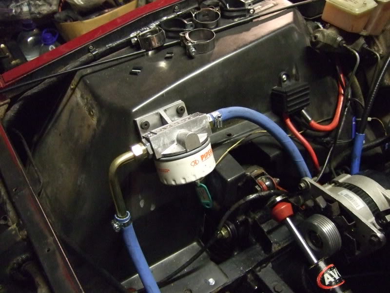
Due to the proximity of the right hand side engine mount to the oil filter housing I’ve had to fit a remote oil filter. I've fitted it to the inner wing, plumbed in the oil lines, re-fitted the engine/alternator mount bracket & secured the top length of coolant pipe with some rubber lined p-clips.
Pics:
And on into 2011:
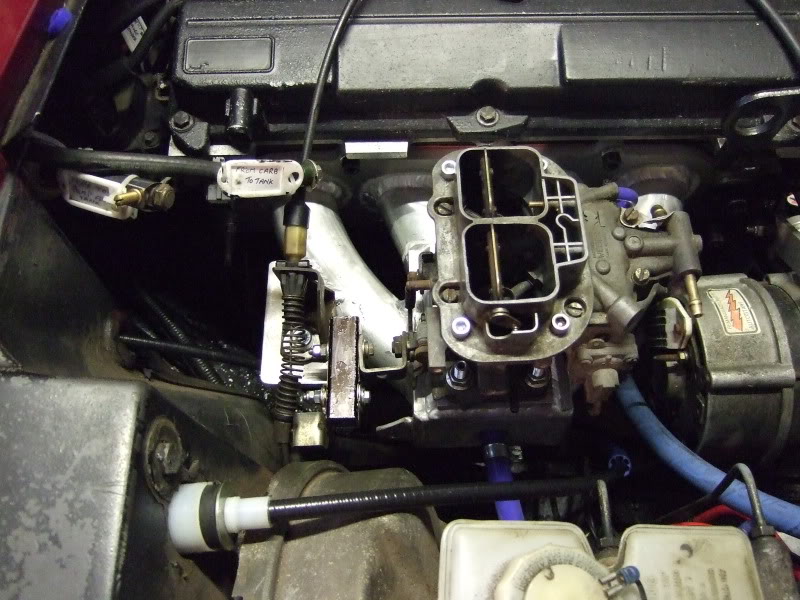
I've managed to adapt the existing throttle cable to fit the DGAV carb. The cable was attached to the old carb (DMTL?) with a ball & socket joint. The cable still had the socket part on the end of it, but the new carb didn’t have the required “ball” on it – I therefore needed to find a way to fit the “ball” bit onto the new carb! Hunting through the bits box resulted in a bit of 20mm steel box section, two small screws & the old carb was kind enough to donate the required “ball” bit.
So with a bit of hacking, drilling & tapping I ended with this: the box section is bolted to the carb, the “ball” bit is bolted to the other end of the box section & the cable then fits to that. It seems to work as it should which is a minor miracle in itself!
For the air filter I’m intending to fit a Weber plenum chamber (designed to fit the DGV/DGAV carbs) onto which I’ll fit some ducting with a remote conical air filter at the end of it. This should keep things nice & low under the bonnet. It looks like the brake master cylinder is the highest part under the bonnet – I’ve not modified this at all - so the bonnet should fit over the new engine without any modifcation.
I’m chuffed that I’ve got three pedals to play around with again
The new carb linkage – looks naff but seems to work well enough
The Weber plenum chamber – not bought yet.
Due to the proximity of the right hand side engine mount to the oil filter housing I’ve had to fit a remote oil filter. I've fitted it to the inner wing, plumbed in the oil lines, re-fitted the engine/alternator mount bracket & secured the top length of coolant pipe with some rubber lined p-clips.
Pics:
And on into 2011:
I've managed to adapt the existing throttle cable to fit the DGAV carb. The cable was attached to the old carb (DMTL?) with a ball & socket joint. The cable still had the socket part on the end of it, but the new carb didn’t have the required “ball” on it – I therefore needed to find a way to fit the “ball” bit onto the new carb! Hunting through the bits box resulted in a bit of 20mm steel box section, two small screws & the old carb was kind enough to donate the required “ball” bit.
So with a bit of hacking, drilling & tapping I ended with this: the box section is bolted to the carb, the “ball” bit is bolted to the other end of the box section & the cable then fits to that. It seems to work as it should which is a minor miracle in itself!
For the air filter I’m intending to fit a Weber plenum chamber (designed to fit the DGV/DGAV carbs) onto which I’ll fit some ducting with a remote conical air filter at the end of it. This should keep things nice & low under the bonnet. It looks like the brake master cylinder is the highest part under the bonnet – I’ve not modified this at all - so the bonnet should fit over the new engine without any modifcation.
I’m chuffed that I’ve got three pedals to play around with again
The new carb linkage – looks naff but seems to work well enough
The Weber plenum chamber – not bought yet.
Last edited by pauluspaolo; 25-04-2012 at 01:54 PM.
25-04-2012, 01:42 PM
#13
15000
Thread Starter
Join Date: Apr 2010
Location: Leeds
Posts: 23
Likes: 0
Received 0 Likes
on
0 Posts
2011
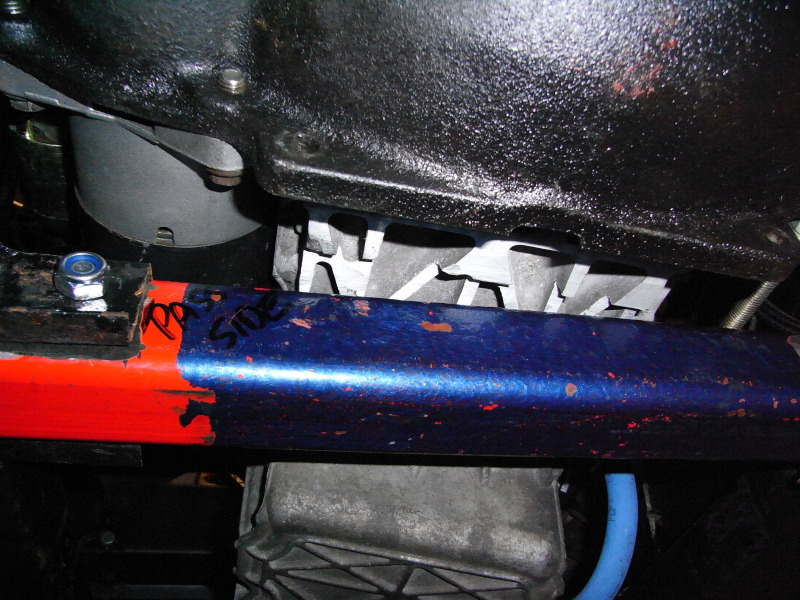
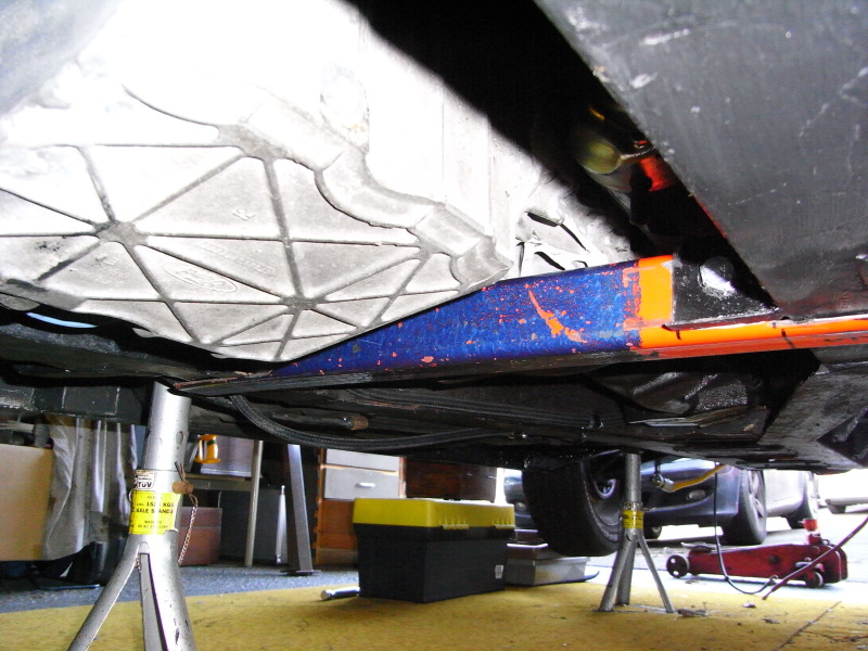
After the success of the throttle cable I decided to tackle running in the new fuel pipes. First thing to do was to try & mock up where I was going to run the new fuel pipe - I was intending to run it along the central tunnel but when it came to actually installing it I decided that it ran too close to the prop shaft. Also, without removing the prop, I couldn't get a drill in to drill the holes for the p-clips. Time for Plan B - which meant running it along the outside of the central tunnel & behind the seat rails (hopefully you'll see what I mean from the pic), passing through the speedometer cable hole into the engine bay. Not sure what the MOT tester will make of it but most of it seems to be tucked up out of the way. I've fitted a fuel pressure regulator/filter in the engine bay & run the fuel pipe from this along the edge of the cam cover to the carb. I've run the fuel return pipe back to the tank along side the other pipe using two p-clips side by side to try & keep the installation neat & tidy.
The photo's aren't very good I'm afraid - & I've yet to take any of the fuel return pipe - but hopefully you can see the run of the fuel pipe under the car - any observations/comments (positive or negative) gratefully received.
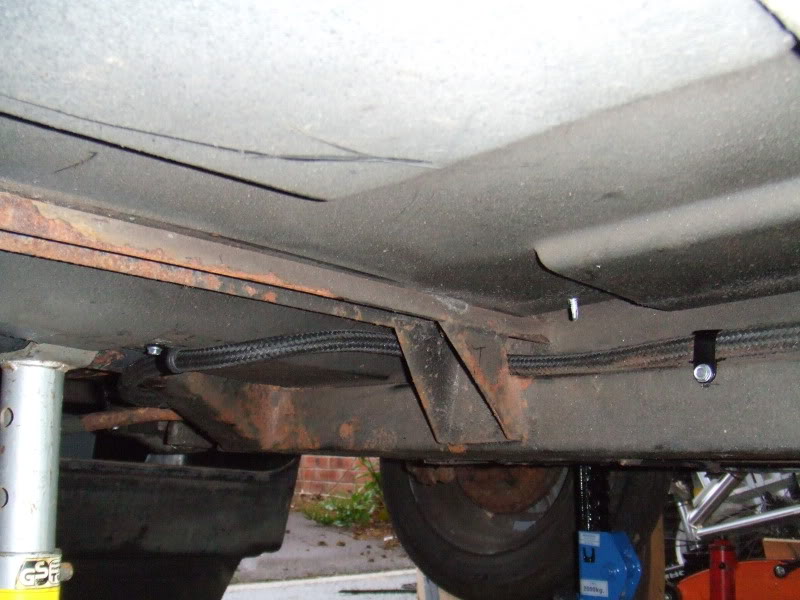
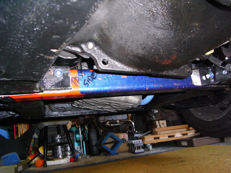
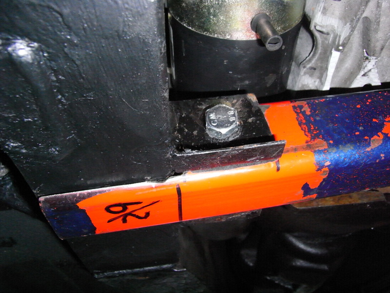
Fuel hose running under the car along central backbone/tunnel & through the gaps behind the seat rails. I've secured it with p-clips along its length, especially at the back of the chassis (not in the photo) where it passes close to the trailing arm as I don't want any moving parts to rub against it!
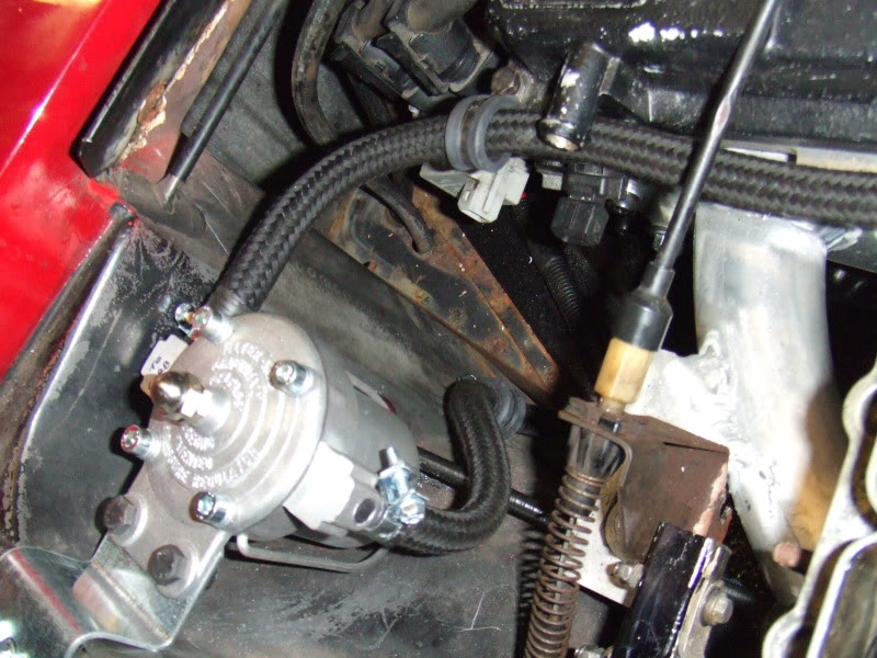
Here we can see where I've mounted the filter king & the new hose attached to it. I've put a dogleg in the filter king mounting plate to lower it. The old fuel pipes can be seen poking through the chassis at the top of the photo - these are now redundant & I'll remove them later.
New fuel hose attached to the carb - I've run it along the edge of the cam cover (using rubber lined stainless steel p-clips) as it looks neat & keeps everything out of the way. The p-clips are a bit too big for the fuel hose but I’m going to wrap a bit of rubber self-amalgamating tape round it to increase the diameter of the hose so the p-clip will hold it.
As I say opinions welcome – I was going to change the route of the new hose while the car's up on stands & the underneath is accessible (up inside the central tunnel would be best/safest - which is where the original piping runs) but I just can't reach it without removing the propshaft - so it's going to stay where it is!
In some of the above pics you can see rust on the seat rail(s) & chassis - much as I'd love to take the body off & check/repair the chassis properly I just don't have the time, or facilities, to attempt this, so I've treated every bit of rust I can find with Jenolite rust remover & Kurust rust inhibitor. I haven't taken any photos of the treated rust (it's not much to look at to be honest) & it all still needs painting - hopefully it'll last a while before I have to do it all again as it's a pretty bloody awful awful job lying on your back with rust remover/inhibitor trickling down your arm!!
I haven't taken any pics but I've also fitted the vaccuum tube that runs from the carb, through the bulkhead, to the megajolt ecu - which I've yet to mount & attempt to wire up.
Next step will be to start stripping the back end down to renew suspension bushes, bearings, trailing arms etc & to treat any rust as & when I find it
After the success of the throttle cable I decided to tackle running in the new fuel pipes. First thing to do was to try & mock up where I was going to run the new fuel pipe - I was intending to run it along the central tunnel but when it came to actually installing it I decided that it ran too close to the prop shaft. Also, without removing the prop, I couldn't get a drill in to drill the holes for the p-clips. Time for Plan B - which meant running it along the outside of the central tunnel & behind the seat rails (hopefully you'll see what I mean from the pic), passing through the speedometer cable hole into the engine bay. Not sure what the MOT tester will make of it but most of it seems to be tucked up out of the way. I've fitted a fuel pressure regulator/filter in the engine bay & run the fuel pipe from this along the edge of the cam cover to the carb. I've run the fuel return pipe back to the tank along side the other pipe using two p-clips side by side to try & keep the installation neat & tidy.
The photo's aren't very good I'm afraid - & I've yet to take any of the fuel return pipe - but hopefully you can see the run of the fuel pipe under the car - any observations/comments (positive or negative) gratefully received.
Fuel hose running under the car along central backbone/tunnel & through the gaps behind the seat rails. I've secured it with p-clips along its length, especially at the back of the chassis (not in the photo) where it passes close to the trailing arm as I don't want any moving parts to rub against it!
Here we can see where I've mounted the filter king & the new hose attached to it. I've put a dogleg in the filter king mounting plate to lower it. The old fuel pipes can be seen poking through the chassis at the top of the photo - these are now redundant & I'll remove them later.
New fuel hose attached to the carb - I've run it along the edge of the cam cover (using rubber lined stainless steel p-clips) as it looks neat & keeps everything out of the way. The p-clips are a bit too big for the fuel hose but I’m going to wrap a bit of rubber self-amalgamating tape round it to increase the diameter of the hose so the p-clip will hold it.
As I say opinions welcome – I was going to change the route of the new hose while the car's up on stands & the underneath is accessible (up inside the central tunnel would be best/safest - which is where the original piping runs) but I just can't reach it without removing the propshaft - so it's going to stay where it is!
In some of the above pics you can see rust on the seat rail(s) & chassis - much as I'd love to take the body off & check/repair the chassis properly I just don't have the time, or facilities, to attempt this, so I've treated every bit of rust I can find with Jenolite rust remover & Kurust rust inhibitor. I haven't taken any photos of the treated rust (it's not much to look at to be honest) & it all still needs painting - hopefully it'll last a while before I have to do it all again as it's a pretty bloody awful awful job lying on your back with rust remover/inhibitor trickling down your arm!!
I haven't taken any pics but I've also fitted the vaccuum tube that runs from the carb, through the bulkhead, to the megajolt ecu - which I've yet to mount & attempt to wire up.
Next step will be to start stripping the back end down to renew suspension bushes, bearings, trailing arms etc & to treat any rust as & when I find it
Last edited by pauluspaolo; 25-04-2012 at 01:54 PM.
25-04-2012, 01:53 PM
#14
15000
Thread Starter
Join Date: Apr 2010
Location: Leeds
Posts: 23
Likes: 0
Received 0 Likes
on
0 Posts
2011
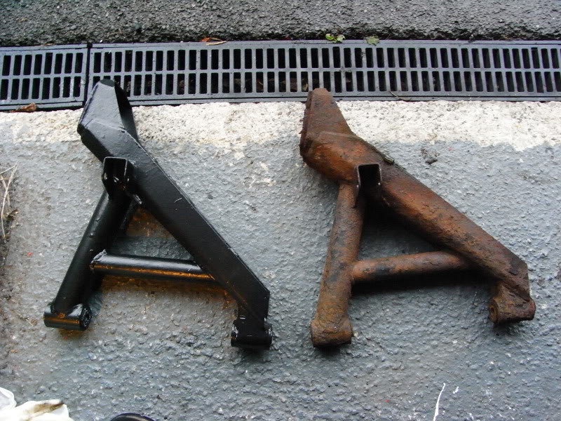
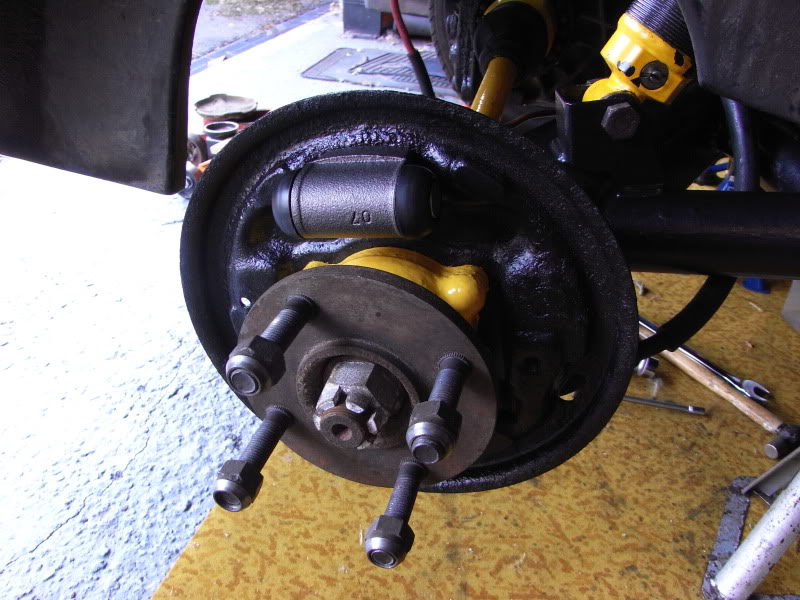
I bought a pair of trailing arms through the ScimWeb forum some time ago & have finally got round to taking the rear end apart in order to fit them. I�ve painted them with 3 layers of paint (which chips easily) so, hopefully, they'll last & look a bit better than the originals. I�ve reconditioned the brakes as well with Goodridge braided hoses, new wheel cylinders (from a Sierra estate so slightly larger bore than the normal ones - should match the vented discs better) & new brake shoes. The drums were ridged & I've had them skimmed rather than buying new ones. I attacked the original backing plates with a wire brush & have managed to re-use these. I thought I�d have to replace the handbrake cable (due to seized adjusters) but have managed to free these off & get them working again. Painted yellow because that's the only colour I had left on the shelf!!
Here are the pics J
New trailing arm compared with the old ones.
New wheel cylinder & repainted backing plate.
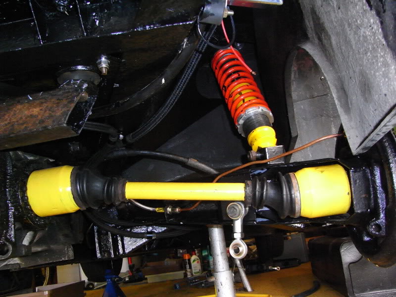
Overall view of backend showing freshly painted drive shaft, new Spax shock & trailing arm. You can also see the new drop link I�ve made up for the anti-roll bar (not re-fitted that yet) from Ebay sourced rose joints - original drop links are no longer available.
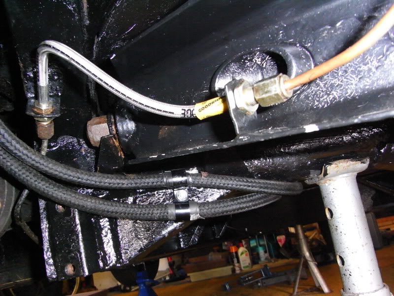
Shot showing the new Goodridge braided brake hose.
J
I bought a pair of trailing arms through the ScimWeb forum some time ago & have finally got round to taking the rear end apart in order to fit them. I�ve painted them with 3 layers of paint (which chips easily
Here are the pics J
New trailing arm compared with the old ones.
New wheel cylinder & repainted backing plate.
Overall view of backend showing freshly painted drive shaft, new Spax shock & trailing arm. You can also see the new drop link I�ve made up for the anti-roll bar (not re-fitted that yet) from Ebay sourced rose joints - original drop links are no longer available.
Shot showing the new Goodridge braided brake hose.
J
Last edited by pauluspaolo; 25-04-2012 at 01:58 PM.
25-04-2012, 01:58 PM
#15
15000
Thread Starter
Join Date: Apr 2010
Location: Leeds
Posts: 23
Likes: 0
Received 0 Likes
on
0 Posts
2012
I finally decided that I wasn�t happy with the new position of the alternator (I�d moved it from passengers side of the engine bay to the drivers side) so I dug out the old alternator/engine mount & decided to try & modify it so that I could use it with the new water pump (the outlet of which is in a different position to that of the old one).
I cut a hole in the mount (lots of drilling & filing) for the water pump outlet but it still didn�t fit, meaning that I had to enlarge the hole considerably until I�d completely removed one side of the original bracket/mount. The bracket now fitted over the pump outlet but was considerably weakened so I had to be put some/all of the strength back into it. Not having access to a welder meant that a - hopefully - superior bodge was required! Cue one strip of extremely hard steel, some spacers & some M8 bolts. The result isn't the prettiest bit of bodgery ever seen but it seems pretty strong & will do for now (I plan to get it welded up later on). It also it means that I�ve finally found a use for the Landrover alternator adjusting strap I bought ages ago (which is much longer than the standard SS1 item). Apologies but the pics aren�t the best & I�ll try to take some better ones when it�s off the car.
The drive belt fits fine & was originally intended for a 2 litre Lancia Thema, amongst others, & is 1100mm long with 4 ribs.
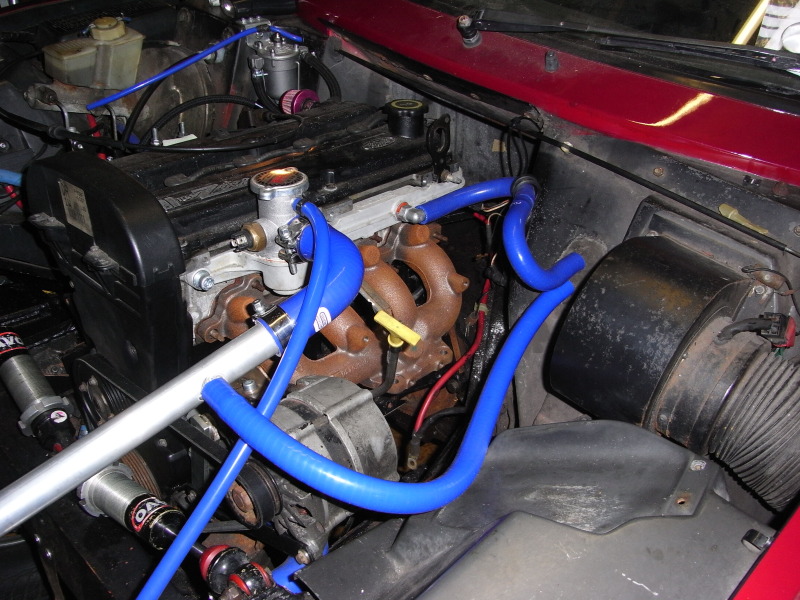
The picture(s) also show the exhaust manifold I�m probably going to use (at least initially) � it�s a bog standard Mondeo jobbie so probably won�t flow that well but it�ll do to get the car up & running with. I suspect that due to the position of the alternator, water rail & starter motor I�ll either end up lumbered with it or I�ll end up having to get a one off manifold built up on the car at a later date.
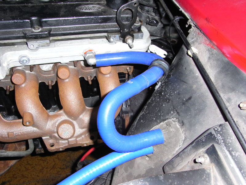
Solving one problem always seems to lead to others & I�ll have to re-route one of the heater hoses as it runs too close to the manifold. I've been wanting to replace them with silicon hoses for a while now so it�s not a biggie really. Also due to the new (old?) position of the alternator I�ve had to move the dipstick tube & have secured it to one of the thermostat housing bolts.

I finally decided that I wasn�t happy with the new position of the alternator (I�d moved it from passengers side of the engine bay to the drivers side) so I dug out the old alternator/engine mount & decided to try & modify it so that I could use it with the new water pump (the outlet of which is in a different position to that of the old one).
I cut a hole in the mount (lots of drilling & filing) for the water pump outlet but it still didn�t fit, meaning that I had to enlarge the hole considerably until I�d completely removed one side of the original bracket/mount. The bracket now fitted over the pump outlet but was considerably weakened so I had to be put some/all of the strength back into it. Not having access to a welder meant that a - hopefully - superior bodge was required! Cue one strip of extremely hard steel, some spacers & some M8 bolts. The result isn't the prettiest bit of bodgery ever seen but it seems pretty strong & will do for now (I plan to get it welded up later on). It also it means that I�ve finally found a use for the Landrover alternator adjusting strap I bought ages ago (which is much longer than the standard SS1 item). Apologies but the pics aren�t the best & I�ll try to take some better ones when it�s off the car.
The drive belt fits fine & was originally intended for a 2 litre Lancia Thema, amongst others, & is 1100mm long with 4 ribs.
The picture(s) also show the exhaust manifold I�m probably going to use (at least initially) � it�s a bog standard Mondeo jobbie so probably won�t flow that well but it�ll do to get the car up & running with. I suspect that due to the position of the alternator, water rail & starter motor I�ll either end up lumbered with it or I�ll end up having to get a one off manifold built up on the car at a later date.
Solving one problem always seems to lead to others & I�ll have to re-route one of the heater hoses as it runs too close to the manifold. I've been wanting to replace them with silicon hoses for a while now so it�s not a biggie really. Also due to the new (old?) position of the alternator I�ve had to move the dipstick tube & have secured it to one of the thermostat housing bolts.
Last edited by pauluspaolo; 25-04-2012 at 01:59 PM.
25-04-2012, 02:02 PM
#16
15000
Thread Starter
Join Date: Apr 2010
Location: Leeds
Posts: 23
Likes: 0
Received 0 Likes
on
0 Posts
2012
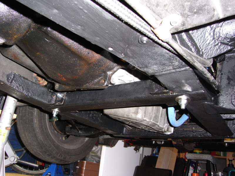
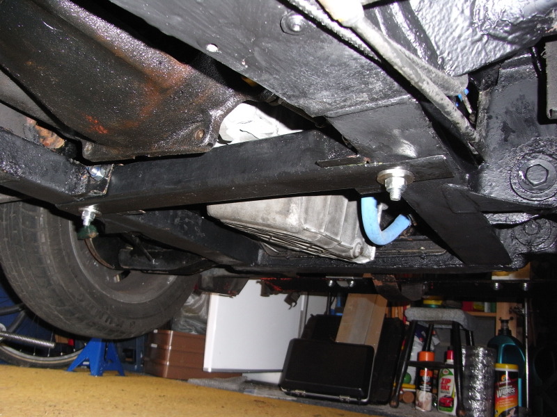
Thought I’d get the engine bay rear cross-member back in. Normally it’s a fairly weedy looking - though probably pretty strong in fact - bit of top hat section of steel. I had to remove it in order to fit the Zetec sump. I’d left stubs either side of the engine bay thinking that I’d either refit the original, or make a removable one, at some stage. However it soon became clear that because the sump is so close to it that a removable cross-member would probably make things easier – especially if I ever need to drop the sump or remove the engine at a later date.
I’ve used a length of square section steel (part of an old engine stand I was given) which, with a bit of tickling with the angle-grinder, fitted inside the stubs of the original cross-member. I’ve cut it to fit between the main chassis members but left overhangs each side. I’ve drilled through the stubs, & the square section, & put M10 bolts through to secure the square section to the stubs. Since the photos were taken I’ve drilled up through each of the overhangs, & chassis rails, & put another M10 bolt through. So it’s secured by both horizontal & vertical M0 bolts. I’m not sure I’ve described that very well but hopefully you can see what I mean from the photos.
I’ve no idea if it’s as strong as, or maybe even stronger than, the original - & some of the drilling isn’t brilliant (space was tight with the underneath of the car just above your nose which made drilling, even with a right angle drill, anything but easy) – but I feel happier with it there. Of course it all needs to come out again so that I can paint it!
Last edited by pauluspaolo; 25-04-2012 at 02:05 PM.
25-04-2012, 02:11 PM
#17
15000
Thread Starter
Join Date: Apr 2010
Location: Leeds
Posts: 23
Likes: 0
Received 0 Likes
on
0 Posts
March 2012
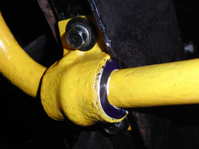
No theatre duties (my other very time consuming hobby!) until June means that I can finally get a few consecutive evenings in working on the car – unfortunately painting a freshly stripped anti-roll bar isn’t very exciting & you can only give it one coat of paint at a time so 3 coats of paint requires 3 evenings ….. & taking photos of paint drying is about as exciting as watching it dry! Anyway said painting was finally completed & I refitted the front anti-roll bar with the help of my “Westfield in bits” owning friend Matt (thanks Matt J ). I’d bought new polyurethane bushes for both the front & rear ARB’s sometime ago (read: years ago) so after remembering where they'd been stashed, I dug them out & fitted them at the same time. Didn’t take long in the grand scheme of things & the jobs a good ‘un.
Front ARB drop links + poly bushes:
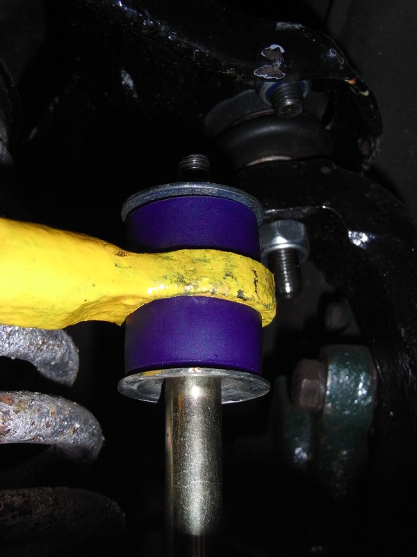
Front ARB chassis mount & poly bush:
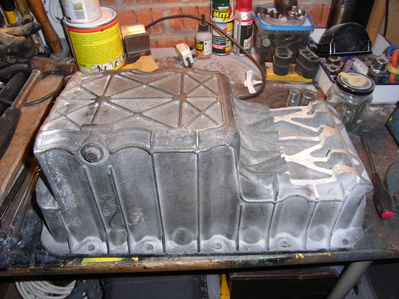
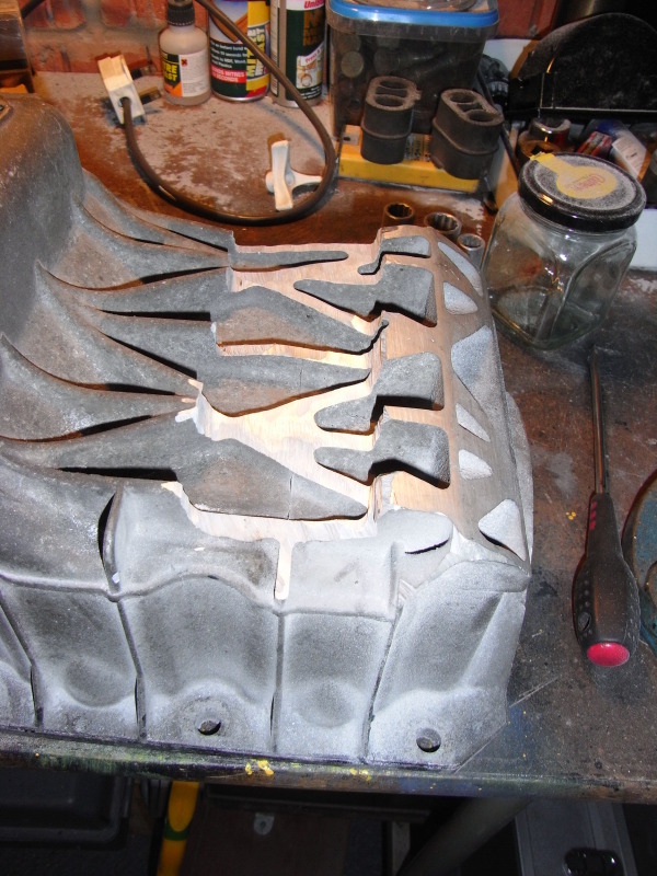
I also attacked the sump with my angle grinder …... AGAIN!! …… as I wasn't happy about it being so close to the new crossmember (see previous post). This is the result & the channel should, hopefully, give more clearance. Note all the alloy dust in the background – I had a big clean/tidy up just after this photo was taken so I have a nice clean tidy garage to clutter up again.
No theatre duties (my other very time consuming hobby!) until June means that I can finally get a few consecutive evenings in working on the car – unfortunately painting a freshly stripped anti-roll bar isn’t very exciting & you can only give it one coat of paint at a time so 3 coats of paint requires 3 evenings ….. & taking photos of paint drying is about as exciting as watching it dry! Anyway said painting was finally completed & I refitted the front anti-roll bar with the help of my “Westfield in bits” owning friend Matt (thanks Matt J ). I’d bought new polyurethane bushes for both the front & rear ARB’s sometime ago (read: years ago) so after remembering where they'd been stashed, I dug them out & fitted them at the same time. Didn’t take long in the grand scheme of things & the jobs a good ‘un.
Front ARB drop links + poly bushes:
Front ARB chassis mount & poly bush:
I also attacked the sump with my angle grinder …... AGAIN!! …… as I wasn't happy about it being so close to the new crossmember (see previous post). This is the result & the channel should, hopefully, give more clearance. Note all the alloy dust in the background – I had a big clean/tidy up just after this photo was taken so I have a nice clean tidy garage to clutter up again.
Last edited by pauluspaolo; 25-04-2012 at 02:14 PM.
 25-04-2012, 02:34 PM
#19
15000
Thread Starter
Join Date: Apr 2010
Location: Leeds
Posts: 23
Likes: 0
Received 0 Likes
on
0 Posts
April 2012.
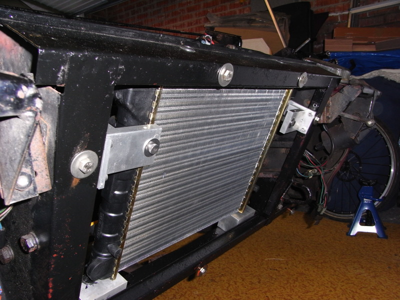
I fitted a new radiator to the SS1 last month. It’s actually for a 1 litre Polo (I think) but these radiators are used in Zetec engined kit cars & my friend, who’s rebuilding a Westfield with a stage 3 tuned crossflow engine, is using one of these radiators. It’s slightly smaller than the standard SS1 radiator so required a couple of raising blocks, new mounts & some re-routing of the coolant hoses.
I’ve also used a Polo cooling fan which fits directly onto the old Reliant fan mount with no modifications at all – bar some washers/spacers to keep it away from the anti-roll bar. This must make it one of the cheapest/easiest upgrades available for the SS1 & the original fan looks pathetic next to it.
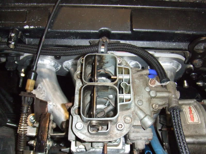
I was going to use a second-hand DGAV carb but whilst renewing the gaskets, needle valves etc I found that it had some parts missing Sod it (or words to that effect!) I thought & decided to dip into the piggy bank & order a new DGV carb (no fuel return or auto-choke). Could've have done wthout the extra expense but at least I know the new carb will be set up properly (it’s being jetted for a 2 litre Pinto). The old black rubber heater hoses have gone & been replaced with blue silicon ones; unfortunately I’ve ordered the wrong sized hose clips so I’ll have to re-order & fit these later on.
As well as all the above I’ve refitted the sump, starter motor & cross-member.
Next step is installing the Megajolt – not sure where to start to be honest – after that the exhaust manifold/system will be the next big headache as the only manifold I’ve found that fits is the standard Mondeo cast iron one – not exactly free-flowing – and there’s damn all room/clearance for a down pipe So I think it’ll have to be a bodge job until I can afford something better – but that’s a bridge I’ll cross when I come to it.
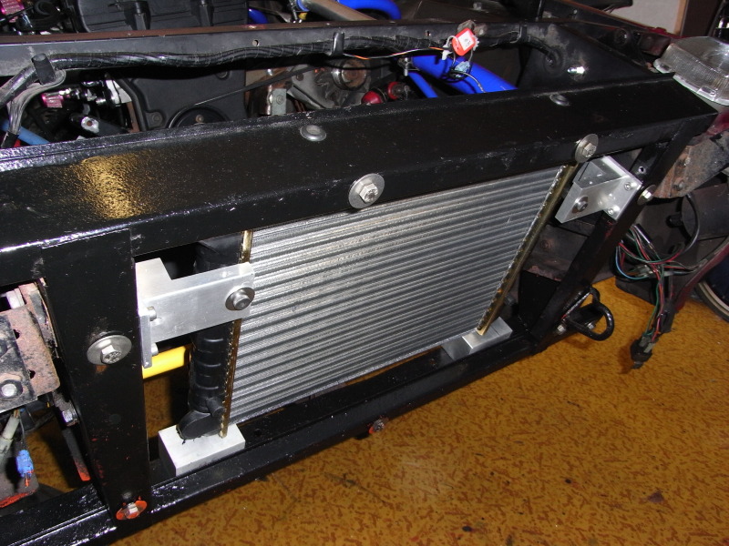
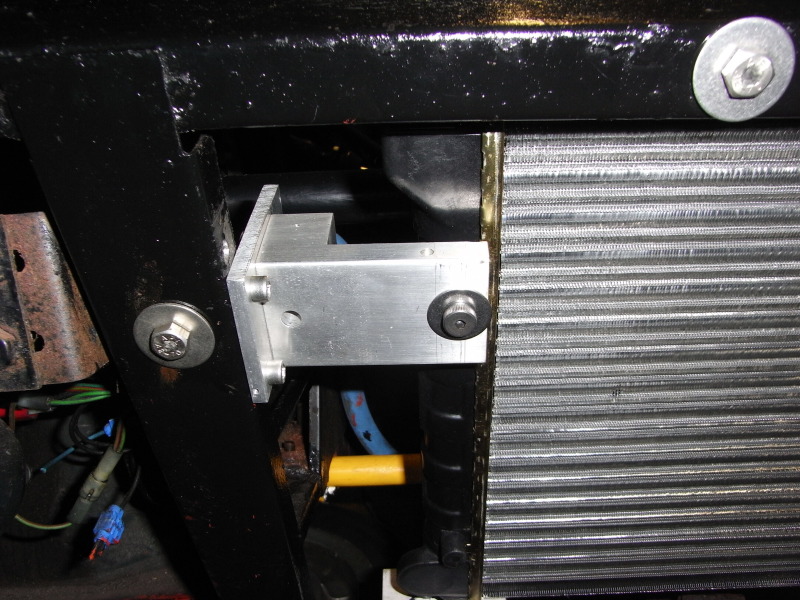
Finally a couple of photos of the new cross member painted up & in position.
I fitted a new radiator to the SS1 last month. It’s actually for a 1 litre Polo (I think) but these radiators are used in Zetec engined kit cars & my friend, who’s rebuilding a Westfield with a stage 3 tuned crossflow engine, is using one of these radiators. It’s slightly smaller than the standard SS1 radiator so required a couple of raising blocks, new mounts & some re-routing of the coolant hoses.
I’ve also used a Polo cooling fan which fits directly onto the old Reliant fan mount with no modifications at all – bar some washers/spacers to keep it away from the anti-roll bar. This must make it one of the cheapest/easiest upgrades available for the SS1 & the original fan looks pathetic next to it.
I was going to use a second-hand DGAV carb but whilst renewing the gaskets, needle valves etc I found that it had some parts missing
As well as all the above I’ve refitted the sump, starter motor & cross-member.
Next step is installing the Megajolt – not sure where to start to be honest – after that the exhaust manifold/system will be the next big headache as the only manifold I’ve found that fits is the standard Mondeo cast iron one – not exactly free-flowing – and there’s damn all room/clearance for a down pipe So I think it’ll have to be a bodge job until I can afford something better – but that’s a bridge I’ll cross when I come to it.
Finally a couple of photos of the new cross member painted up & in position.
25-04-2012, 03:28 PM
#20
15000
Thread Starter
Join Date: Apr 2010
Location: Leeds
Posts: 23
Likes: 0
Received 0 Likes
on
0 Posts
On Ebay last week I won a CVH free(ish) flow exhaust manifold, which came off another SS1. My idea being to fit this manifold to the Zetec using an adaptor plate(also from Ebay).
I started getting the engine ready for the adapter & new manifold which meant removing the coolant pipes/hoses, the alternator, alternator/engine mount & the Mondeo exhaust manifold that was already fitted & I was intending to use. The adaptor is fitted to the Zetec head using allen headed bolts in the holes the original exhaust studs were in � so the studs obviously had to come out. These handily have a Torx head on them meaning that I managed to get 8 of the 9 studs out without too much bother. The last one refused to loosen though & was too close to the water rail to use a stud remover. The last thing I wanted to do was shear it off in the head so the water rail had to come off as well!
After all the above was accomplished I fitted the adaptor & CVH exhaust manifold and refitted the alternator/engine mount, alternator, coolant pipes etc. All went reasonably smoothly & the manifold fits fine so I should be able to use the exhaust that came with the car - at least initially until I can afford something better.. As the picture(s) show the adaptor plate overlaps the exhaust port slightly � which I�m not too happy about � so I've chamfered the edges of it slightly to allow the exhaust gasses out a bit more easily.
So there you have it � that�s the engine installation just about finished I still need to sort out the air filter but I know what I'm going to use so that's not too big a problem. The next major job on the horizon is the wiring (Megajolt ecu/EDIS installation, cooling fan, fuel pump etc).
That's where I'm up to really & what I'm thinking of doing this weekend is hooking up the battery & trying the starter motor - it'd be nice to know that it engages with the flywheel I'm using & turns the engine over! Wish me luck
Couple of photos showing the adaptor plate fitted - note overlap on ports.
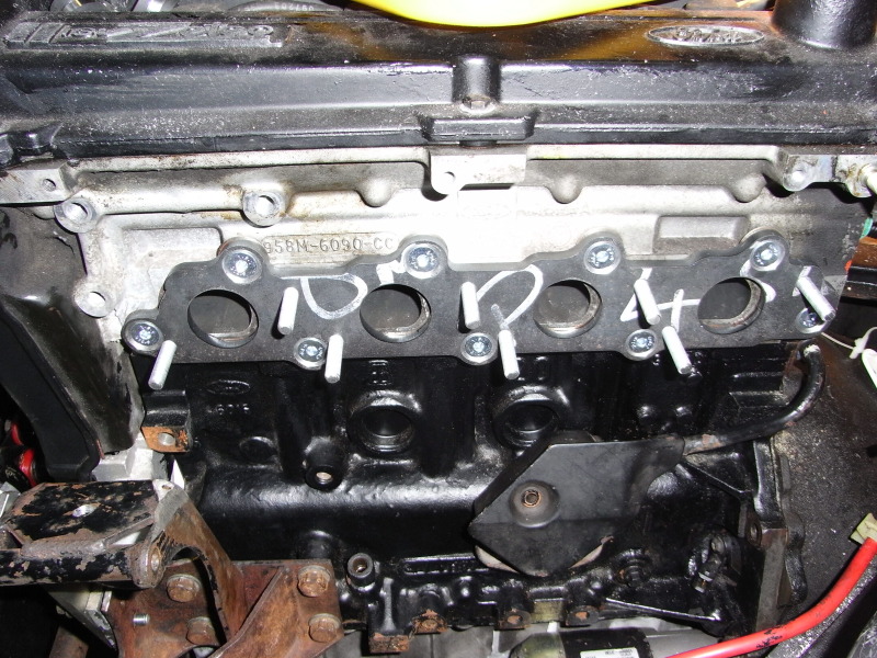
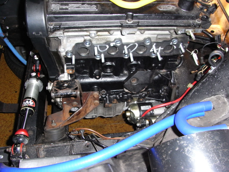
Everything back together.
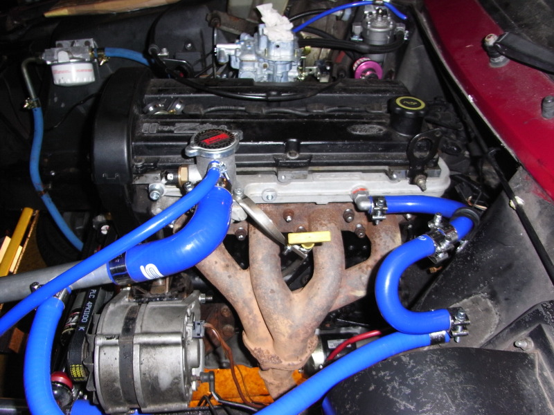
Exhaust manifold exit under the car.
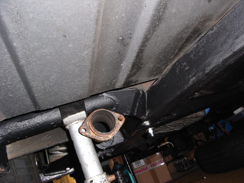
Opinions welcome as always J
I started getting the engine ready for the adapter & new manifold which meant removing the coolant pipes/hoses, the alternator, alternator/engine mount & the Mondeo exhaust manifold that was already fitted & I was intending to use. The adaptor is fitted to the Zetec head using allen headed bolts in the holes the original exhaust studs were in � so the studs obviously had to come out. These handily have a Torx head on them meaning that I managed to get 8 of the 9 studs out without too much bother. The last one refused to loosen though & was too close to the water rail to use a stud remover. The last thing I wanted to do was shear it off in the head so the water rail had to come off as well!
After all the above was accomplished I fitted the adaptor & CVH exhaust manifold and refitted the alternator/engine mount, alternator, coolant pipes etc. All went reasonably smoothly & the manifold fits fine so I should be able to use the exhaust that came with the car - at least initially until I can afford something better.. As the picture(s) show the adaptor plate overlaps the exhaust port slightly � which I�m not too happy about � so I've chamfered the edges of it slightly to allow the exhaust gasses out a bit more easily.
So there you have it � that�s the engine installation just about finished I still need to sort out the air filter but I know what I'm going to use so that's not too big a problem. The next major job on the horizon is the wiring (Megajolt ecu/EDIS installation, cooling fan, fuel pump etc).
That's where I'm up to really & what I'm thinking of doing this weekend is hooking up the battery & trying the starter motor - it'd be nice to know that it engages with the flywheel I'm using & turns the engine over! Wish me luck
Couple of photos showing the adaptor plate fitted - note overlap on ports.
Everything back together.
Exhaust manifold exit under the car.
Opinions welcome as always J
Last edited by pauluspaolo; 25-04-2012 at 03:30 PM.
25-04-2012, 06:01 PM
#22
15000
Thread Starter
Join Date: Apr 2010
Location: Leeds
Posts: 23
Likes: 0
Received 0 Likes
on
0 Posts
Thanks again for the feedback - I'll try & remember to post any future updates
Last edited by pauluspaolo; 25-04-2012 at 06:03 PM.
13-07-2012, 01:47 PM
#24
15000
Thread Starter
Join Date: Apr 2010
Location: Leeds
Posts: 23
Likes: 0
Received 0 Likes
on
0 Posts
Well here's a short video of the engine running on EDIS only & minus any sort of exhaust (bar a loosely fitted manifold) - the voiceover at the beginning belongs to my Westfield owning friend Matt - he's an amateur thespian in case you hadn't guessed
The car took a lot of getting going with some fairly spectacular fireworks/mushroom clouds from the carb! It eventually fired up (sort of) but wouldn't idle & I'm not convinced it's firing on all 4 cylinders - quite hard to tell though without an exhaust (which will also affect how the car runs) - each plug was getting a spark. Having read a bit about DGV/DGAV carbs I'm going to check the basic settings when I get home tonight - though the carb was new so I sort of assumed that it'd be set to the basics already
On a more positive note the clutch works as I tried reversing the car despite there being no drivers seat, no brakes & with the engine running as rough as a bears bum
Video shot in May 2012.
http://s9.photobucket.com/albums/a88/pauluspaolo/Videos%20of%20the%20SS1/?action=view¤t=VID00001.mp4
Since the above video I’ve bought, & fitted, a complete stainless steel exhaust system (from another SS1), tightened up the inlet manifold (which has stopped the spitting back/mushroom clouds), tweaked the idle/mixture settings on carb & loaded a map onto the Megajolt ….. the car’s now idling/running much better than it was in the previous video. The map loaded is for a standard cross flow, all the Zetec maps I could find were for engines running twin 40/45’s. If anyone has an ignition map for a Zetec running a single Weber DGV carb then I’d very much like to hear from them. Also does knows what jets to use in a DGV carb that’s attached to a 2 litre Zetec?? The carb was new, I’ve not opened it up, so I’m not sure what the main jet sizes are but the idle jets are: primary choke – 165, secondary choke – 160. I asked for it to be jetted for a 2 litre Pinto (Cortina/Capri etc).
As I say the car’s running much better but I thought I may go up/down a couple of idle jet sizes i.e. primary choke up to 170 or down to 160 & secondary choke up to 165 or down to 155. The jets are only a couple of quid each so cheap enough to buy & experiment with but if I change the idle jet sizes will I need to change the emulsion tubes & the main jet sizes as well??
As you can probably tell I’ve no idea what I’m doing so, once again, any advice would be much appreciated L!!
Anyway here’s another video of it running much better earlier this month J
http://s9.photobucket.com/albums/a88/pauluspaolo/Videos%20of%20the%20SS1/?action=view¤t=Zetecrun2EDIS.mp4
J
Last edited by pauluspaolo; 13-07-2012 at 01:50 PM.
29-05-2013, 09:52 AM
#25
15000
Thread Starter
Join Date: Apr 2010
Location: Leeds
Posts: 23
Likes: 0
Received 0 Likes
on
0 Posts
Hi all there's been lots of progress made since the above update & the car is, to all intents & purposes, finished J
I booked last Thursday & Friday off work. Thursday was spent finally putting the car back together, with the MOT booked first thing on Friday. This would give me the rest of Friday & the long bank holiday weekend to rectify any faults the MOT threw up.
Well I�m happy to say that the long weekend wasn�t really needed as the car passed first time without any advisories JJ So the weekend was actually spent gardening & doing a few minor jobs on the car � like refitting the headlight surrounds (one of these still needs painting so isn�t fitted yet) & tidying up the interior.
I tried taxing the car straight after the MOT but the lady at the PO wouldn�t accept my insurance certificate so I went home & did it online meaning that I can�t drive the car until the tax disc arrives. The tax disc in the car now ran out in 2009 so I don�t want to risk driving the car until the new one�s arrived. All a bit frustrating really but it�s taken me 4 years to get this far so waiting another week or so isn�t a biggie really.
Here are some photos � in no particular order:
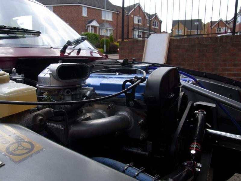
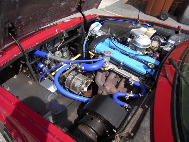
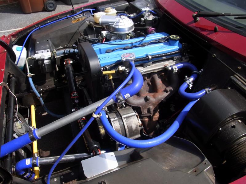
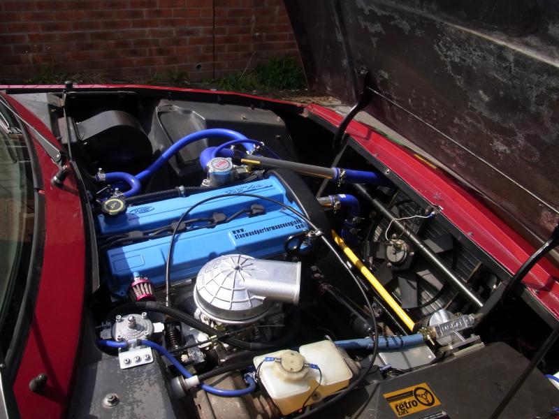
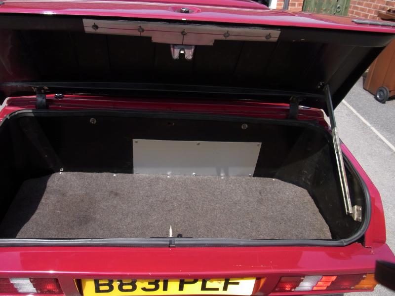
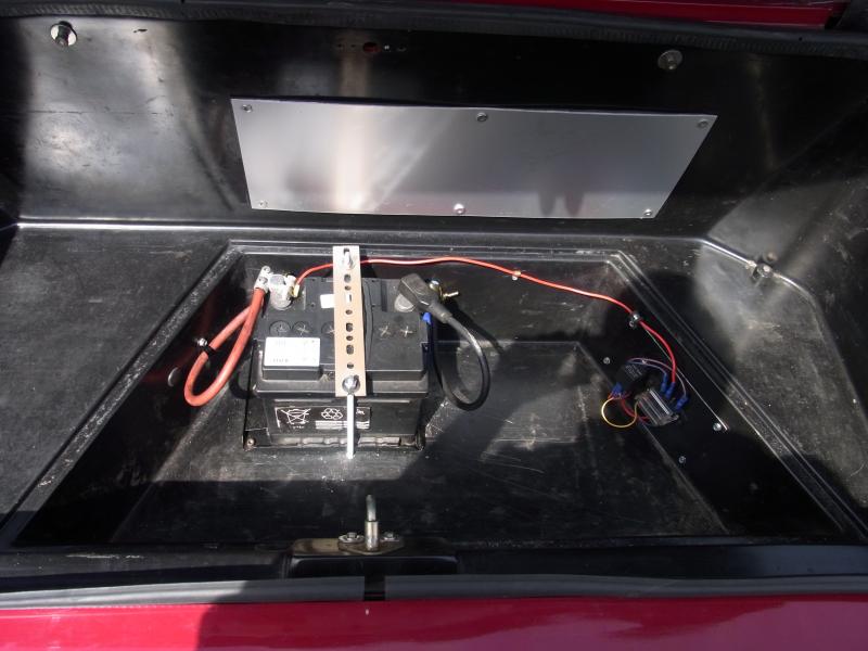
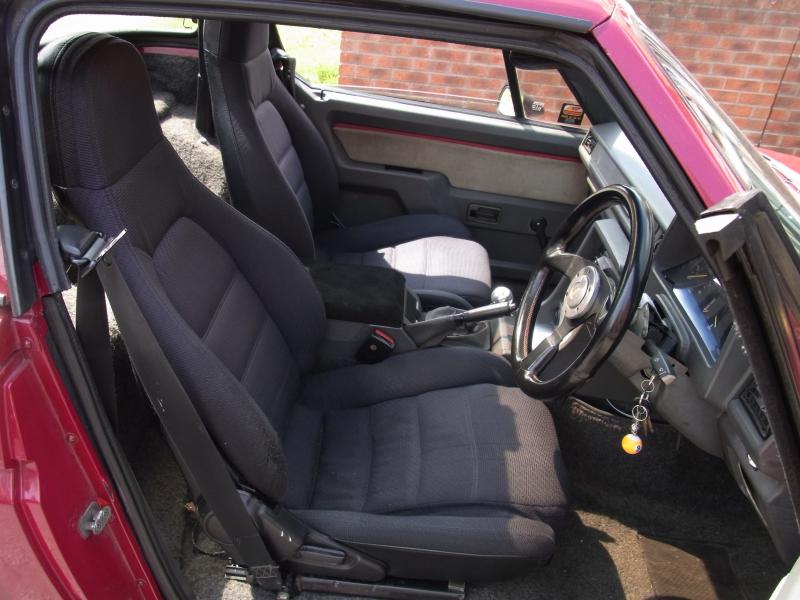
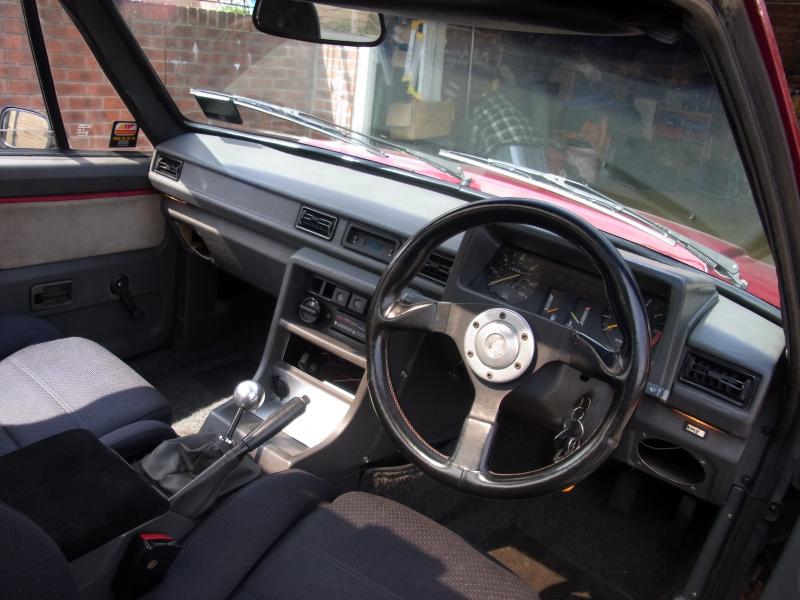
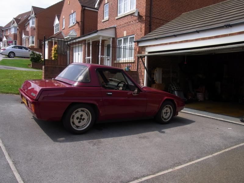
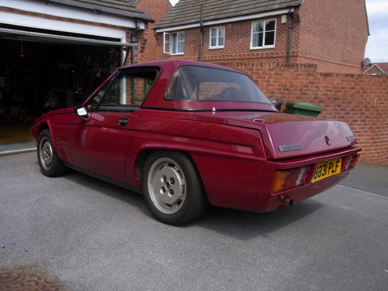
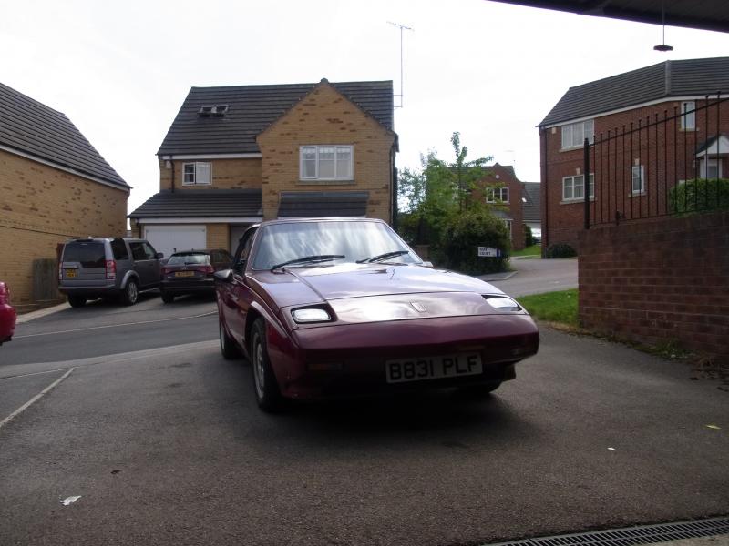
J
I booked last Thursday & Friday off work. Thursday was spent finally putting the car back together, with the MOT booked first thing on Friday. This would give me the rest of Friday & the long bank holiday weekend to rectify any faults the MOT threw up.
Well I�m happy to say that the long weekend wasn�t really needed as the car passed first time without any advisories JJ So the weekend was actually spent gardening & doing a few minor jobs on the car � like refitting the headlight surrounds (one of these still needs painting so isn�t fitted yet) & tidying up the interior.
I tried taxing the car straight after the MOT but the lady at the PO wouldn�t accept my insurance certificate so I went home & did it online meaning that I can�t drive the car until the tax disc arrives. The tax disc in the car now ran out in 2009 so I don�t want to risk driving the car until the new one�s arrived. All a bit frustrating really but it�s taken me 4 years to get this far so waiting another week or so isn�t a biggie really.
Here are some photos � in no particular order:


J
 02-08-2013, 10:38 AM
#28
15000
Thread Starter
Join Date: Apr 2010
Location: Leeds
Posts: 23
Likes: 0
Received 0 Likes
on
0 Posts
Tail lights are Capri units but fitted upside down - the doors aren't reskinned Fiesta; you're thinking of Ginetta, I think, who used this method on some of their cars. They're glassfibre & Reliant/Michelotti designed - the car was Michelotti's last design to reach production (4 years after his death).
I'm happy to say that the car drives a lot better than it looks! I like the looks but can appreciate that they're not to everyone's taste! Most people's immediate reaction is that the car's ugly but I think it's well proportioned & has definite good angles (the rear 3/4 & side views are nice) & bad angles (the front view isn't the best) - it's not helped by the fussy details (the over arch flares, multitude of panel gaps etc).
I was out in it last night (just about the first time I've driven it in the dark) & bar a dodgy temperature gauge there weren't any problems at all. I've recently had the car rolling road tuned so the car runs/starts much better now. The rolling road operator (Dennis Vessey near Brigg) gave it a power run & got 108bhp (87 at wheels) at around 5,000rpm. This is a fair bit lower than I was expecting but given the restrictive exhaust manifold, the carb/air filter I've fitted & the fact I wanted it to be useable on the road, he thought that was about as good as he could get it. I have plans to replace the exhaust manifold (no money at the mo) so that may well improve things.
Despite the relatively low power the car only weights 900(ish)kg's & goes very well ...... a bit too well as it happens because I've been done for speeding - my first points in years
My own stupid fault though & I still like the car
Last edited by pauluspaolo; 02-08-2013 at 11:03 AM.


Thread
Thread Starter
Forum
Replies
Last Post
Tony W
Technical help Q & A
0
09-09-2015 12:08 PM