custom transmission fabrication.
 21-04-2014, 10:22 PM
#1
Im currently looking into a mid engined 4 wheel drive project.
For simplicity it will be based around cosworth 4x4 running gear with the gearbox mounted in the usual position. The engine then drives the gearbox through a prop. once power enters the box, all is as per normal 4x4 cosworth to each diff etc.
This presents a couple of obvious technical problems. easiest it dealing with clutch, you have it off the engine as normal. second is drive coming forward to the side of the gearbox needs to make its way into the gearbox input shaft. Some sort of chain or cogged transfer arrangement will sort that.
The biggest problem is reversing the engine rotation.
Now on the outset you hear of people coming up with stupid ideas like turning diffs,upside down gearboxs etc all of which are easily dismissed as simply not working or highly technically flawed.
In the offroad world its quite common to use a reversing transfer box post gearbox to sort it all out. However that only works if you have the gearbox on the engine.
So what im thinking from a more simplistic way is to use a cut down mt75. It solves the bellhousing clutch issue.
Now as i understand it, drive enters the box then through continously meshed gears goes from the input shaft to counter/layshaft then back to the driven shaft and out the back of the box.
Of interest is the continuosly meshed gears. They are taking all the torque all the time so are fairly strong, and are available straight cut from an upgrade point of view.
What i would do is fuck off the entire driven shaft and all gears bar the continually meshed gears.
You can then intheory shorten the casing like 90%. The countershaft then is machined to take a drive output for the prop.
Obviously it needs custom backplate to hold the bearings and it may well work out easier to have a driven shaft fabricated to suit rather than mod original.
The end game would be a mt75 bellhousing with a tiny rear case with a propshaft mount coming out a bit lower than expected. (good for layout of props).
I can't see any reason technically why it wouldnt work.
fabrication is the hard part.
Is the precision machining the sort of thing that a typical CNC/ general precision engineering firm could do comfortably?? or would it need to be a transmission specialist??
Anybodies views on how to build it??
 21-04-2014, 10:48 PM
#2
Ive no idea what you're trying to describe ?
And why would you need the engine to turn the opposite way ?
A Cossie engine with MT75 mounted in the usual way, and then you say the box needs driven off a propshaft ?
So clearly not mounted in any usual way ?
DJM Motorsport could build whatever you need. Probably 5 figure sum though.
But you'd need to be more descriptive or clear about exactly what you need.
Last edited by stevieturbo; 21-04-2014 at 10:49 PM.
21-04-2014, 11:31 PM
#3
you dont get it clearly 
if the engine is pointing backwards, same as an rs200, then unless you reverse the direction of the engine output (with a gear or similar) then when the propshaft drive arrives forward to the gearbox (mounted same way as in a cossie) then it will be rotating the wrong way and the gearbox will run backwards.
Hence why engine rotation direction needs to be reversed in a transfer box (not the actual engine itself).
So as above im trying to use a cut down gearbox to do that direction change, as the layshaft rotates in a different direction to the engine which is what i need......

 22-04-2014, 06:48 AM
#6
Advanced PassionFord User
I've seen 2 rs200 replica kit cars and that ran a cossie 4x4 in the back . We had another turn up at our meet a few years back . Again cossie powered .
Have a look around as they have the engine facing the correct way
Have a look around as they have the engine facing the correct way
22-04-2014, 08:29 AM
#7
You never mentioned a rear facing engine.
You could take the engine mate it to a typical FWD transmission, and then you have two shafts going out each way. ie one to front, one to rear
Then just source suitable diff's for their direction of rotation.
If you needed reverse rotation, maybe one of the Honda boxes that normally run an anticlockwise engine might work better
That's probably the cheapest and most compact way of achieving it.
Trending Topics
22-04-2014, 09:55 AM
#8
Got all the carbon, got the resins, done the test panels I want etc. just need workshop space then i can start to jig things and get moulding.
You never mentioned a rear facing engine.
You could take the engine mate it to a typical FWD transmission, and then you have two shafts going out each way. ie one to front, one to rear
Then just source suitable diff's for their direction of rotation.
If you needed reverse rotation, maybe one of the Honda boxes that normally run an anticlockwise engine might work better
That's probably the cheapest and most compact way of achieving it.
You could take the engine mate it to a typical FWD transmission, and then you have two shafts going out each way. ie one to front, one to rear
Then just source suitable diff's for their direction of rotation.
If you needed reverse rotation, maybe one of the Honda boxes that normally run an anticlockwise engine might work better
That's probably the cheapest and most compact way of achieving it.
i shall get drawing in ms paint....
22-04-2014, 09:56 AM
#9
Have a look at the Quaife R4GTS. the original one used a cosworth YB and running gear mounted backwards to make it rear engined.
i cant find a lot with a quick google other than it now uses a V8 engine, but i dont have time at the mo to keep looking.

i cant find a lot with a quick google other than it now uses a V8 engine, but i dont have time at the mo to keep looking.
22-04-2014, 10:08 AM
#10
Or bolt a Cossie engine to an Audi R8 or Porsche 911 drivetrain LOL
Or find some RS200 running gear, metro 6R4 ?
22-04-2014, 10:31 AM
#11
The porsche stuff youd have to turn it upside down to work. Fine on a midmounted RWD car as you just use the G50 box which is designed to run "upside down" in mid mounted applications and was adapted for road cars. However its 4wd sibling box isnt so designed for upside down running.
The way im invisiging it should be massively cheaper as you are only fabricating 2 parts, a simple cross transfer box to move the drive sideways from the rear to front prop, into the gearbox, and the reverse rotation housing. Got to be much much cheaper than buying a quaife rs200 drivetrain at �25k plus
interesting concept, worth some digging but i suspect with quaife costs, id be just as better off buying a complete RS200 transmission package off them!!
22-04-2014, 10:44 AM
#12
I dont see how you'll ever find more compact than a normal FWD transmission, whether the engine faces forwards or rearwards.
And that approach will be by far the cheapest.
Any transaxle, RWD or whatever will be far longer than a FWD box.
And that approach will be by far the cheapest.
Any transaxle, RWD or whatever will be far longer than a FWD box.
 22-04-2014, 12:26 PM
#14
For the most part it shouldnt be difficult.
Just take a normal input shaft and use it as the top green bit.
Then modify the matching laygear for the lower. Then build a small case to house them.
You could probably make a lot from cutting/welding existing components
Just take a normal input shaft and use it as the top green bit.
Then modify the matching laygear for the lower. Then build a small case to house them.
You could probably make a lot from cutting/welding existing components
22-04-2014, 01:19 PM
#15
Thats why i want to do it that way as it should be simple ish.
Back to the original point.
Is the fabrication of a new "backplate" or end casing something a typical machine shop/cnc place could do to the appropriate tolerances or does it need to be a transmission specialist??
Im thinking either cut and shut a old MT75 casing, in effect graft the very rear of the casing on, or have a simple flat (with stiffening ribs obviously) backplate machined to house the bearings, seal the box and support the propshaft flange thingy. Also gives somewhere to fit a drain and fill port.
22-04-2014, 04:05 PM
#16
Speak to DJM Motorsport
Although strictly speaking all you want is something like the motorbike engine to car reverse gear
ie this type of thing. You could just modify one section to mate to the bellhousing.
http://www.extremeengines.com/cgi-bi...owprod_EXTRGB1
Whether of course it's strong enough is another matter
Although strictly speaking all you want is something like the motorbike engine to car reverse gear
ie this type of thing. You could just modify one section to mate to the bellhousing.
http://www.extremeengines.com/cgi-bi...owprod_EXTRGB1
Whether of course it's strong enough is another matter
22-04-2014, 06:40 PM
#18

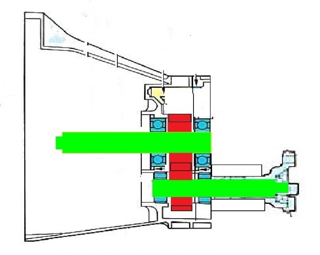
Input shaft is splined both ends 1'' 23 locating on the internal spline of the upper gear, with the lower gear having an prop shaft flange.
Most parts have been re-manufactured, but you will need deep pockets.
Steve
22-04-2014, 08:06 PM
#19
That is exactly how it is done on an RS200, bell housing mounted to the chassis with a continuous mesh transfer box bolted to the back of it.
Input shaft is splined both ends 1'' 23 locating on the internal spline of the upper gear, with the lower gear having an prop shaft flange.
Most parts have been re-manufactured, but you will need deep pockets.
Steve
Input shaft is splined both ends 1'' 23 locating on the internal spline of the upper gear, with the lower gear having an prop shaft flange.
Most parts have been re-manufactured, but you will need deep pockets.
Steve
22-04-2014, 08:18 PM
#20
Looks pretty straight forward you can use for example the same setup crown wheel gear as the focus autos as there straight cut gears with tapered roller bearing holding it in square
The hardest part would be is making a decent casing to hole to 2 gears as they would need to be kept lubricated
The hardest part would be is making a decent casing to hole to 2 gears as they would need to be kept lubricated
22-04-2014, 09:34 PM
#22
Advanced PassionFord User

Didn't see a pump in. Mine when I stripped it years ago
Last edited by jonfoc; 22-04-2014 at 09:37 PM.
22-04-2014, 10:58 PM
#24
mark, ive seen millners reversing transfer box. nice bit of kit and dirt cheap when you see what you get (less than 2k for the basic set up).
However it is a proper transfer box designed for use POST gearbox to distribute the drive to the front and rear diffs. Im looking at doing it all before the gearbox so only need one input and one output rather than 2 outputs.
I guess in theory the diff inside the unit could be replaced with a solid fixed unit and one output blocked off.
All depends if the dimensions and custom modification works out better value than cutting and shutting a mt75 which is dimensionally what i want to suit the clutch issue.

Thread
Thread Starter
Forum
Replies
Last Post
wowk
General Car Related Discussion.
4
30-03-2021 07:49 PM