
Cam Setup

Thread Starter
Brit With A Tan
Joined: Nov 2006
Posts: 271
Likes: 0
From: Miami via Croydon
Hi All
So i want to check that my timing is right on my rebuilt cosworth lump. I was wondering if there are any guides to how to roughtly/ initaly setup the cams before i go it get her properly setup.
Ww
So i want to check that my timing is right on my rebuilt cosworth lump. I was wondering if there are any guides to how to roughtly/ initaly setup the cams before i go it get her properly setup.
Ww
Thread Starter
Brit With A Tan
Joined: Nov 2006
Posts: 271
Likes: 0
From: Miami via Croydon
ok so i am gonna step though the steps here.
http://www.siipicossu.com/manuaaleja/manuaalit.htm
Cosworth Sierra C
Any useful advice or tip, apart from the take it to someone that knows what there doing
http://www.siipicossu.com/manuaaleja/manuaalit.htm
Cosworth Sierra C
Any useful advice or tip, apart from the take it to someone that knows what there doing

20K+ Super Poster.
Joined: Jul 2006
Posts: 24,596
Likes: 4
From: uk
It's a very easy engine to do cam timing wise, but if unsure better to spend a bit to ensure no probs.
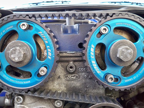
But basically you line up the TDC by the LUG, nearest the "V" groove in bottom pulley being in line with the pointer and the cams pointers facing as you look at them the left hand(exhaust) pointer at 3 o'clock, the right hand(inlet) at 9 o'clock, these will face each other and be in line with the seam between head and rocker cover.
Whilst in this position the scribe mark on the outer edge of the dizzy body with cap/sheild removed must be bang in the centre of the rotor arms path.
Phase sensor gap is 0.2mm to 0.3mm and the crank sensor is 0.6mm to 1.0mm.
tabetha
Thread Starter
Brit With A Tan
Joined: Nov 2006
Posts: 271
Likes: 0
From: Miami via Croydon
Hi Tabetha
Really i would like to get a garage to set it up but i but seems to be able to trust anywhere near me and at the moment the car wont driver till i get the timing done so i need to d a rough setup myself so that i can get her drivable and down to somewhere to get a proper setup.
currently it has some adjustable verniers on but i want to put a spare pair of standard items back on to get her running.
So lets see how we go.
Thread Starter
Brit With A Tan
Joined: Nov 2006
Posts: 271
Likes: 0
From: Miami via Croydon
So now that the crank pulley is set to TDC i noticed that the adjustable pulleys are way out, i think any way.
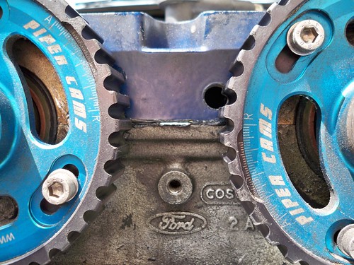
Should both verniers be pointing to each other in the middle of the adjustment marks (halfway between A and R). in effect what the standard pullets do with the pointers.
Also should i set the adjustment back to standard to start with.
Should both verniers be pointing to each other in the middle of the adjustment marks (halfway between A and R). in effect what the standard pullets do with the pointers.
Also should i set the adjustment back to standard to start with.


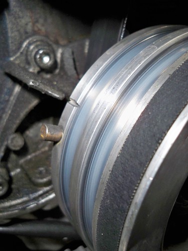
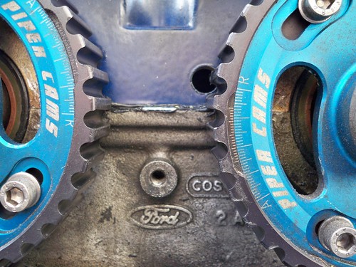
THAT IS NOT TDC !
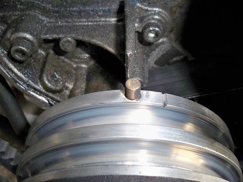
set TDC by lining up the trailing edge of the lug (sticking out of the crank pulley) immediately after the V notch (ie rotate the crank approx 5 degrees clockwise from the position shown in the photo)
set TDC by lining up the trailing edge of the lug (sticking out of the crank pulley) immediately after the V notch (ie rotate the crank approx 5 degrees clockwise from the position shown in the photo)
Trending Topics
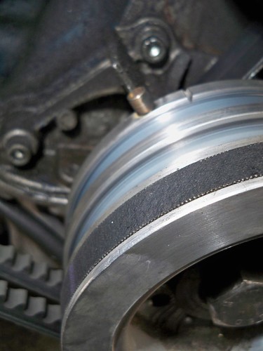
Crank looks fine now.
Taking a guess that the pulleys have been machined so that the centre of adjustment is as per standard pulleys, then I'd say that they're perhaps both out. Try adjusting the pulleys to the centre of the adjustment and have another look.
If you can unbolt the pulleys from the cams (but don't remove them) then as standard the woodruff keys in the ends of the cams should be 180 degrees opposite where the standard pulley alignment marks are - ie the exhaust cam keyway should point to the left, and the inlet cam keyway should point to the right in your photos.
Once you think the cam timing is correct, turn the engine over using a spanner or socket on the crank pulley bolt before turning over on the starter motor. Listen/feel for contact between valves and pistons.
Last edited by jon@work; Jun 20, 2009 at 03:58 PM.
20K+ Super Poster.
Joined: Jul 2006
Posts: 24,596
Likes: 4
From: uk
Another trick is to time up using std cams, then loosen a cam cap, lay a piece of leather on top and tighten down, then mark the cam by the cap so you can see it hasn't moved, replace the std pulleys with the verniers, bit long winded but works 100%.
When you come to fit the verniers just leave the adjustment quite loose so they set/rotate as you tension the belt BEFORE tightening the pulley adjustment bolts.
tabetha
When you come to fit the verniers just leave the adjustment quite loose so they set/rotate as you tension the belt BEFORE tightening the pulley adjustment bolts.
tabetha

PassionFord Regular
Joined: Jul 2003
Posts: 481
Likes: 2
From: nottingham
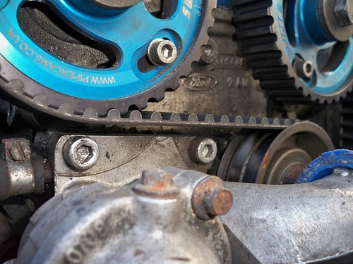
i could be wrong mate but looking at the picture of your cam pullys i think the tensioner has been turned the wrong way when the belt was fitted! it looks very close to the thermostat housing mate, just check to see if the belt is touching and if it is turn the tensioner the other way(clockwise i belive).
cheeRS slarty
cheeRS slarty
Last edited by nicksaph; Jun 20, 2009 at 05:31 PM.
20K+ Super Poster.
Joined: Jul 2006
Posts: 24,596
Likes: 4
From: uk
i could be wrong mate but looking at the picture of your cam pullys i think the tensioner has been turned the wrong way when the belt was fitted! it looks very close to the thermostat housing mate, just check to see if the belt is touching and if it is turn the tensioner the other way(clockwise i belive).
cheeRS slarty
cheeRS slarty
tabetha
Thread Starter
Brit With A Tan
Joined: Nov 2006
Posts: 271
Likes: 0
From: Miami via Croydon
Also i am having real trouble removing the piper vernier so that i can fit the standard one back in. Is there someway of locking them out, so i can get leverage of the vernier?
PassionFord Regular
Joined: Jul 2003
Posts: 481
Likes: 2
From: nottingham
if it is tensioned the wrong way the belt actully touches the housing, mine was like it when i bought it. so i changed it stright away even though the previous owner had just had it replaced befor i bought it
cheeRS nick
Last edited by nicksaph; Jun 20, 2009 at 06:34 PM.
PassionFord Regular
Joined: Jul 2003
Posts: 481
Likes: 2
From: nottingham
a bit butcherous mate but put a screwdriver through the piper pully against the cam cover mating face(be careful not to mark the gasket face or use a thick peice of card or somthing between) or down the side of the head

Thread
Thread Starter
Forum
Replies
Last Post
SMILER258
Restorations, Rebuilds & Projects.
36
Sep 28, 2015 09:04 AM