Electronics experts, need something to stabilise voltage at 9v.
 10-03-2010, 12:36 PM
#1
I have something that I want to run in a car thats effected by varying voltages so I need something that will reduce down whatever voltage the car produces to a steady 9v. So whether the car is 10v or 14v I still want 9v to come out.. Any ideas?
Was looking at these http://uk.rs-online.com/web/search/s...hTerm=686-9751 not sure if thats what I need, lol!
Was looking at these http://uk.rs-online.com/web/search/s...hTerm=686-9751 not sure if thats what I need, lol!
Last edited by Martin-Hadland; 10-03-2010 at 12:39 PM.
 10-03-2010, 12:46 PM
#2
Advanced PassionFord User

Martin,
I fitted a voltage regulator, as you have there to my original Peltor to run it off the car...worked like a charm, fitted into the compartment where the battery used to be.
Ian
I fitted a voltage regulator, as you have there to my original Peltor to run it off the car...worked like a charm, fitted into the compartment where the battery used to be.
Ian
Last edited by ian sibbert; 10-03-2010 at 05:08 PM.
10-03-2010, 12:49 PM
#4
escort mk4 cossy 4x4
Join Date: May 2004
Location: coventry
Posts: 4,629
Likes: 0
Received 0 Likes
on
0 Posts
Voltage Regulator (regulator), usually having three legs, converts varying input voltage and produces a constant regulated output voltage. They are available in a variety of outputs.
The most common part numbers start with the numbers 78 or 79 and finish with two digits indicating the output voltage. The number 78 represents positive voltage and 79 negative one. The 78XX series of voltage regulators are designed for positive input. And the 79XX series is designed for negative input.
Examples:
Note:
As a general rule the input voltage should be limited to 2 to 3 volts above the output voltage. The LM78XX series can handle up to 36 volts input, be advised that the power difference between the input and output appears as heat. If the input voltage is unnecessarily high, the regulator will overheat. Unless sufficient heat dissipation is provided through heat sinking, the regulator will shut down.
does this help?
The most common part numbers start with the numbers 78 or 79 and finish with two digits indicating the output voltage. The number 78 represents positive voltage and 79 negative one. The 78XX series of voltage regulators are designed for positive input. And the 79XX series is designed for negative input.
Examples:
� 5V DC Regulator Name: LM7805 or MC7805
� -5V DC Regulator Name: LM7905 or MC7905
� 6V DC Regulator Name: LM7806 or MC7806
� -9V DC Regulator Name: LM7909 or MC7909
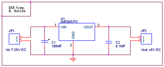
The LM78XX series typically has the ability to drive current up to 1A. For application requirements up to 150mA, 78LXX can be used. As mentioned above, the component has three legs: Input leg which can hold up to 36VDC Common leg (GND) and an output leg with the regulator's voltage. For maximum voltage regulation, adding a capacitor in parallel between the common leg and the output is usually recommended. Typically a 0.1MF capacitor is used. This eliminates any high frequency AC voltage that could otherwise combine with the output voltage. See below circuit diagram which represents a typical use of a voltage regulator. � -5V DC Regulator Name: LM7905 or MC7905
� 6V DC Regulator Name: LM7806 or MC7806
� -9V DC Regulator Name: LM7909 or MC7909
Note:
As a general rule the input voltage should be limited to 2 to 3 volts above the output voltage. The LM78XX series can handle up to 36 volts input, be advised that the power difference between the input and output appears as heat. If the input voltage is unnecessarily high, the regulator will overheat. Unless sufficient heat dissipation is provided through heat sinking, the regulator will shut down.
does this help?

Trending Topics
10-03-2010, 03:13 PM
#9
20K+ Super Poster.

Why not a resistor ?, as you know supply and presumably know theV and current consumption of what you want to power, that's all you need, could use some high power yeageo resistors.
tabetha
tabetha
10-03-2010, 05:04 PM
#11
Professional Waffler
iTrader: (1)
Join Date: May 2003
Location: Cardiff
Posts: 26,931
Likes: 0
Received 0 Likes
on
0 Posts
how about this?
i bought one, as i need something at 1.5v
http://cgi.ebay.co.uk/12V-DC-DC-Conv...item3357962c7a
i bought one, as i need something at 1.5v
http://cgi.ebay.co.uk/12V-DC-DC-Conv...item3357962c7a
10-03-2010, 05:18 PM
#14
The Accuvolt that sheady ran on dave's car is a fantastic bit of kit that will give a fixed voltage output even if you have a lower voltage input, but probably massively overkill for what you want here (ie does it need to still work if the cars voltage goes under 9, im guessing not as your "thing" would be least of your worries by that stage!)
10-03-2010, 05:37 PM
#16
Yes, if you have 2 fixed resistances (ie your item and the resistor) the ratio between the two will stay fixed but the actual value will go up and down with the input.
The Accuvolt that sheady ran on dave's car is a fantastic bit of kit that will give a fixed voltage output even if you have a lower voltage input, but probably massively overkill for what you want here (ie does it need to still work if the cars voltage goes under 9, im guessing not as your "thing" would be least of your worries by that stage!)
The Accuvolt that sheady ran on dave's car is a fantastic bit of kit that will give a fixed voltage output even if you have a lower voltage input, but probably massively overkill for what you want here (ie does it need to still work if the cars voltage goes under 9, im guessing not as your "thing" would be least of your worries by that stage!)
Oops the secrets out!!
Last edited by Martin-Hadland; 10-03-2010 at 05:40 PM.
10-03-2010, 05:47 PM
#17
BANNED
BANNED
iTrader: (1)

Join Date: Jul 2003
Location: Wiltshire
Posts: 12,483
Likes: 0
Received 0 Likes
on
0 Posts
Some real experts here 
A resistor will NOT staibilise the voltage !!!!!!!!!!!!!
Lloyd above has the correct solution
What is this for ?? or if you cant say, what is the maximum current you need ?
I pretty much have all the stuff here to make you what you need martin !
A resistor will NOT staibilise the voltage !!!!!!!!!!!!!
Lloyd above has the correct solution
What is this for ?? or if you cant say, what is the maximum current you need ?
I pretty much have all the stuff here to make you what you need martin !
Last edited by ECU Monitor Enthusiast; 10-03-2010 at 05:52 PM.
10-03-2010, 05:57 PM
#19
Some real experts here
A resistor will NOT staibilise the voltage !!!!!!!!!!!!!
Lloyd above has the correct solution
What is this for ?? or if you cant say, what is the maximum current you need ?
I pretty much have all the stuff here to make you what you need martin !
A resistor will NOT staibilise the voltage !!!!!!!!!!!!!
Lloyd above has the correct solution
What is this for ?? or if you cant say, what is the maximum current you need ?
I pretty much have all the stuff here to make you what you need martin !


 10-03-2010, 07:06 PM
#28
Advanced PassionFord User

Join Date: Feb 2005
Location: Solihull
Posts: 2,090
Likes: 0
Received 0 Likes
on
0 Posts
Only thing I'd add is that the diagram posted earlier shows capacitors of 100MF and 0.1MF - I assume M is meant to stand for micro, as mega farad caps are hard to come by lol! Personally I normally use a 1uf and 0.1uf instead, which will be perfectly adequate unless there are going to be a lot of load transients.
To reduce power dissipation through the regulator at 14.4V, you could use a Zener diode to drop the input voltage to 12.6V.
The ideal solution woud be a charge-pump / dc-dc converter, which is more efficient and can supply at a higher voltage than the input, useful during cranking for example, where with a linear regulator as above the output would drop out.
Chris
10-03-2010, 08:39 PM
#29
BANNED
BANNED
iTrader: (1)
Join Date: Jul 2003
Location: Wiltshire
Posts: 12,483
Likes: 0
Received 0 Likes
on
0 Posts
Chris,
You are correct but I dont have all the componets lying around to build an inverter but I assume martin only needs moderate current and that drop out wont be an issue.
Martin,
I have finished it and tested it upto 2 amps
The heatsnk may need to be made bigger dependng on your application and current requirements.

Due to the unique way that an Iphone is total shite, it took me longer to upload the photo than to build this.
Will stick it in the post tomorrow.

You are correct but I dont have all the componets lying around to build an inverter but I assume martin only needs moderate current and that drop out wont be an issue.
Martin,
I have finished it and tested it upto 2 amps
The heatsnk may need to be made bigger dependng on your application and current requirements.
Due to the unique way that an Iphone is total shite, it took me longer to upload the photo than to build this.
Will stick it in the post tomorrow.
Last edited by ECU Monitor Enthusiast; 10-03-2010 at 08:41 PM.
10-03-2010, 08:43 PM
#30
Chris,
You are correct but I dont have all the componets lying around to build an inverter but I assume martin only needs moderate current and that drop out wont be an issue.
Martin,
I have finished it and tested it upto 2 amps
The heatsnk may need to be made bigger dependng on your application and current requirements.
Due to the unique way that an Iphone is total shite, it took me longer to upload the photo than to build this.
Will stick it in the post tomorrow.
 Just busy trying to read whats on the paperwork on the right
 Last edited by Martin-Hadland; 10-03-2010 at 08:47 PM.
10-03-2010, 08:59 PM
#31
BANNED
BANNED
iTrader: (1)
Join Date: Jul 2003
Location: Wiltshire
Posts: 12,483
Likes: 0
Received 0 Likes
on
0 Posts
LOL, my hand writing is rubbish as in these days of computers I dont do it that often.
Just some random notes and reminders for house hold chores and paperwork.
Just some random notes and reminders for house hold chores and paperwork.
Last edited by ECU Monitor Enthusiast; 10-03-2010 at 09:01 PM.
10-03-2010, 09:10 PM
#33
Chris,
You are correct but I dont have all the componets lying around to build an inverter but I assume martin only needs moderate current and that drop out wont be an issue.
Martin,
I have finished it and tested it upto 2 amps
The heatsnk may need to be made bigger dependng on your application and current requirements.
Due to the unique way that an Iphone is total shite, it took me longer to upload the photo than to build this.
Will stick it in the post tomorrow.
You are correct but I dont have all the componets lying around to build an inverter but I assume martin only needs moderate current and that drop out wont be an issue.
Martin,
I have finished it and tested it upto 2 amps
The heatsnk may need to be made bigger dependng on your application and current requirements.
Due to the unique way that an Iphone is total shite, it took me longer to upload the photo than to build this.
Will stick it in the post tomorrow.
10-03-2010, 09:29 PM
#34
BANNED
BANNED
iTrader: (1)
Join Date: Jul 2003
Location: Wiltshire
Posts: 12,483
Likes: 0
Received 0 Likes
on
0 Posts
LOL eagle eye chipper
You may be right about hiding
Thank fuck it wasnt the page before with all this sites backdoor access details

Thread
Thread Starter
Forum
Replies
Last Post
DavidK
Ford Sierra/Sapphire/RS500 Cosworth
1
27-09-2015 02:55 PM