
FAO Gadget & co,L8 Cossie loom,continuity testing help!


Thread Starter
Advanced PassionFord User
Joined: May 2004
Posts: 1,789
Likes: 0
From: Bexhill, East Sussex
Hello guys,
I've got a Fiesta RS Turbo with a Specialised Engines 1.9 block and L8 Cossie management as fitted by Gadget.
I recently got the car mapped at Grove Garage and all was going well until a few days after getting it back the car developed a major misfire and cut out on me.
I've pretty much tried everything to get the car fixed including replacing the ECU, CPS, fixed CPS bracket and replaced ignition amp, all to no avail.
The problem is the fuel pump and injectors are working when turning the engine over, but there is no spark. Looking at it there's one weak spark upon turning the ignition on and then nothing. We thought it was the ignition amp after removing that and replacing the existing one and the car fired up briefly - but having replaced that today and the problem still existing the car still has the same problem.
I've tried getting in touch with Gary today but haven't got through yet - hopefully he'll reply to my messages, but i was wondering if there was anyone else out there who could possibly help me with this issue.
My apologies to the mods for this being in the wrong section - I'd really like a quick reply on this!
There's a big long post on fiestaturbo.com about this problem explaining the things me and some friends have tried to get this problem fixed...
http://www.fiestaturbo.com/phpBB/viewtopic.php?t=102563
Cheers,
Andy
Thread Starter
Advanced PassionFord User
Joined: May 2004
Posts: 1,789
Likes: 0
From: Bexhill, East Sussex
Originally Posted by Stu @ M Developments
Have you tried unplugging the chip and seeing if it runs?
Failing that, try linking out the choke in the map sensor loom if one is fitted.
Failing that, try linking out the choke in the map sensor loom if one is fitted.
As for the MAP sensor - we borrowed a wiring diagram for L8 Cossie's and checked the pins to the ECU if that's what you're thinking, or do you mean to break the circuit for the choke on the map sensor so it doesn't send a signal to the ECU - if you could explain that a bit more that would be a great help.
The 3bar MAP sensor is a new one as well - bought from yourself in fact last year!
Cheers,
Andy
PassionFords Creator
iTrader: (12)
Joined: May 2003
Posts: 28,824
Likes: 95
From: Blackpool, UK Destination: Rev limiter
Sorry... didnt read that its on cossy management.. what a gimp 
Sounds VERY much like phase sensor.
Have you checked the polarity is correct after folks have messed with it?
The wire nearest the top of teh sensor, goes to the pin nearest to the sensor.
Sounds VERY much like phase sensor.
Have you checked the polarity is correct after folks have messed with it?
The wire nearest the top of teh sensor, goes to the pin nearest to the sensor.
Thread Starter
Advanced PassionFord User
Joined: May 2004
Posts: 1,789
Likes: 0
From: Bexhill, East Sussex
Originally Posted by Stu @ M Developments
Sorry... didnt read that its on cossy management.. what a gimp
Sounds VERY much like phase sensor.
Have you checked the polarity is correct after folks have messed with it?
The wire nearest the top of the sensor, goes to the pin nearest to the sensor.
Sounds VERY much like phase sensor.
Have you checked the polarity is correct after folks have messed with it?
The wire nearest the top of the sensor, goes to the pin nearest to the sensor.
Because of the advice I was given regarding the phase sensor we left that out of our tests.
Cheers,
Andy
Thread Starter
Advanced PassionFord User
Joined: May 2004
Posts: 1,789
Likes: 0
From: Bexhill, East Sussex
Originally Posted by Stu @ M Developments
It would have been my FIRST test im afraid.
They can short internally and cause havoc, and the first clue, is one spark then sod all else.
They can short internally and cause havoc, and the first clue, is one spark then sod all else.
It's just that after repeated trying we managed to get the car running, but then you'd try again and it would do nothing.
Cheers,
Andy
Trending Topics
Thread Starter
Advanced PassionFord User
Joined: May 2004
Posts: 1,789
Likes: 0
From: Bexhill, East Sussex
Originally Posted by Stu @ M Developments
Intermittent is most common.
I dont recall the last one that just broke totally.
I dont recall the last one that just broke totally.
I'm having a crash-course in engine ECU diagnostics starting off with a Weber Marelli L8 Cossie setup in a car that was never designed to have that setup installed!
 Not the best situation as I'm sure you'd agree!
OK - so another sensor to replace then
Any idea on cost of these? I'll get one ordered by a friend who works at Ford.
Cheers,
Andy
Thread Starter
Advanced PassionFord User
Joined: May 2004
Posts: 1,789
Likes: 0
From: Bexhill, East Sussex
Originally Posted by Stu @ M Developments
I charge �25 pal.
And dont worry, you will learn fast
And dont worry, you will learn fast
I'll let you know if it works or not
The AA telephone number is now freshly set as number 1 hotkey on my mobile
Cheers,
Andy
Thread Starter
Advanced PassionFord User
Joined: May 2004
Posts: 1,789
Likes: 0
From: Bexhill, East Sussex
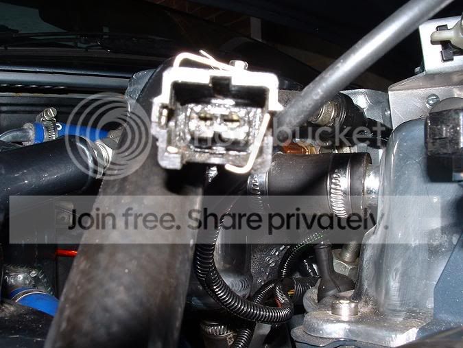
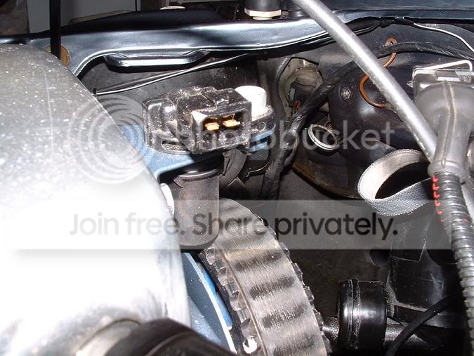
One last question for you Stu - if my phase sensor is fried (which judging by the photos below looks like it is!), should the engine fire up if the phase sensor is disconnected (i.e. removing the short out for testing purposes) or would it not fire up at all without it again (I have disconnected it and the car still won't fire up).
These are the pics of the sensor in place and the phase sensor connector itself, which looks both melted and broken!
Cheers,
Andy
These are the pics of the sensor in place and the phase sensor connector itself, which looks both melted and broken!
Cheers,
Andy
PassionFords Creator
iTrader: (12)
Joined: May 2003
Posts: 28,824
Likes: 95
From: Blackpool, UK Destination: Rev limiter
Its down to the software wether she runs or not, but to throw a spanner in the works thats not a conventional YB phase sensor its a zetec cam sensor and is not as likely to be the problem
Thread Starter
Advanced PassionFord User
Joined: May 2004
Posts: 1,789
Likes: 0
From: Bexhill, East Sussex
Originally Posted by Stu @ M Developments
Its down to the software wether she runs or not, but to throw a spanner in the works thats not a conventional YB phase sensor its a zetec cam sensor and is not as likely to be the problem
It just keeps getting better and better!Man - where the hell is Gadget?
Cheers,
Andy

Generally, on LEVEL 8 ecu's, the phase sensor MUST work in order to initially start the engine.
If it fails during running, then the engine ususally continues to run.
If the fuel pump runs when cranking, the crank sensor is ok.
To check the phase sensor,
Re connect it !
Check with a resistance meter, pins 5 and 23 should read between 500 and 1200 ohms.
(ECU removed)
Switch the meter to AC volts, crank the engine and you should see an intermittent voltage of around 1.5 to 5 volts
while cranking the engine.
Good advice: NEVER run the car WITHOUT the phase sensor connected !!
Thread Starter
Advanced PassionFord User
Joined: May 2004
Posts: 1,789
Likes: 0
From: Bexhill, East Sussex
Yeah - one weak spark when turning the ignition on and then nothing when turning the engine over.
Injectors are firing and fuel pump cuts off as well - have replaced the CPS with new one.
Ignition amp replaced, coil has been tested and works fine, ECU was replaced and Pectel board swapped over from my old ECU as we suspected that the injector drivers weren't working on 2 and 3 but I think that was because the ECU was going through the startup process on the 4x4 Sapphire Cossie we tested it on.
I'll have a go with the multimeter on the phase sensor and ECU side of the phase sensor tomorrow, had enough with the car today.
Cheers,
Andy

Regular Contributor
Joined: Oct 2003
Posts: 199
Likes: 0
From: South East (Essex)
it sounds suspiciously like a tacho wire fault! 
Try chcking the ohms resistance in the green wire on the back of your dials to where it plugs into the coil. see what reading you get.
Try chcking the ohms resistance in the green wire on the back of your dials to where it plugs into the coil. see what reading you get.
Thread Starter
Advanced PassionFord User
Joined: May 2004
Posts: 1,789
Likes: 0
From: Bexhill, East Sussex
Originally Posted by Philly
it sounds suspiciously like a tacho wire fault!
Try chcking the ohms resistance in the green wire on the back of your dials to where it plugs into the coil. see what reading you get.
Try chcking the ohms resistance in the green wire on the back of your dials to where it plugs into the coil. see what reading you get.
So what impedance should I be looking at with the rev counter wire?
What would the issue be with this wire?
Cheers,
Andy
Regular Contributor
Joined: Oct 2003
Posts: 199
Likes: 0
From: South East (Essex)
not another one!!
I just spoke to some other dude whos got the same thing! EFi clocks, whats it all about?
Well you want a little resistance as possible 0.01 would be nice, but that aint ever gonna happen on a 15 year old bit of wire!
should be looking for 0.03-0.06 or something?
if you dont get a reading at all then theres a break in the wire!
Thread Starter
Advanced PassionFord User
Joined: May 2004
Posts: 1,789
Likes: 0
From: Bexhill, East Sussex
Originally Posted by Philly
not another one!!
I just spoke to some other dude whos got the same thing! EFi clocks, whats it all about?
Well you want a little resistance as possible 0.01 would be nice, but that aint ever gonna happen on a 15 year old bit of wire!
should be looking for 0.03-0.06 or something?
if you dont get a reading at all then theres a break in the wire!
I just spoke to some other dude whos got the same thing! EFi clocks, whats it all about?
Well you want a little resistance as possible 0.01 would be nice, but that aint ever gonna happen on a 15 year old bit of wire!
should be looking for 0.03-0.06 or something?
if you dont get a reading at all then theres a break in the wire!
As for EEC-IV clocks - the reason is that EEC-IV uses wasted spark, the other spark which is 'wasted' is used to send the rpm signal back to the ECU and also to the rev counter. Effectively this signal is half the signal you'll get from an older coil type system (like Weber Cossie management) which sends out a spark for every rpm of the engine, so send coil signal to EEC-IV clocks and it thinks the engine is doing double the rpm it actually is.
Simple enough really - I have the correct clock to replace it (hopefully), using a coil non EDIS rev counter, gonna have to bugger about with the soldering on the back though as the contact points are different.
I'll have to try the green wire out tomorrow.
Cheers,
Andy
Thread Starter
Advanced PassionFord User
Joined: May 2004
Posts: 1,789
Likes: 0
From: Bexhill, East Sussex
Originally Posted by Philly
And trust me it happens! 
and its the last thing you will ever expect it to be!
good luck anyway! let us know the outcome yeah?
and its the last thing you will ever expect it to be!
good luck anyway! let us know the outcome yeah?
Cheers,
Andy

Thread Starter
Advanced PassionFord User
Joined: May 2004
Posts: 1,789
Likes: 0
From: Bexhill, East Sussex
The advice you gave is the same regardless of car though - there is a green wire which comes from the coil itself to the rev counter, we plugged it in knowing it would double read and if you split it in half it's working correctly.
However, that doesn't mean that there isn't a problem with the rpm signal wire going from the coil to the ECU, wherever it may split off (I think it's pretty close to the coil itself).
Anyone else know anything more about that?
Cheers,
Andy
However, that doesn't mean that there isn't a problem with the rpm signal wire going from the coil to the ECU, wherever it may split off (I think it's pretty close to the coil itself).
Anyone else know anything more about that?
Cheers,
Andy
Thread Starter
Advanced PassionFord User
Joined: May 2004
Posts: 1,789
Likes: 0
From: Bexhill, East Sussex
Originally Posted by Philly
YEP STILL THE SAME!
CHECK IT!
CHECK IT!
Cheers,
Andy
Thread Starter
Advanced PassionFord User
Joined: May 2004
Posts: 1,789
Likes: 0
From: Bexhill, East Sussex
Originally Posted by SECS
RPM signal on cossie managment comes DIRECTLY from the coil negative.
Sometimes VIA an inline filter.
Sometimes VIA an inline filter.
I'll go and give this wire a check over, I'm off now to push the car back out of the garage so I can work on it using what light is left!
Cheers,
Andy
Thread Starter
Advanced PassionFord User
Joined: May 2004
Posts: 1,789
Likes: 0
From: Bexhill, East Sussex
Right - where the wire enters into the loom it feels a bit wobbly loose like the wire is broken inside after being bent back and forth too many times. I'll have a check with the multimeter now and see if it goes in and out of open circuit, would explain why fiddling around with the ignition amp and wiring (which is all cable tied up with the coil wiring) caused the engine to fire up last night only to cut out again.
Cheers,
Andy
Cheers,
Andy
Spanner monkey
Joined: May 2003
Posts: 3,556
Likes: 14
From: Peterborough
Andy,
I have replied to your PM,
What the hell has happened the the Cam sensor and the plug ??? they look like they have been burn't????
I have mailed you a wiring diagram for the cossie loom, hopefully it may be helpfull!!
This is one wierd fault, hope you can get to the bottom of this asap!!
I have replied to your PM,
What the hell has happened the the Cam sensor and the plug
??? they look like they have been burn't????I have mailed you a wiring diagram for the cossie loom, hopefully it may be helpfull!!
This is one wierd fault, hope you can get to the bottom of this asap!!
Thread Starter
Advanced PassionFord User
Joined: May 2004
Posts: 1,789
Likes: 0
From: Bexhill, East Sussex
Originally Posted by Gadget
Andy,
I have replied to your PM,
What the hell has happened the the Cam sensor and the plug ??? they look like they have been burn't????
I have mailed you a wiring diagram for the cossie loom, hopefully it may be helpfull!!
This is one wierd fault, hope you can get to the bottom of this asap!!
I have replied to your PM,
What the hell has happened the the Cam sensor and the plug
??? they look like they have been burn't????I have mailed you a wiring diagram for the cossie loom, hopefully it may be helpfull!!
This is one wierd fault, hope you can get to the bottom of this asap!!
The day I picked the car up from them they said the car wouldn't start up as if the CPS was disconnected but it miraculously solved itself.
The CPS, ignition amp, coil and other things have been checked but I didn't do any checks on the phase sensor as Grove said it wouldn't be that!
For whoever it was who told me the voltages for the phase sensor when the engine is running - any idea what the voltage is per rpm as I'm only able to turn the engine over by starter motor at 200-250rpm (maybe less).
Anyway - to say I'm fed up with the car is an understatement.
Cheers,
Andy
Thread Starter
Advanced PassionFord User
Joined: May 2004
Posts: 1,789
Likes: 0
From: Bexhill, East Sussex
Bit of an update - taking the whole engine loom out of the car now and I've got as far as removing all the sensor connectors etc.


I now just need to remove the connectors up to the fuse box (ignition live and fuel pump) so hopefully it will be out by this evening.
Cheers,
Andy
I now just need to remove the connectors up to the fuse box (ignition live and fuel pump) so hopefully it will be out by this evening.
Cheers,
Andy
Thread Starter
Advanced PassionFord User
Joined: May 2004
Posts: 1,789
Likes: 0
From: Bexhill, East Sussex
Right - the ECU loom is out of the car now 

I want to start testing the car out tomorrow but the pin-out diagram's I'm being sent will not arrive here until Tuesday, so if any of you out there have a copy of the diagram available electronically then please let me know.
My e-mail address is andrewalanhardy@hotmail.com or PM us on here

Cheers,
Andy
I want to start testing the car out tomorrow but the pin-out diagram's I'm being sent will not arrive here until Tuesday, so if any of you out there have a copy of the diagram available electronically then please let me know.
My e-mail address is andrewalanhardy@hotmail.com or PM us on here
Cheers,
Andy
Spanner monkey
Joined: May 2003
Posts: 3,556
Likes: 14
From: Peterborough
Andy, i mailed the diagram to your andrewalanhardy@hotmail.com addy??
did you not get it? i was a level 6 diagram but its only the tps wires that are opposite to each other and the crank sensor has had the live and the trigger wires swapped as they it is an eec sensor, same for the crank sensor!!
did you not get it? i was a level 6 diagram but its only the tps wires that are opposite to each other and the crank sensor has had the live and the trigger wires swapped as they it is an eec sensor, same for the crank sensor!!