
Saff cossie 4x4 abs wiring diagram

Thread Starter


Joined: Jul 2006
Posts: 62,772
Likes: 1,050
From: Darlington county durham
Has anyone got a wiring diagram for the 4x4 cossie abs system. Im sure there was one on here a few weeks ago. I just cant find it.
Thread Starter
Joined: Jul 2006
Posts: 62,772
Likes: 1,050
From: Darlington county durham
which relays are for the abs. Is it the 2 purple ones. The abs light is just coming straight on when the ignition is switched on. Does the abs pump only prime up when the car is first started. I had this fault a few months ago,i had a look at the relays n fuses and abs ecu. The light went off and i thought i had fixed it.
The pump primes when the system pressure drops below 105 BAR, pumping the pedal with ignition on should run the pump though (As does it when your driving along).
Jon@work is the person to speak to.
It does sound like a sensor issue tbh, btw the system is exactly the same as used on Lesser models and Granadas if needing parts, diagrams etc (Tevas)
Martin
Jon@work is the person to speak to.
It does sound like a sensor issue tbh, btw the system is exactly the same as used on Lesser models and Granadas if needing parts, diagrams etc (Tevas)
Martin
Trending Topics
Thread Starter
Joined: Jul 2006
Posts: 62,772
Likes: 1,050
From: Darlington county durham
The pump primes when the system pressure drops below 105 BAR, pumping the pedal with ignition on should run the pump though (As does it when your driving along).
Jon@work is the person to speak to.
It does sound like a sensor issue tbh, btw the system is exactly the same as used on Lesser models and Granadas if needing parts, diagrams etc (Tevas)
Martin
Jon@work is the person to speak to.
It does sound like a sensor issue tbh, btw the system is exactly the same as used on Lesser models and Granadas if needing parts, diagrams etc (Tevas)
Martin
Thread Starter
Joined: Jul 2006
Posts: 62,772
Likes: 1,050
From: Darlington county durham
Yeh i was thinking that. I had a fault with the osf abs sensor last year. The light used to go off then when i started to drive the car the light would come on.

PassionFord Post Troll
Joined: Sep 2004
Posts: 2,823
Likes: 8
From: Colchester
Any idea what the black plug and the white plug and the wires do?
i suspect they have something to do with the sapphire cosworth dash ?
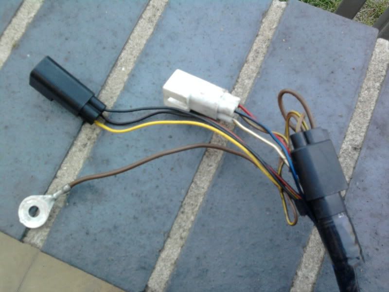
Can anyone fill in the blanks of what each wire does???
BLACK PLUG :
black wire -
yellow wire -
black / red striped wire -
WHITE PLUG :
black/blue wire -
red wire -
brown with yellow striped wire -
yellow with white striped wire -
i suspect they have something to do with the sapphire cosworth dash ?
Can anyone fill in the blanks of what each wire does???
BLACK PLUG :
black wire -
yellow wire -
black / red striped wire -
WHITE PLUG :
black/blue wire -
red wire -
brown with yellow striped wire -
yellow with white striped wire -


Too many posts.. I need a life!!
Joined: Jun 2005
Posts: 704
Likes: 1
From: Watford
Too many posts.. I need a life!!
Joined: Jun 2005
Posts: 704
Likes: 1
From: Watford
this may be of use
ELECTRO-VALVE TESTS
All tests performed with ABS ECU unplugged and ignition switched OFF unless stated otherwise.
Resistance Test 1
-- Connect ohmmeter between ECU connector terminals 1 and 11
-- Resistance should be lower than 1 ohm
-- If value is not correct, check for continuity between ECU connector terminal 11 and electro-valve connector terminal 7 (brown wire), and check that terminal 7 on the electro-valve (corresponding with the brown wire) is earthed.
Resistance Test 2
-- Connect ohmmeter between ECU connector terminals :
11 and 15
11 and 17
11 and 35
11 and 33
11 and 16
11 and 34
-- Resistance for each electro-valve should be between 3 and 7 ohms.
-- If not, remove connector from electro-valve, and check resistance between the following electro-valve terminals (the brown wire is terminal 7):
1 & 7 (LH front inlet valve)
2 & 7 (LH front outlet valve)
3 & 7 (rear inlet valve)
4 & 7 (rear outlet valve)
5 & 7 (RH front outlet valve)
6 & 7 (RH front inlet valve)
-- If one of the values is not correct (3 to 7 ohms), replace electro-valve/master cylinder assembly.
-- If the values are correct, check for continuity between control electro-valve connector and ECU connector.
ABS ECU connector terminal 15 & electro-valve terminal 1
ABS ECU connector terminal 34 & electro-valve terminal 2
ABS ECU connector terminal 17 & electro-valve terminal 3
ABS ECU connector terminal 33 & electro-valve terminal 4
ABS ECU connector terminal 16 & electro-valve terminal 5
ABS ECU connector terminal 35 & electro-valve terminal 6
Operation Test
IMPORTANT : Do not energize electro-valves for more than 60 sec.
-- Jack up vehicle to turn wheels.
-- Switch Ignition to position I
-- Wait for ABS pump to stop
-- Switch ignition OFF
-- Connect short jumper wire between ECU connector terminals 2 & 8
-- To test left front wheel valves, connect short jumper wires between ECU connector terminals 3 and 16 and 35. Depress brake pedal to lock wheel. If ignition now switched to position II, wheel should be free to rotate.
-- Repeat test for right front wheel, using short jumper wires between ECU connector terminals 3 and 15 and 34.
-- Repeat test for rear wheels, using short jumper wires between ECU connector terminals 3 and 17 and 33.
-- If one of these checks is not correct, but the wiring checks out OK, replace electro-valve assembly.

15000
Joined: Nov 2009
Posts: 27
Likes: 0
From: Barbados

SIERRA RS 4X4 COSWORTH
Joined: Dec 2008
Posts: 673
Likes: 6
From: NORTH LONDON/Co .Antrim
SIERRA RS 4X4 COSWORTH
Joined: Dec 2008
Posts: 673
Likes: 6
From: NORTH LONDON/Co .Antrim
My old memory says check the simple stuff .. connectors loose ? under rear seat corners and front chassis legs tops is there locations ....
Waggle test .. to check for them at the fail limit on connectors ... from memory they should resistance check .8 ohm to 1.4ohm as a running range
Fluid level just wrong ( Pump brake pedal 30 times to de-pressurise- ign off , switch ign on system let system it pressure up =True level) or fluid boiling losing brake losing pressure
Warped discs all, cv joints funky on front 4x4 ... all sensor heads clean ? no rust sticking to them, pick up rings corroded .. remove sensors carefully
 they snap at the hubs
 Goodluck

Typing fast as off out


Virgin
Joined: Dec 2010
Posts: 3
Likes: 0
From: bulgaria

Thread
Thread Starter
Forum
Replies
Last Post
DixieTheKid
Ford Sierra/Sapphire/RS500 Cosworth
7
Jul 23, 2023 10:16 AM
Anutternutter
Ford Sierra/Sapphire/RS500 Cosworth
2
Aug 21, 2015 06:07 PM
mrmann
Restorations, Rebuilds & Projects.
1
Aug 20, 2015 11:24 PM