It has struck me that other than the Cossie brake upgrade, there is a question that keeps on getting asked day after day!
"What do I need to convert my MFi RS Turbo to run EFi?"
I propose a Sticky thread on a "Basic" conversion using OFAB or OFAC.
I've done a lot of research into this as I plan to do this conversion myself. Before I start here's a quick list of my references:
www.rsbible.co.uk - Very descriptive, good pictures and diagrams.
www.extraefi.co.uk - A good EDIS diagrams
www.passionford.com Our friendly Forum
www.dainst.com lots of EDIS info
www.megamanual.com - Lots more on EDIS
Other sites I may have to add!
Here's my 2p's worth feel free to add, remove or CONSTRUCTIVELY criticise:
You will need:
1) CVH EFi Head (XR2i or Fiesta RS Turbo) or MFI>EFI sandwich plate.
2) Complete EFi inlet (Inlet manifold, throttle body, injectors, fuel rail, pressure regulator, Throttle position sensor, Idle speed control valve and injector wiring loom)
3) ECU and engine Loom (OFAB or OFAC, loom to suit) An XR3i EFi loom can be used with OFAC.
4) Electronic Distributorless Ignition System (EDIS-4 unit, Crank Position Sensor and Coilpack).
5) Suitable HT Leads.
6) Some form of Crank Position Sensor pickup, either:
.....a) A drilled block and EFi flywheel.
.....b) Sierra CVH crank and alternator pulleys with sierra CVH lower timing belt cover and ribbed aux belt.
.....c) A N Other 36-1 tooth trigger wheel on the crank with Crank Position Sensor bracket (Oddkid creations have been mentioned).
7) MAP sensor (ECU Specific).
8) CO2 Potentiometer.
9) Vehicle Speed sensor.
10) Fuel hose from fuel filter to fuel rail.
11) Engine sensors for the ECU type chosen.
12) XR2i or XR3i EFI throttle pedal and throttle cable.
13) Fiesta RS Turbo rocker cover and charge carrier (ERST ones may be used but a bit fiddly).
14) OFAB will need a MAP sensor suppressor
You won't need:
1) XR3i EFi Dash pod and rev counter. Contrary to popular belief you don't need an XR3i EFi Rev counter. If you intend to keep the wiring as it is, the standard output is from pin 10 of the EDIS which is one of the 2 coil drive outputs. This will obviously only give you half the reading of the current revs which the XR3i EFi rev counter can interperate correctly but the S2 one can't as it would need an input from both coil drive outputs. To overcome this you have two options:
A) Add an output to pin 11 of the EDIS which is its CTO (Clean Tacho Output). There is no pin on the EDIS connector at pin 11 on the XR3i loom and I'm not sure about the FRST loom but one can be easily added. You can just drill a small hole through the back section of the casing, steal a pin from a spare EDIS connector and push it through.
This method doesn't often work!
B) Build a tacho adapter by following this diagram:
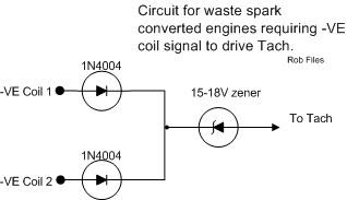 Credit for this image to www.locostbuilders.co.uk
Either of these methods can then be run as far as the RPM suppressor and plugged directly into the green cable running to the dash bypassing the suppressor and the output from pin 10.
A few things to note:
1) If you want to run anything other than standard settings, the relevant chip and injectors are required (165/195chip, Bosch "beige" 701 injectors).
2) If you want to run more than 1 bar (14.5 psi) of boost, you will have to use an alternative MAP sensor. For OFAB you can use a Cosworth 3 bar MAP sensor which can measure up to 2 bar of boost (1 bar atmospheric pressure and 2 bar positive boost). For OFAC, you can use a Small Turbo Escort Cosworth MAP sensor. This sensor is a 2.5 bar item (1 bar atmospheric pressure and 1.5 bar positive boost).
3) If you want to use an XR3i EFi car & engine loom (1AfA) whith OFAC there are usually no pinout changes. On some installations you will need to check that the CO pot goes to the correct pin for your ECU, some are 8, some are 27. This will need confirmation with a gas analyser.
4) You may get a seemingly low reading from the rev counter. If so you may get away with running a wire from pin 11 of the EDIS module as described above, if not, build your own tacho adapter.
5) If you use the Sierra 1.8 CVH crank pulley you will need the Sierra 1.8 CVH alternator bracket. This bracket needs 5mm machined off the one side to align it with the crank pulley. You will also need a 5mm washer (As sold by Oddkidd creations) to fit between the crank pulley and the retaining bolt.
How to with FRST loom:
I wont make this a full step by step, that would be dificult as there are a few diferent scenarios and would take forever. If you have chosen the correct loom for the ECU then no pinout changes need to be made (Obviously). Thus making neither OFAB nor OFAC harder than eachother.
1) Disconnect the battery!
2) Fit all of your mechanical parts.
3) Fit all of your sensors.
4) Tape back the parts of the original loom not required. Once finished and tested you can cut out and remove any parts of the loom not required if you like.
5) Install the EFi engine loom.
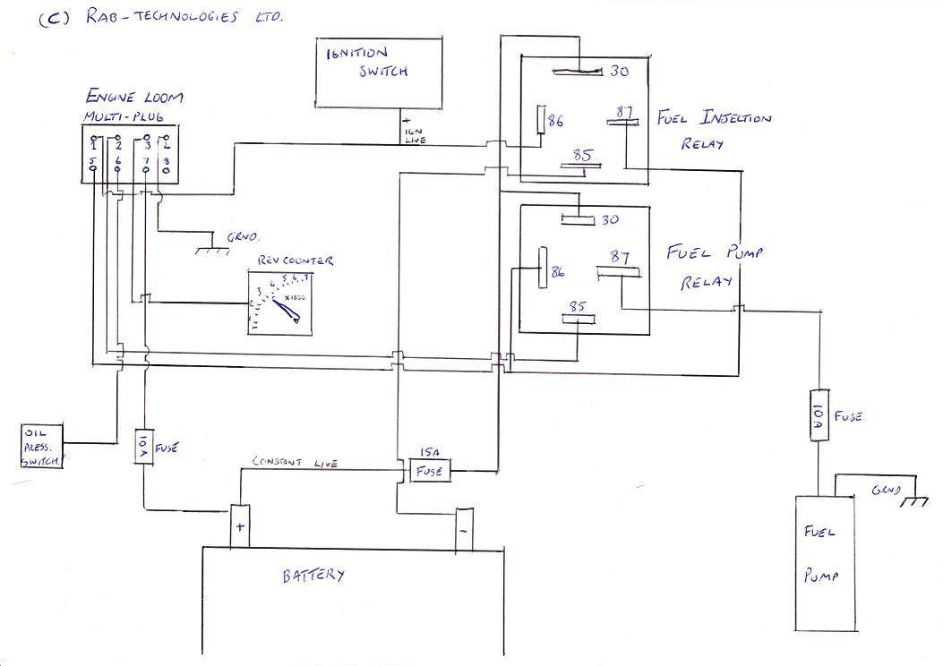
6) Connect the engine loom to the car loom. You will need to do a bit of chopping and changing. This bit can be tricky, but I will re-post this diagram by passionford member
Rab as I think it shows it quite well:
7) Run a wire from the rev counter input to pin 11 of the EDIS-4 unit or by using the tacho adapter above.
8) Connect up the engine loom to the sensors, cooling Fan, ECU, coilpack, Idle speed control valve and EDIS (Some wires may need to be extended eg. Fan and ISCV).
9) Double check everything!
10) Cross your fingers and fire up the car!
If you use the loom from an EFi XR3i it's even easier, just fit the loom to the car, plug in an OFAC ECU and MAP sensor and you're away. That's my plan:
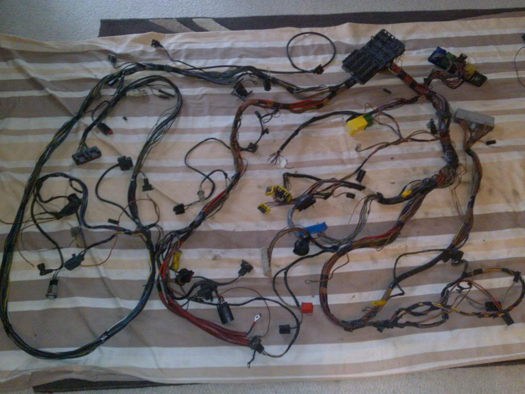
One almost complete loom, just needs a trial fit and taping up.
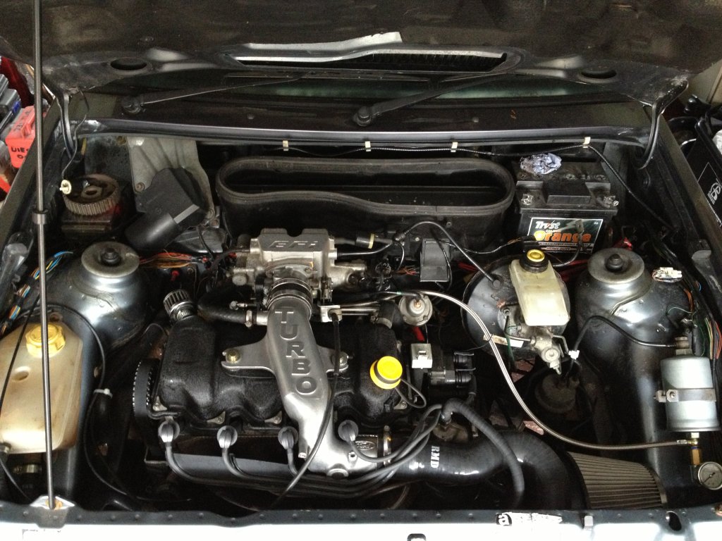
For the fuel system, i have left the MFi accumulator and fuel filter in place. From the fuel filter I have a braided hose going over to the fuel rail. To acomodate a fuel pressure gauge I have utilised one of these banjo bolts from Burton Power:
Click Here, I then drilled it out right through the midle and have attached my gauge to the M10 end like so:
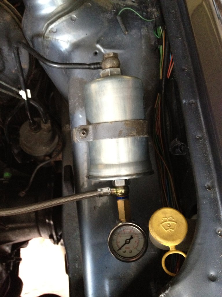
And with a bit of luck, you'll end up with a bay like this:
I'm not claiming this is complete, but it should answer most of the repetitive questions! and a big thanks to everyone for the info I've gathered.
Edit 05/05/2013:
Setting up
• The CPS needs to be very close to the trigger wheel, we're taking 1mm
• The fuel pressure needs to be set to suit the spec.
The original FPR is adjustable, you just need to remove the silver circular tab covering the adjustment screw (This is on the top of the FPR), then the pressure can be adjusted acordingly
• A stage 2 (195 spec) engine needs around 3.5 Bar of fuel pressue with the engine running and the vacuum line removed from the FPR
• Don't forget to use a pressure gauge when setting the fuel pressure.
Troubleshooting tips
• The EDIS module should have 12v ignition live to pin 8 and should have earth to pin 9, the XR3i EFi loom has the earth ring termination down by the horn.
• All 3 pins on the coil harness should have positive 12v with the ignition on and the engine off, the edis switches the outer 2 pins to earth to fire the coil
• To test the coil, you should get about 3-6Ω resistance across the middle pin and one outer pin of the coil's loom connector and 13-16KΩ across 2 common lead posts (I.e. 1&4 or 2&3)
• To test the CO Pot, look at the connector holding it with the adjustment screw pointing upwards, put your multimeter across pins 1 and 2. You should get readings of between 0.5-5.5Ω. My CO Pot doesn't go from point to point, it just keeps tuning but doesn't go beyond those readings.
• Lumpy idle when warm could be due to a faulty ISCV. The issue I had was I removed the breather system in favour for a mini K&N on the rocker cover; bad move. There are two vacuum ports on the lower inlet manifold, these take in fresh air and vapours from the breather system for idle!
• Chipped ECU's will give you ECU error codes when using a code reader. You will get something similar to:
A) 53 Throttle Position sensor above maximum voltage
B) 72 MAP, MAF or BP sensor out of range during Dynamic Response Test
C) 59 CO potentiometer error
You may also receive checksum errors.
Edit 07/06/2013:
There's been quite a debate recently about rev counters, some saying that pin 11 of the EDIS worked for them, others saying it didn't. Well, for those that it doesnt work, the circuit below shows how to set up a direct feed from the coil drives to your rev counter:
Credit for this image to www.locostbuilders.co.uk
Edit 17/07/2013:
Well, there's been a lot of mention recently about pin changes on the XR3i EFi loom for use with OFAC. There seems to be a few variations of looms out there. Mine is a late spec EFi loom and all the pins were correct. For other looms some pin changes are required, as detailed by Karlos on this thread:
1afa - ofac
Originally Posted by
Karlos G
If anyone is interested this is the wire swaping you need to do for XR3i/XR2i (1AFA) to FRST (OFAC)...
1) Pin no. 8 (brown) needs moving to pin 27, which is empty (CO adjuster signal wire)
2) Pin no. 27 (brown/yellow) needs moving to pin no. 45
3) EDIS Module pin 2 (blue/yellow) may now be disregarded as it is not used by the 0FAC ECU (pin 28 on ECU).
There are no MAP sensor pin changes as the OFAC MAP sensor is the same plug as the 2i MAP Sensor, so just plug and play.
But... only on some conversions it seems!

Some work plug and play and others need the above doing, maybe there are some subtle differences in the ECU/loom's of different years I don't know?! But I guess if it doesn't work one way then try it the other! lol
Karlos.
Basically,
you will need to check that the CO signal wire goes to the correct pin for your ECU, this will need confirmation with a gas analyser. Also check that the MAP signal wire goes to pin 45.
Edit 17/08/2013:
I can confirm that using pin 11 of the EDIS for my Tacho signal didn't work for me. I've had to use the diode circuit above. The good news is it works well. I've also set the CO% level to 1.5% as per the Haynes manual so now the car is ready for an MOT!
Edit 05/04/2014:
It's been a while! Good news is the cabby now has an MOT! I sorted out my base idle issue which I've added to the troubleshooting section above.
Edit 20/06/2014:
I've finally had the cabby dyno'd and all is well. Made a decent amount of horsepower at 10psi boost with a nice torque curve to match. However, it didn't all go to plan to begin with. It was a figment of my imagination (and partly to do with my Gunson Gastester) that the CO pot was located on the correct ECU pin. Contrary to popular beleif, my CO pot didn't work at all on pin 27, and had to be moved to pin 8. The thread has been updated above.
Lee
