
Rev counter


Thread Starter
15000
Joined: Feb 2016
Posts: 29
Likes: 0
From: Fife

Hi guys i know this has been covered a few times i am trying to get mine working with the coil pack on gotech , i have piggybacked into the wires on the coil pack (2outer wires) with the dioads as the picture i found on here but the car misses and pops on idle when they are wired in ? Any ideas ? Cheers
Last edited by L33_srd; Oct 28, 2016 at 10:48 AM.

Bring back old skool Ford
Joined: Feb 2010
Posts: 137
Likes: 3
From: Northern Ireland
I tried this to get my rev counter working after going Zetec as it only reads around half revs. May be i used the wrong type diodes or somethin but the car wouldnt even start with them connected!
Not sure how people have made this work, would be intersted to find out
Not sure how people have made this work, would be intersted to find out
PassionFord Post Whore!!


Joined: Aug 2004
Posts: 3,502
Likes: 184
From: Colchester,essex
I adjusted the pot on the rev counter itself (strip the clocks down, pot lives on the top at the back of the tacho unit). Pain to strip and get to but my circuit similar to above didnt work either.

I've found that life I needed.. It's HERE!!
Joined: Sep 2005
Posts: 1,329
Likes: 7
From: South East
By following the diagram 
It definitely works, I've used it on several cars.
2x 1N4004
1x 1N4744 (Zener)
The only reason it would missfire is if one or more of the diodes were the wrong way round.
Like this, but without the big blue pullup resistor:
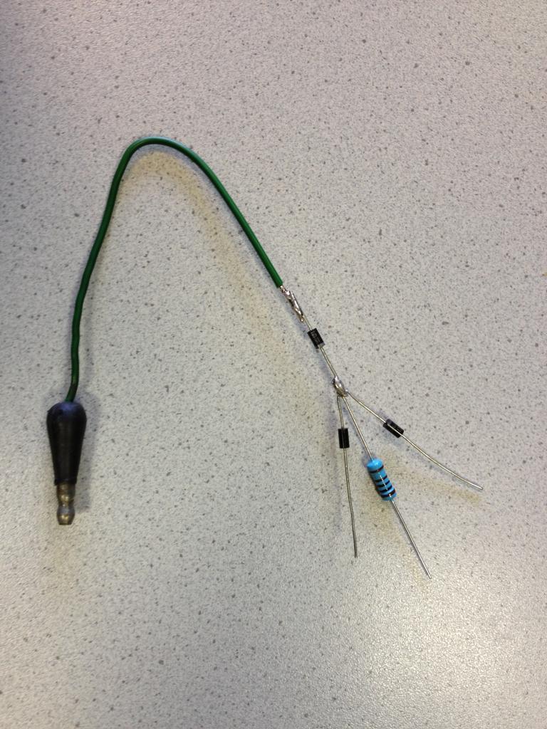
All of the stripes on the diodes face each other. Green wire in the pic is connected to the 1N4744 Zener and goes off to the tacho (original bullet connector retained for ease of install, make the join near the EDIS). Tail of each 1N4004 diode go to one coil each (piggyback one to the cable on pin 10 of the EDIS and one to pin 12). Ignore the blue pullup resistor it's not required.
Lee
It definitely works, I've used it on several cars.
2x 1N4004
1x 1N4744 (Zener)
The only reason it would missfire is if one or more of the diodes were the wrong way round.
Like this, but without the big blue pullup resistor:
All of the stripes on the diodes face each other. Green wire in the pic is connected to the 1N4744 Zener and goes off to the tacho (original bullet connector retained for ease of install, make the join near the EDIS). Tail of each 1N4004 diode go to one coil each (piggyback one to the cable on pin 10 of the EDIS and one to pin 12). Ignore the blue pullup resistor it's not required.
Lee
Last edited by mentalasanything; Oct 30, 2016 at 06:46 PM.
Trending Topics
Thread Starter
15000
Joined: Feb 2016
Posts: 29
Likes: 0
From: Fife
By following the diagram
It definitely works, I've used it on several cars.
2x 1N4004
1x 1N4744 (Zener)
The only reason it would missfire is if one or more of the diodes were the wrong way round.
Like this, but without the big blue pullup resistor:

All of the stripes on the diodes face each other. Green wire in the pic is connected to the 1N4744 Zener and goes off to the tacho (original bullet connector retained for ease of install, make the join near the EDIS). Tail of each 1N4004 diode go to one coil each (piggyback one to the cable on pin 10 of the EDIS and one to pin 12). Ignore the blue pullup resistor it's not required.
Lee
It definitely works, I've used it on several cars.
2x 1N4004
1x 1N4744 (Zener)
The only reason it would missfire is if one or more of the diodes were the wrong way round.
Like this, but without the big blue pullup resistor:
All of the stripes on the diodes face each other. Green wire in the pic is connected to the 1N4744 Zener and goes off to the tacho (original bullet connector retained for ease of install, make the join near the EDIS). Tail of each 1N4004 diode go to one coil each (piggyback one to the cable on pin 10 of the EDIS and one to pin 12). Ignore the blue pullup resistor it's not required.
Lee
I will give it another bash when im home from work see how it goes , i piggybacked them at the coil pack connection as my ecu is inside the car but i dont see why that would make any difference 👍