


mechanical/electronic wasted spark ignition system


Thread Starter
Part of the Furniture
Joined: Oct 2013
Posts: 165
Likes: 0
From: Antwerp Belgium
 mechanical/electronic wasted spark ignition system
Hello everybody
I am going to try ( as a project ) to make a mechanical/electronic wasted spark ignition system.
That means keeping the rotor and dizzy but not adapting the software or ECU.
Only use for the dizzy and rotor will determine the position of the crankshaft.
It’s using an optical reflection sensor who’s detecting the position of the rotor. This is going to drive an DIY electronic circuit that’s dividing the ECU spark timing signal to two power switch transistors with dwell regulation and two coils ( one for plug 1 and 4 , one for plug 3 and 2 ) for the 4 sparks.
So no need for the expensive ECU adaptation kit and software , only the electronic circuit and the wasted spark coil.
Anybody has tried already to go this way ?
Grts
Patrick
I am going to try ( as a project ) to make a mechanical/electronic wasted spark ignition system.
That means keeping the rotor and dizzy but not adapting the software or ECU.
Only use for the dizzy and rotor will determine the position of the crankshaft.
It’s using an optical reflection sensor who’s detecting the position of the rotor. This is going to drive an DIY electronic circuit that’s dividing the ECU spark timing signal to two power switch transistors with dwell regulation and two coils ( one for plug 1 and 4 , one for plug 3 and 2 ) for the 4 sparks.
So no need for the expensive ECU adaptation kit and software , only the electronic circuit and the wasted spark coil.
Anybody has tried already to go this way ?
Grts
Patrick

Thread Starter
Part of the Furniture
Joined: Oct 2013
Posts: 165
Likes: 0
From: Antwerp Belgium
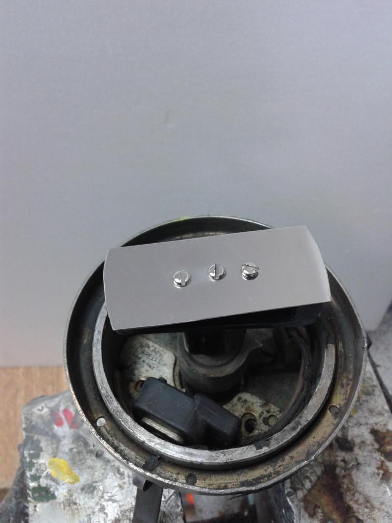
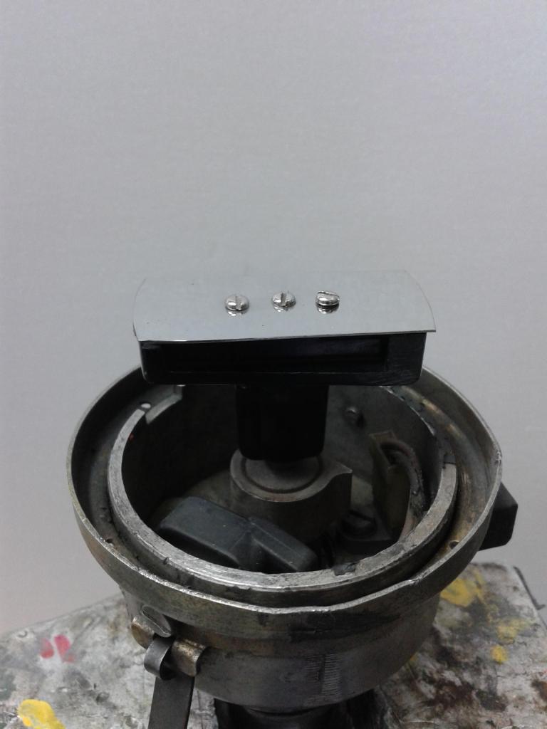
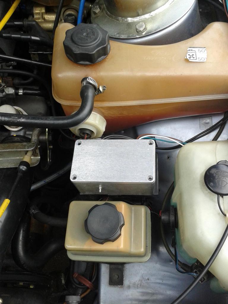
Made a little bracket to put the module on and adapted the rotor.
[IMG]https://passionford.com/forum/<a href=http://s1008.photobucket.com/user/cauf61/media/20140913_101855_zps0975ec5b.jpg.html target=_blank>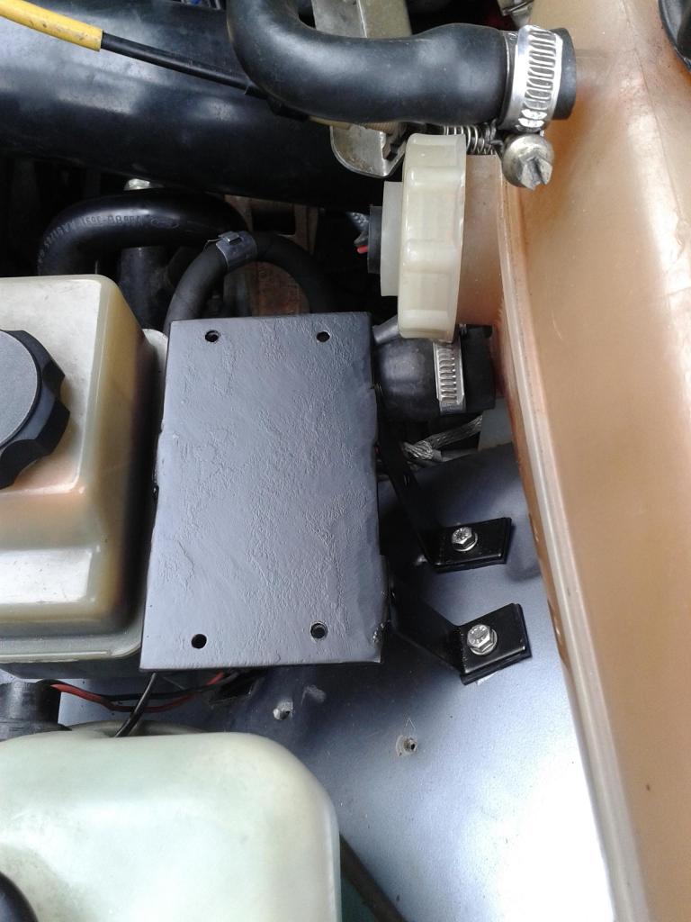
[IMG]https://passionford.com/forum/<a href=http://s1008.photobucket.com/user/cauf61/media/20140913_101820_zps33a61a14.jpg.html target=_blank>
[IMG]https://passionford.com/forum/<a href=http://s1008.photobucket.com/user/cauf61/media/20140913_123239_zps91f16fb4.jpg.html target=_blank>
[IMG]https://passionford.com/forum/<a href=http://s1008.photobucket.com/user/cauf61/media/20140913_101855_zps0975ec5b.jpg.html target=_blank>


[IMG]https://passionford.com/forum/<a href=http://s1008.photobucket.com/user/cauf61/media/20140913_101820_zps33a61a14.jpg.html target=_blank>
[IMG]https://passionford.com/forum/<a href=http://s1008.photobucket.com/user/cauf61/media/20140913_123239_zps91f16fb4.jpg.html target=_blank>
Last edited by Cauf61; Sep 13, 2014 at 06:12 PM.
Thread Starter
Part of the Furniture
Joined: Oct 2013
Posts: 165
Likes: 0
From: Antwerp Belgium
The stainless piece is polished to max reflection.
Make everything as symetrical as possible to not disturb the balance of the rotor.
Use the same 3 screws.
It's turning at 3000 rpm.
The dimensions are not super critical as it's just needed to indicate which set of cylinders to fire. 1 and 4 or 2 and 3.
I made it the same width as the largest part of the rotor.
Exact timing is done by ECU and stays as standard.
Make everything as symetrical as possible to not disturb the balance of the rotor.
Use the same 3 screws.
It's turning at 3000 rpm.
The dimensions are not super critical as it's just needed to indicate which set of cylinders to fire. 1 and 4 or 2 and 3.
I made it the same width as the largest part of the rotor.
Exact timing is done by ECU and stays as standard.
Thread Starter
Part of the Furniture
Joined: Oct 2013
Posts: 165
Likes: 0
From: Antwerp Belgium
Glued in the reflection sensor.
It's a ir led diode and transistor.
As you can see it's in line with a HT connection.
I used an old dizzy cap and cut out the HT connections.
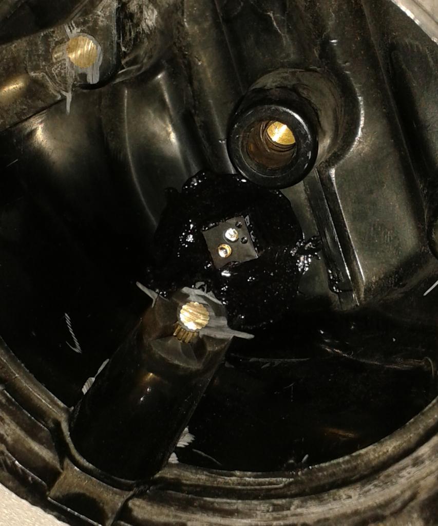
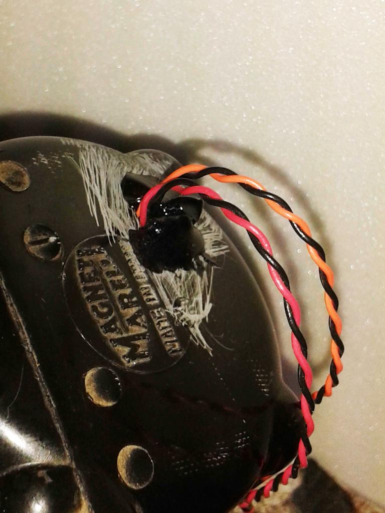
It's a ir led diode and transistor.
As you can see it's in line with a HT connection.
I used an old dizzy cap and cut out the HT connections.


Last edited by Cauf61; Sep 18, 2014 at 06:07 PM.
Thread Starter
Part of the Furniture
Joined: Oct 2013
Posts: 165
Likes: 0
From: Antwerp Belgium
The first test whent fine.
On the picture you see the ignition signal divided in to two signals for the two coils.
It's the position of the rotor thats send the signal ( and spark ) to cyl 1 and 4 or 2 and 3.
The timing is not altered and produced by the marelli ECU.
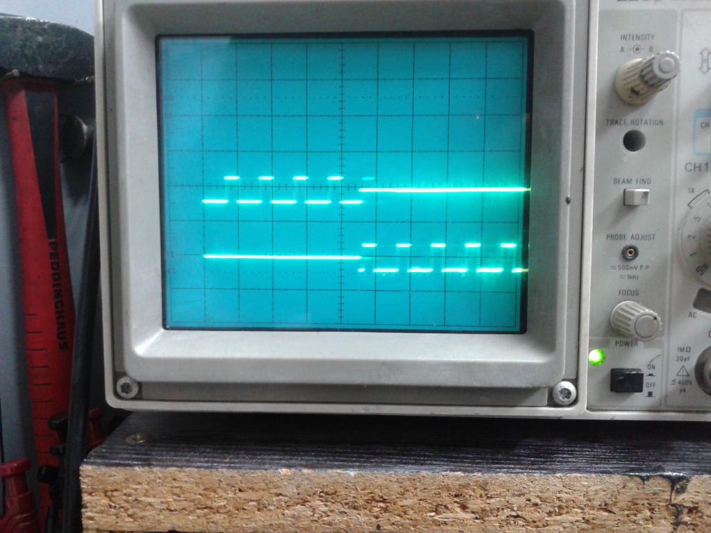
On the picture you see the ignition signal divided in to two signals for the two coils.
It's the position of the rotor thats send the signal ( and spark ) to cyl 1 and 4 or 2 and 3.
The timing is not altered and produced by the marelli ECU.


Trending Topics
 mechanical
not being critical but the more accepted method of wasted spark does away with the use of the dizzy/mechanics of it,you still need it for your system..
will you see a far stronger spark than a group a coil/fresh leads and cap?
do you think it will be as good as the normally available double amplifier kit with modded ecu?
will be good to see your results
will you see a far stronger spark than a group a coil/fresh leads and cap?
do you think it will be as good as the normally available double amplifier kit with modded ecu?
will be good to see your results

Thread
Thread Starter
Forum
Replies
Last Post
deathrider666
Technical help Q & A
3
Sep 28, 2015 06:12 PM