
megasquirt in combination with rev counter problem


Thread Starter
I've found that life I needed.. It's HERE!!
Joined: Aug 2006
Posts: 1,063
Likes: 0
From: The Netherlands
Hello guys,
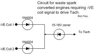
I have the following problem. As I run megasquirt on my CVH I had to fix the rev counter input. I did it according to the scheme of topic "What do I need to convert my MFi RS Turbo to run EFi? Updated 05/04/14 "

My lay out is following. The -VE coil 1 and 2 are connected to the megasquirt and as well to the diodes as above. The wire that says to tach goes to the green wire on the blue connector of the dials and to the middle pin of the fuel relais.
What happens now is that with the blue connector on the dials I get 5 volt, with running engine, on the +15 (12V with key on, 0V with key off) when the key is out! If I take the blue connector of it drops to zero.
Also it makes the car run bad, so clearly something goes wrong.
I also followed the scheme on this one, but don't know what kind of input the tach wants to see.
Any thoughts on this? Is my explanation clear?
I have the following problem. As I run megasquirt on my CVH I had to fix the rev counter input. I did it according to the scheme of topic "What do I need to convert my MFi RS Turbo to run EFi? Updated 05/04/14 "
My lay out is following. The -VE coil 1 and 2 are connected to the megasquirt and as well to the diodes as above. The wire that says to tach goes to the green wire on the blue connector of the dials and to the middle pin of the fuel relais.
What happens now is that with the blue connector on the dials I get 5 volt, with running engine, on the +15 (12V with key on, 0V with key off) when the key is out! If I take the blue connector of it drops to zero.
Also it makes the car run bad, so clearly something goes wrong.
I also followed the scheme on this one, but don't know what kind of input the tach wants to see.
Any thoughts on this? Is my explanation clear?
Thread Starter
I've found that life I needed.. It's HERE!!
Joined: Aug 2006
Posts: 1,063
Likes: 0
From: The Netherlands
I am also running the MFI counter and if I read it correct this is also what the diagram above is made for. I do not have a tacho output on my megasquirt yet as I thought I could do it directly from the coil. So I hope you could hook me up with the diagram you used!
Last edited by Red_bull; May 16, 2014 at 01:50 PM.

I've found that life I needed.. It's HERE!!
Joined: Sep 2005
Posts: 1,329
Likes: 7
From: South East
Also, have you got the diodes the correct way round?
I run that circuit on mine an it works fine. Connect the two -ve to each side of the coil and the "to tach" to the green wire only.
Lee

Thread Starter
I've found that life I needed.. It's HERE!!
Joined: Aug 2006
Posts: 1,063
Likes: 0
From: The Netherlands
The fuel relay needs a tacho input on the middle pin to run the fuel pump when the engine runs. So I can't disconnect that one. Do you have the original relay?
Diodes are the right way around, but it looks like I don't see the first 1500rpm or something. Maybe the 15V zener that I took is still too high?
Anyway the problem got more strange
My battery wasn't charging, because my blue connector on the dials was off, so I decided to disconnect the tacho signal to there (as the reading was bad I assumed this caused the problem). Put the blue connector back on and now it kept running again with 5 Volt on it with and without the blue connector.
We started to measure where the 5V came from with running engine and key out and found that the black and yellow wire from the blue connector had 5 volt on it. Traced it down to the fusebox. Brake pedal fuse connected to this one. Started it again, took key out, hit the brake, engine off.
What feedback does the brakepedal send to the dials? The tacho signal present or not present does change the problem. I deff have a problem somewhere in my wireing, but I don't know where.
For now the black and yellow wire is cut and everything seems to work fine. But I would like to trace the problem.
I've found that life I needed.. It's HERE!!
Joined: Sep 2005
Posts: 1,329
Likes: 7
From: South East
The fuel relay needs a tacho input on the middle pin to run the fuel pump when the engine runs. So I can't disconnect that one. Do you have the original relay?
Diodes are the right way around, but it looks like I don't see the first 1500rpm or something. Maybe the 15V zener that I took is still too high?
Anyway the problem got more strange
My battery wasn't charging, because my blue connector on the dials was off, so I decided to disconnect the tacho signal to there (as the reading was bad I assumed this caused the problem). Put the blue connector back on and now it kept running again with 5 Volt on it with and without the blue connector.
We started to measure where the 5V came from with running engine and key out and found that the black and yellow wire from the blue connector had 5 volt on it. Traced it down to the fusebox. Brake pedal fuse connected to this one. Started it again, took key out, hit the brake, engine off.
What feedback does the brakepedal send to the dials? The tacho signal present or not present does change the problem. I deff have a problem somewhere in my wireing, but I don't know where.
For now the black and yellow wire is cut and everything seems to work fine. But I would like to trace the problem.
Diodes are the right way around, but it looks like I don't see the first 1500rpm or something. Maybe the 15V zener that I took is still too high?
Anyway the problem got more strange
My battery wasn't charging, because my blue connector on the dials was off, so I decided to disconnect the tacho signal to there (as the reading was bad I assumed this caused the problem). Put the blue connector back on and now it kept running again with 5 Volt on it with and without the blue connector.
We started to measure where the 5V came from with running engine and key out and found that the black and yellow wire from the blue connector had 5 volt on it. Traced it down to the fusebox. Brake pedal fuse connected to this one. Started it again, took key out, hit the brake, engine off.
What feedback does the brakepedal send to the dials? The tacho signal present or not present does change the problem. I deff have a problem somewhere in my wireing, but I don't know where.
For now the black and yellow wire is cut and everything seems to work fine. But I would like to trace the problem.
I don't run the pink relay, that may be one of your issues.
Lee
Trending Topics
PassionFord Post Whore!!


Joined: Aug 2005
Posts: 8,349
Likes: 207
From: at home
the engine running with the key off is because you need a diode on the alternator, mine does it. Can't be bothered fixing it but will do one day. Google megasquirt running witk key out.
Thread Starter
I've found that life I needed.. It's HERE!!
Joined: Aug 2006
Posts: 1,063
Likes: 0
From: The Netherlands
Hello Lee,
Thanks for that info, but can you maybe explain electrical why I get the problem now?
What kind of signal does the tacho want to see? And why is it shitty cause the fuel pump wire?
Thanks for that info, but can you maybe explain electrical why I get the problem now?
What kind of signal does the tacho want to see? And why is it shitty cause the fuel pump wire?
Thread Starter
I've found that life I needed.. It's HERE!!
Joined: Aug 2006
Posts: 1,063
Likes: 0
From: The Netherlands
Will I be able to fix both problems with a 1N4001 diode or do I need to get something better then that? I dunno if the peak voltages are getting higher then 50 volts
I've found that life I needed.. It's HERE!!
Joined: Sep 2005
Posts: 1,329
Likes: 7
From: South East
I can't speak for the engine running with the key out issue, as I've never used megasquirt, but for the fuel pump relay Tacho connection I'd use a 1n4004 as used above in the Tacho adapter. What Zenner did you use out of interest? I used a 1n4744.
My theory behind the reason you're getting the issue is that the Tacho signal is a pulsed negative signal. That's been connected to a relay that drives your pump but you don't know what internal connections that relay pin has. It could pull to earth, it's probably connected to something that's interfering with your signal.
Have you thought about re-wiring the fuel pump relay as described in the EFi sticky? This is the most common way to wire it in an EFi conversion and that would remove the requirement for a Tacho signal to the relay all together.
Lee
Last edited by mentalasanything; May 20, 2014 at 03:38 PM.
Thread Starter
I've found that life I needed.. It's HERE!!
Joined: Aug 2006
Posts: 1,063
Likes: 0
From: The Netherlands
I used a BZX 83C 15V zener diode. I think I will switch to a normal relay and bin the standard fuel pump relay. As you said I don't know the connections inside and it is giving me a headache!
I made a typo I ment the 1n4004 I did it out of my head. I thought I used these
I made a typo I ment the 1n4004
I did it out of my head. I thought I used these
Thread Starter
I've found that life I needed.. It's HERE!!
Joined: Aug 2006
Posts: 1,063
Likes: 0
From: The Netherlands
So i got an update (told you it was gonna take a while). I had to resolder my megasquirt, but i got the fuelpumpcircuit to work from that one too now. So the purple relay is out of the car. There is not FP connection with the rev counter anymore, but i still have the same problem.
I had a look with a scope and the rev counter just sometimes jumps into place and sometimes dives down. This while the signal stays the same. I don't see a sudden loss of signal and i am measuring it just before it goes into the car (so i am measuring under the bonnet). Still planning to measure right before it goes into the cockpit, but didn't have enough time yet.
Can anybody say if the behavior i see is normal for a broken rev counter? Because the signal does not change only rev counter does, so i am expecting a broken rev counter?
Hi There,
Its been a very long time since my car used a standard coil and dizzy, did the standard tacho connect directly to the coil? (if not ignore the next bit!).
If it did (and some cars do) you can try removing the zener and replacing it with a resisor of between 330R and 1K, the zener is not actually there to limit voltage to 18V, it is there to block the 12V present at steady state. Further, the IN4004 diodes will not really conduct well into an open circuit (which you effectively have with the zener there).
An alternatve approach would mean adding a resistor of between 1 and 10K after the two IN4004 diodes to ground BEFORE the zener, this will allow current to flow through the IN4004's properly and should allow the zener to break down as you expect.
Your other option is to swap to an EFI rev counter and drive via the ecu OR drive the MFI rev counter via a relay coil from the ecu tach output, as far as I know this is how Karl does it and he has converted more RST's to MS than anyone else I can think of!
If you get stuck I can draw you some pictures.
Best of luck
Rob,

Thread
Thread Starter
Forum
Replies
Last Post