Timing Belt
Removal
NOTE: Timing belt and injection pump belt should not be removed/installed until engine is cold (stopped for at least 4 hours).
Mondeo - remove:
Engine undershield.
RH lower inner wing panel.
Escort - remove:
PAS reservoir. Disconnect return hose only (if fitted).
Coolant expansion tank.
All models - remove:
Auxiliary drive belt(s).
Alternator cover (if fitted).
Alternator/bracket (if required).
PAS pump pulley (if fitted to injection pump).
PAS pump (if required). DO NOT disconnect hoses.
Fiesta 1996→/Mondeo:
Support front of engine.
Remove RH engine mounting.
Fiesta 1996→ - remove:
Crankshaft pulley bolts (4 bolts).
Crankshaft pulley.
All models - remove:
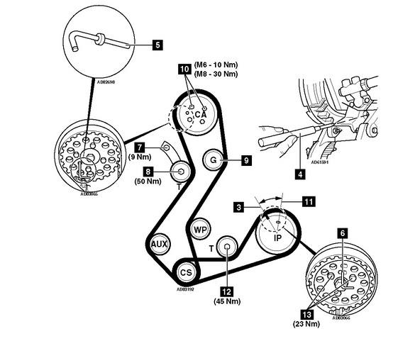
Timing belt covers Fig.10399.1 & Fig.10399.2.
Injection pump belt cover (Fiesta 1996→).
Turn crankshaft clockwise until slot in injection pump sprocket at 11 o'clock Fig.10399.3.
Remove blanking plug from cylinder block. Insert timing pin in cylinder block Fig.10399.4. Tool No.21-104.
Turn crankshaft clockwise until it stops against timing pin.
Insert timing pin in camshaft sprocket Fig.10399.5. Tool No.23-019.
Insert timing pin in injection pump sprocket Fig.10399.6. Tool No.23-019.
NOTE: Engines fitted with CAV injection pump: Insert 6 mm drill bit in injection pump sprocket Fig.10399.6.
Slacken tensioner hexagon bolt and Torx bolt Fig.10399.7 & Fig.10399.8.
Move tensioner away from belt. Lightly tighten bolt Fig.10399.8.
Remove timing belt.
NOTE: DO NOT refit used belt.
Installation
NOTE: Refer to Ford dealer for revised timing belt lower cover, to prevent debris entering timing belt drive area.
Check tensioner pulley and guide sprocket for cracks, chips or other damage. Replace if necessary.
NOTE: If guide sprocket Fig.10399.9 is plastic, it should be replaced with a steel sprocket No.7053802 and bolt No.6701537.
Spin tensioner pulley and guide sprocket. Check for bearing roughness and noise. Replace if necessary.
NOTE: If tensioner bolt Fig.10399.8 has 'mushroom' head, check for evidence of removal with a chisel or self-grip wrench. If so, fit a new bolt and tensioner.
Ensure timing pin located correctly in camshaft sprocket Fig.10399.5.
Ensure timing pin or 6 mm drill bit (CAV) located correctly in injection pump sprocket Fig.10399.6.
Ensure crankshaft web against timing pin Fig.10399.4.
Fit timing belt. Slack side of belt must be towards tensioner. Observe direction of rotation marks on belt.
Slacken camshaft sprocket bolts Fig.10399.10.
Slacken injection pump sprocket bolts Fig.10399.13.
Slacken tensioner bolts 1/2 turn Fig.10399.7 & Fig.10399.8. Allow tensioner to operate.
Tighten camshaft sprocket bolts Fig.10399.10.
Tighten injection pump sprocket bolts Fig.10399.13.
NOTE: Ensure bolts not at end of slotted holes in sprockets.
Tighten tensioner bolts Fig.10399.7 & Fig.10399.8.
Remove timing pins Fig.10399.4, Fig.10399.5 & Fig.10399.6.
Turn crankshaft two turns clockwise. Ensure injection pump sprocket slot at 12 o'clock Fig.10399.11.
Turn crankshaft anti-clockwise until injection pump sprocket slot at 11 o'clock Fig.10399.3.
Insert timing pin in cylinder block Fig.10399.4. Turn crankshaft clockwise until it stops against timing pin.
Insert timing pin in camshaft sprocket Fig.10399.5.
Insert timing pin or 6 mm drill bit (CAV) in injection pump sprocket Fig.10399.6.
Slacken camshaft sprocket bolts Fig.10399.10.
Slacken injection pump sprocket bolts Fig.10399.13.
Slacken tensioner bolts Fig.10399.7 & Fig.10399.8.
Push tensioner firmly against belt and release.
Tighten tensioner bolts to specified torque Fig.10399.7 & Fig.10399.8.
Tighten camshaft sprocket bolts to specified torque Fig.10399.10.
Tighten injection pump sprocket bolts to specified torque Fig.10399.13.
Remove timing pins Fig.10399.4, Fig.10399.5 & Fig.10399.6.
Install components in reverse order of removal.