So we initially used corrugated oem looking flexi pipe for the internal return and reg in the tank. However with the run we used it developed pin holes and was misting fuel during a pressure test. Back to rubber hosing it was. Will did look for a 4 bar oem pressure reg to fit in the bottom of the pump module to no avail so the solution we have come up with incorporates a 280lph walbro style pump fitted into the standard housing with the tea bag filter in the correct place. That then feeds the to donut fuel rail in the top of the module that can supply the HPFP via the standard fuel lines in the car. The return from the donut then comes through the side of the module and on to the Reg (the loop outside the module as shown was cut and the reg was inserted)which returns fuel to lift area of the module (should prevent any fuel starvation when the tank level is low). Reg was set at 4 bar and then thread locked in place and the boost compensation blanked off as its not needed with DI. We also wired the new pump to the original wiring with some nifty cool seal crimps.
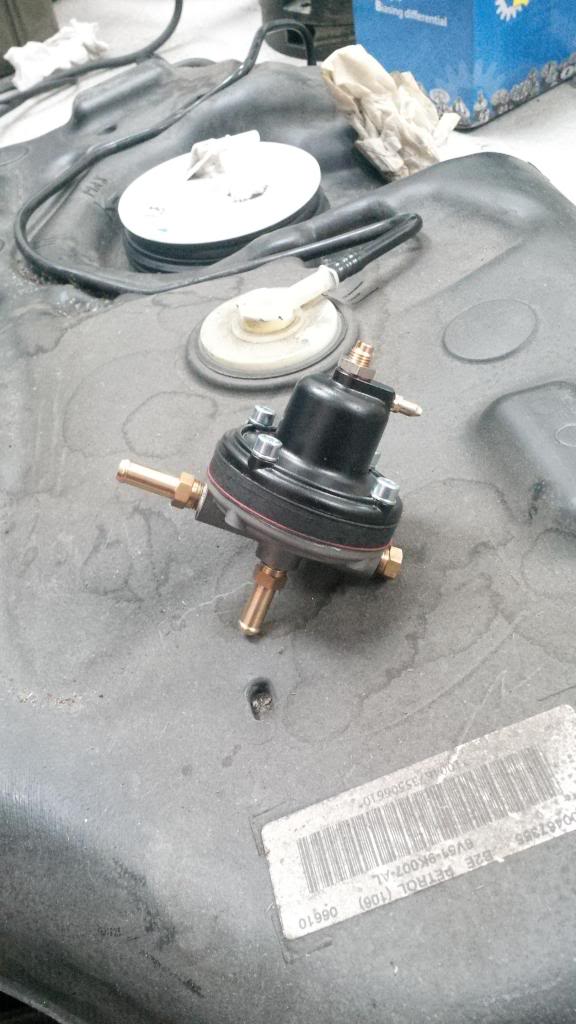
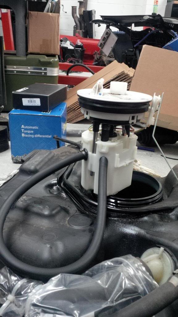
The reg was then hooked into the tank with enough line to put it right over in the corner and the module locked into its standard position. A quick shake test suggests we have no rattle and zero clips are doing a great job of holding all the lines on the barbs. We could then refit the tank and attached all of the OEM connectors and lines.
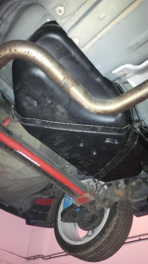
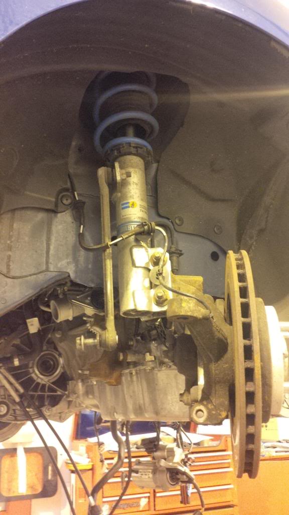
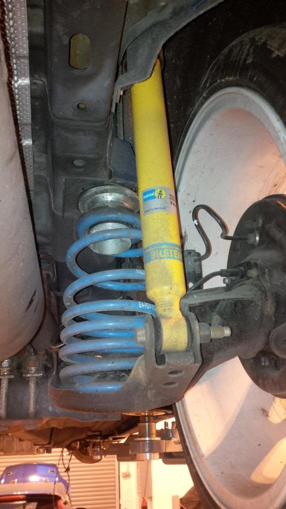
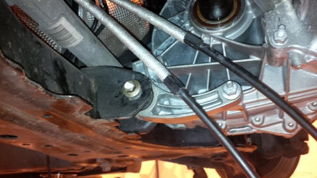
nice view of the racing beat rear ARB there as well.
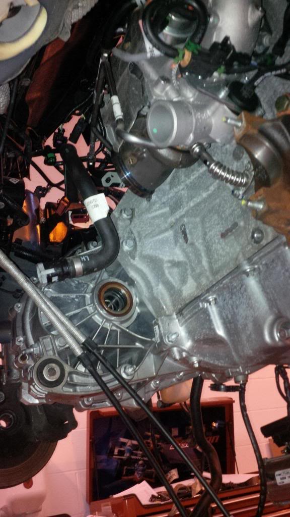
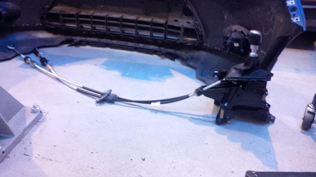
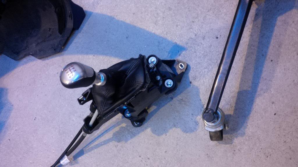
Whilst the subframe was off after the welding got a few pictures of the engine hung in place and also took some of the new shifter and cables which are going to be a nightmare to feed through the bulkhead thanks to the low slung heater matrix. (if anyone has any experience of this and any advice please let me know).
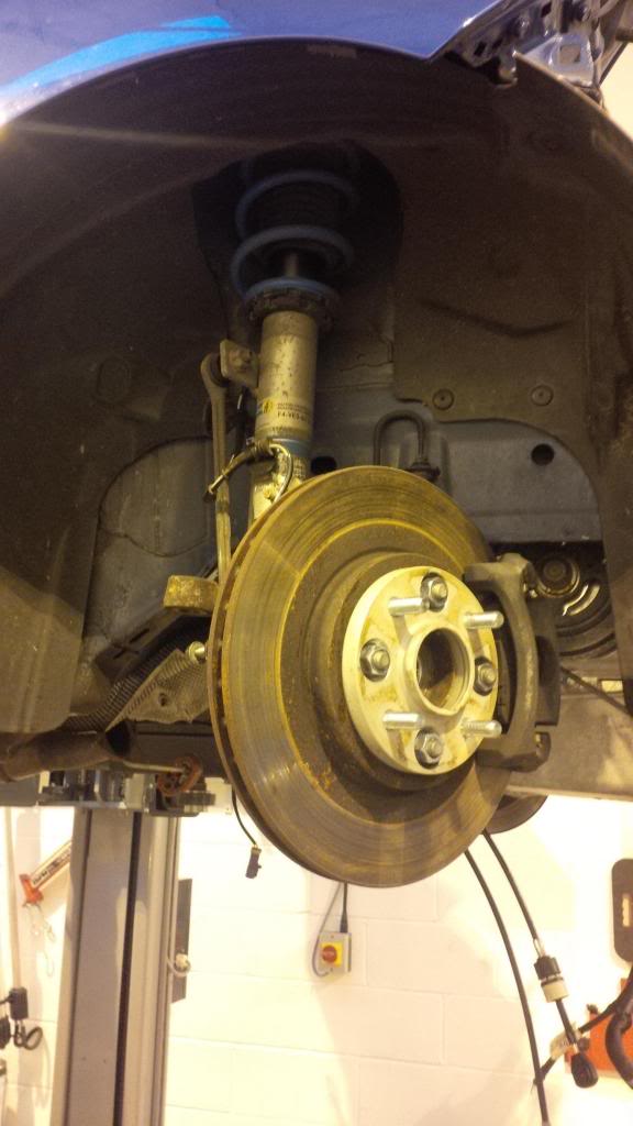
I thought id get some of the suspension whilst it was stripped down as i hadn't took many when i did the initial install.
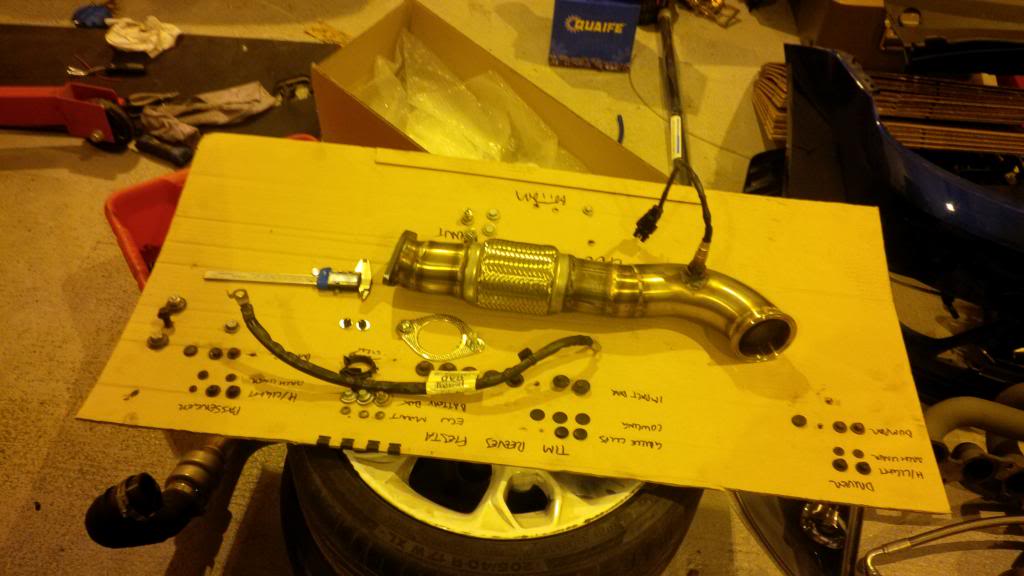
And here's how everybody should store bolts when working on your car so that you know exactly where they are and where they came from!
From there we weren't happy with the battery tray so we put the subframe on to make sure everything was in place reused the OEM battery tray and in three hours did a better job than the fabricators managed in three months -.-
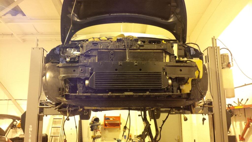
I then hung the front cradle on just to have a look at some spacing and what not whilst the subframe and all was attached.
We have ordered a shoulder bolt for the torque link so that we get the correct fit and just need to get some spacers turned for either side of the rubber.
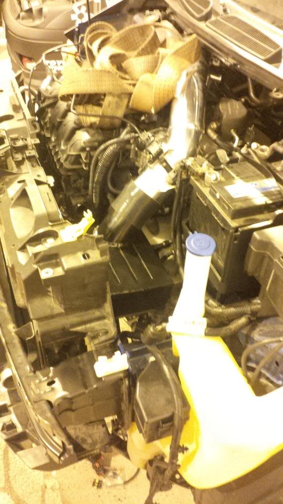
Pretty tight between the front of the engine and the rad (but the cradle wasn't fully pushed forward here which gave another 10mm or so) but enough for a decent slimline fan!
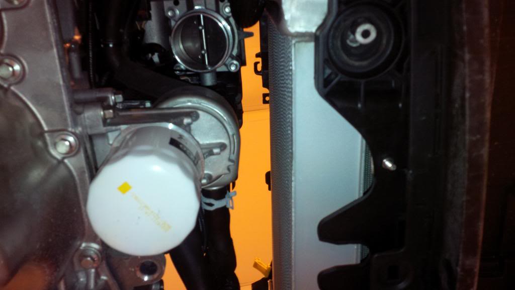
getting a bit packed in there now.
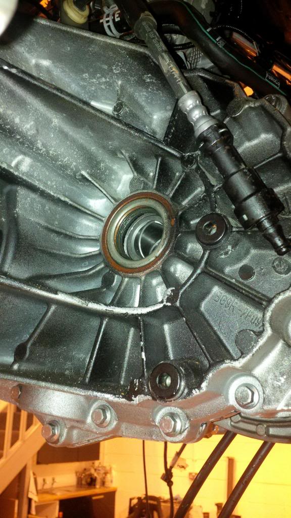
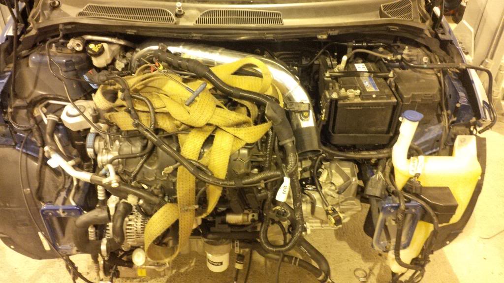
and then finally had chance to put all the bolts back in the gearbox and put the starter motor back on and plug a lot of the loom in to tidy it up and have a reccy of where we are actually at.
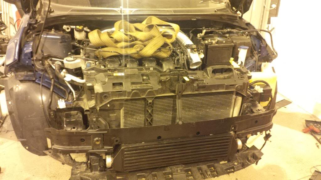
Also had a look at the airbox position with the new pipe, new battery tray and the cradle on and its pretty tight in there.
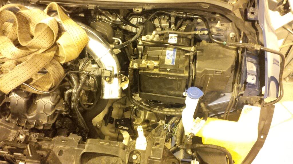
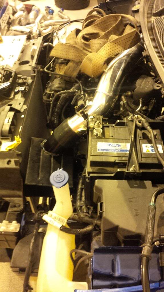
Luckily there's enough on the pipes that we can cut some material out and give the clearance required for a fan whilst still being able to mount the airbox =]
Its going to get even more mental around there when we mount the ECU and IDM in fairly OEM positions but the room is there we just need to package it correctly.
Other than the wiring which is Wills specialty most of the major headaches are now done other than the shifter cables and even then its just working out how to feed them through without removing the entire dash (the shifter will need a custom mount too but hopefully that's not too much trouble as i have my original shifter base ready to butcher).
Pressing on for having all the remaining pieces that are required on order by the end of the week and then its just a case of getting everything in place how we want it and wire it up ready to go!
I'll keep you posted!