I know there are a few E39 boys on here with big petrol engines so whilst converting my 540i Sport to LPG, I took loads of pictures for a write-up on the BMW5 forum, but I feel it would be of interest here too.
Obviously this is what I did and there are a couple of bits I want to tidy up (LPG filter location and coolant hoses) but it is a handy guide if anyone feels they want to crack out the spanners and save themselves a grand on fitting!
First you will need to ensure you have all the bits in your kit to do the install - This ranges from wiring loom, ECU, injectors, various hoses, pipes, clips and the like - Make sure you have it all before you start as it will make the job easier.
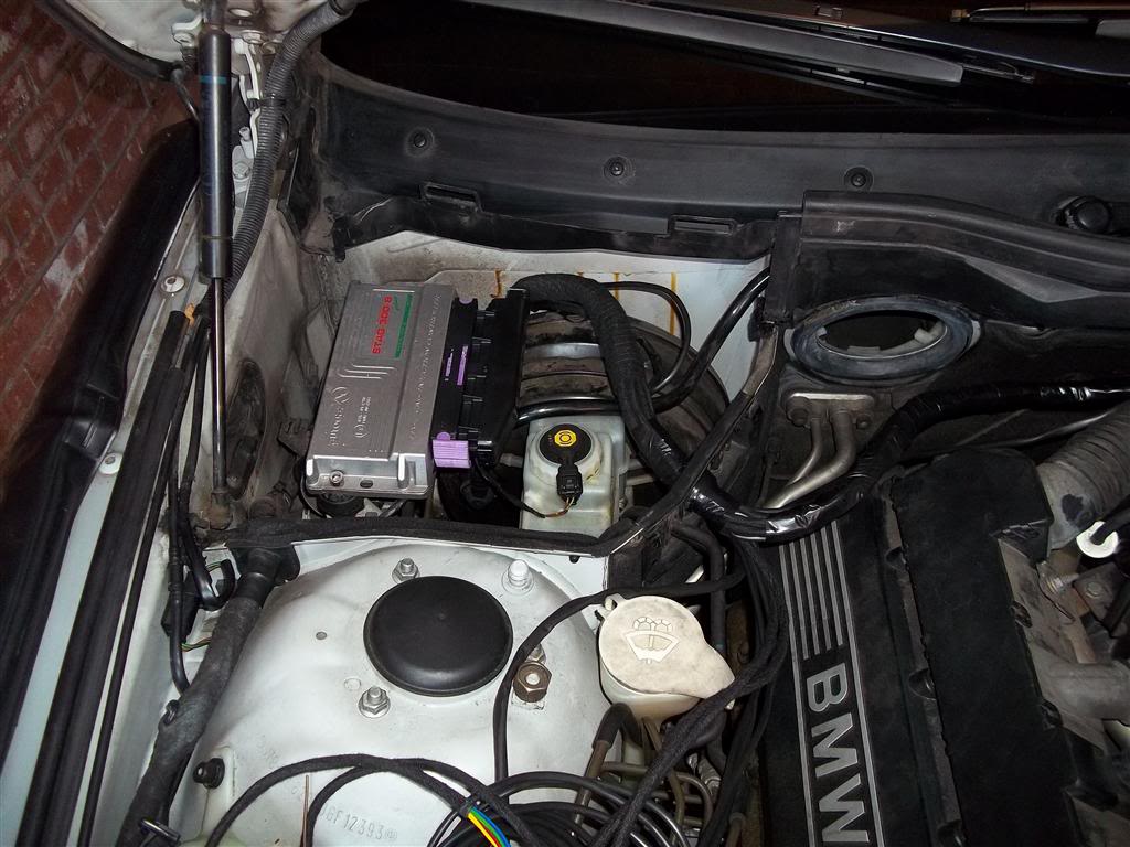
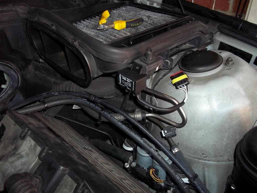
First things first you need to find a suitable location to mount the LPG ECU. I chose under the drivers cabin filter fixed in place using the bolt hole from the OEM brake fluid accumulator - Makes it nice and neat.

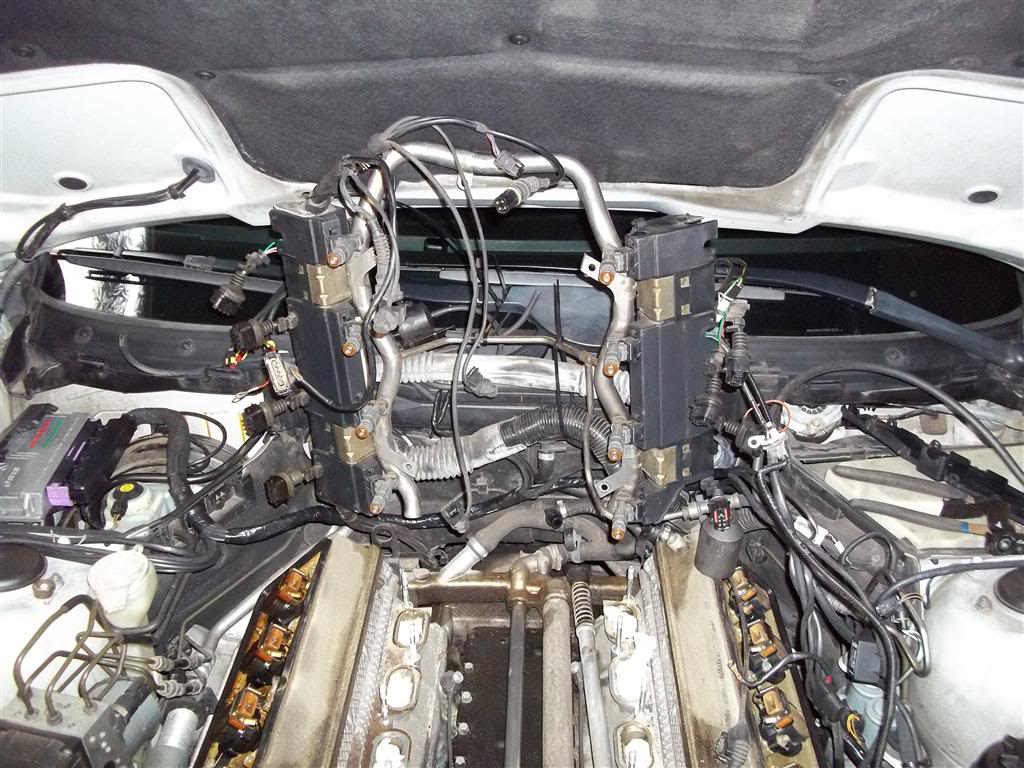
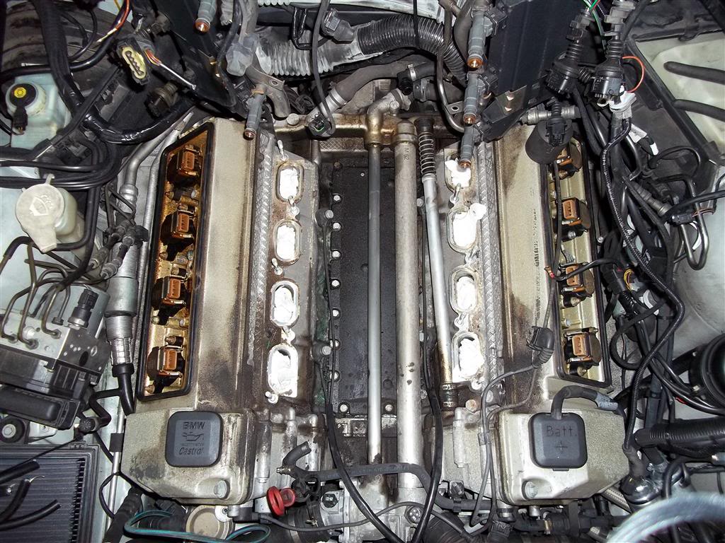
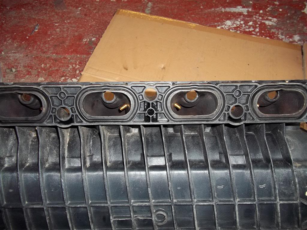
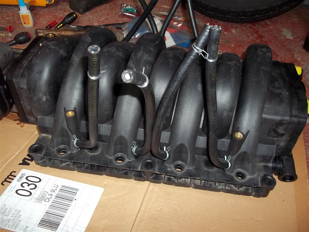
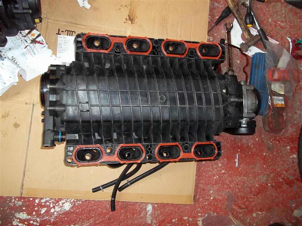
Once you have done this then you will need to remove the inlet manifold so that you can drill the 8 injector nozzle holes required (1 per cylinder) . This is quite tricky to remove due to the fuel rail and wiring boxes already in place. To make the job easy remove the cabin filter intakes on both sides and then unbolt the cover brackets, injector rail and the vacuum accumulator. Also snip off any cable ties holding the loom in place at the rear of the engine - there will be 3 or 4. Once this is done, you will need to unplug all the sensors from the front of the engine in order to remove the wiring loom from there. Remove the coil pack plugs from each coil and also the coil-ground on cylinders 2 and 7. Next remove the AFM and associated pipe-work from the throttle body. When you have done this, gently tug on the injector rail to remove it from the inlet manifold - This will come away with the injectors attached. Push it back up towards the windscreen and secure out of the way. Then unbolt the inlet manifold and give it a gentle prise with a lever to loosen it from the heads. Lift from the rear and front at the same time and then at the rear right, pull off the oil separator pipe from under the inlet manifold. Remove the manifold and then stuff each port with tissue to stop any debris falling down when you clean up the area.
Now we need to drill the inlet manifold for the nozzles. This is very easy and you will need a nice sharp 5mm drill bit and 6x1mm tap. Drill the manifold as close to the injectors as possible to ensure reliability when running on gas. Tap the holes with the 6mm tap and then using locktite studlock secure the nozzles in place. I drilled mine like this to aid the routing of the gas hose and keep the pipes all equal length.
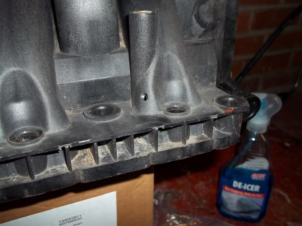
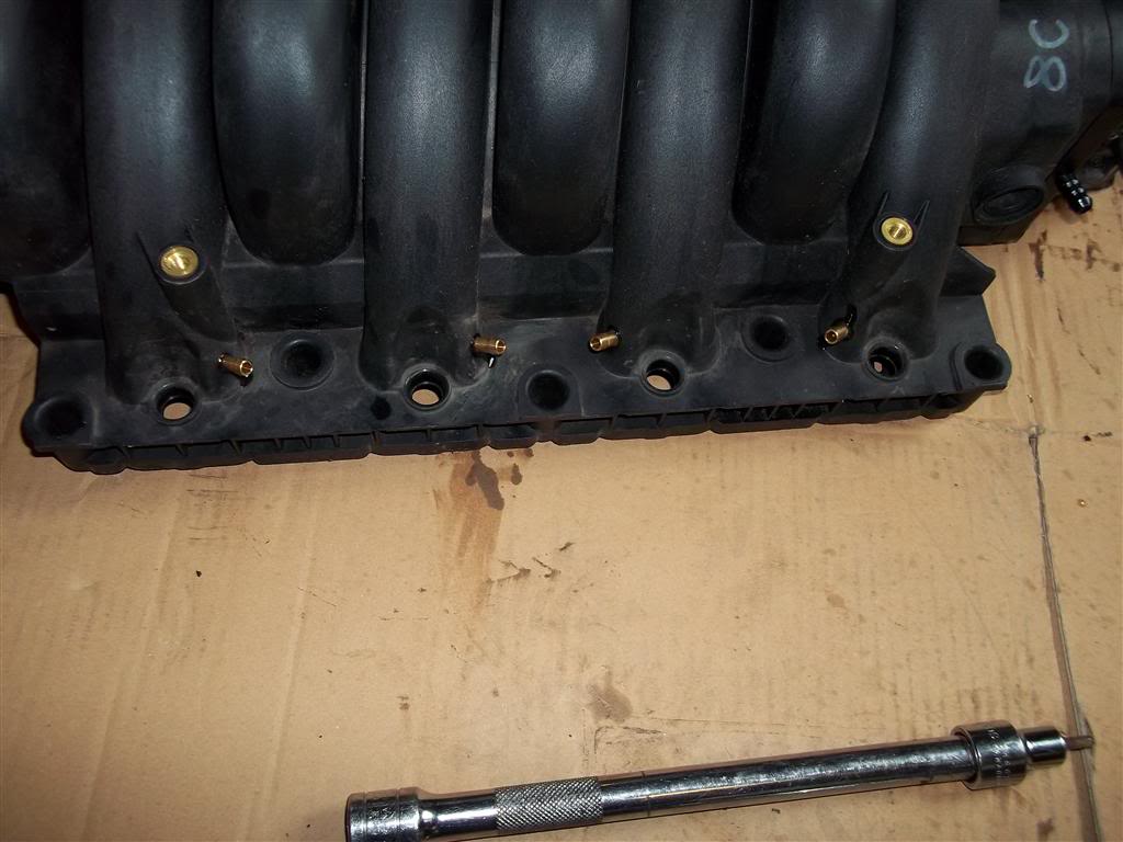
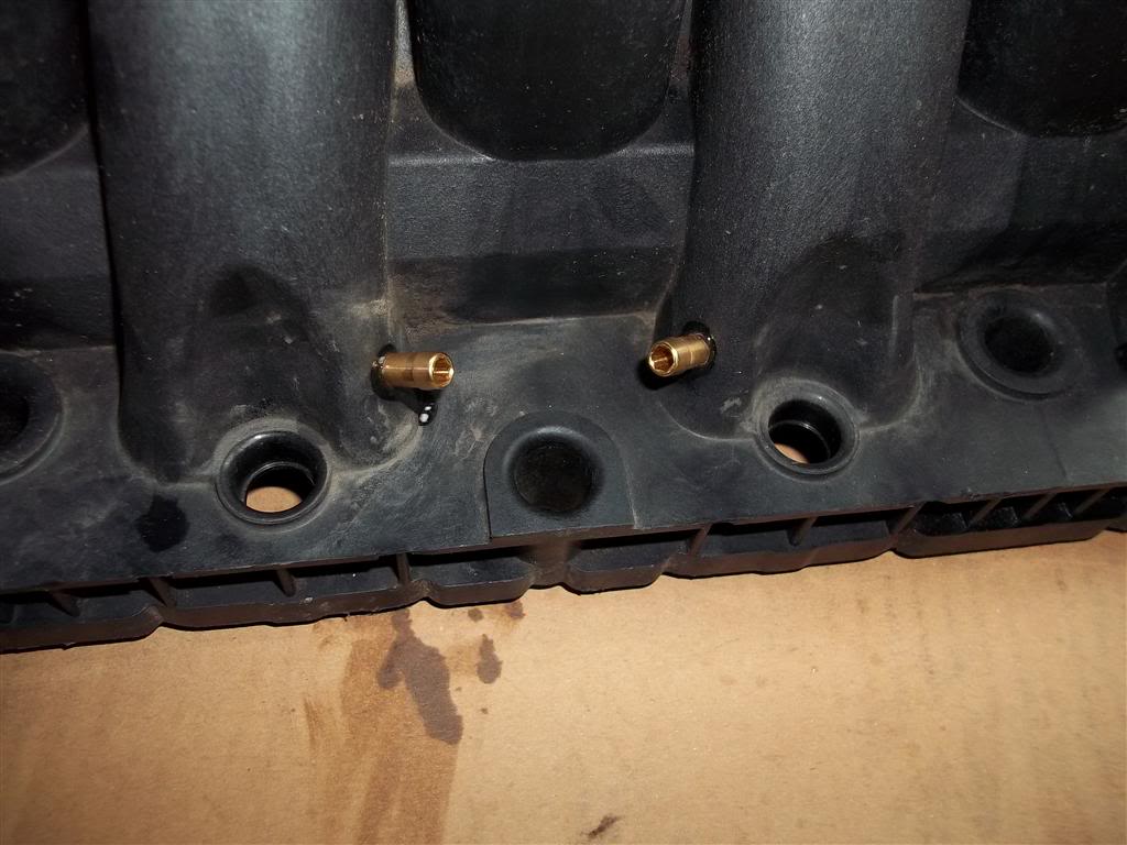
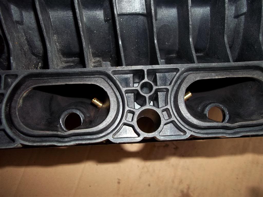
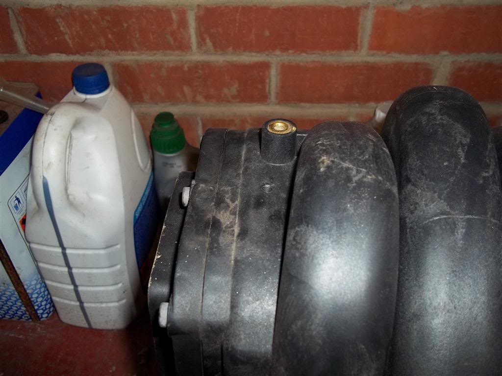
Now drill a 5mm hole in the top of the manifold just behind the fuel rail and tap with M6x1mm tap and secure in the small brass vacuum take-off - this is for the LPG Map Sensor.
Now it is time to fit the pipes to the nozzles. Cut 8 equal lengths of pipe - Ensure you have plenty of spare length on them as you will need to cut them back to size later - Make sure that they are all equal length now as this will save time later when trimming back as you can use a trimmed piece as a guide for how much the others need trimming.
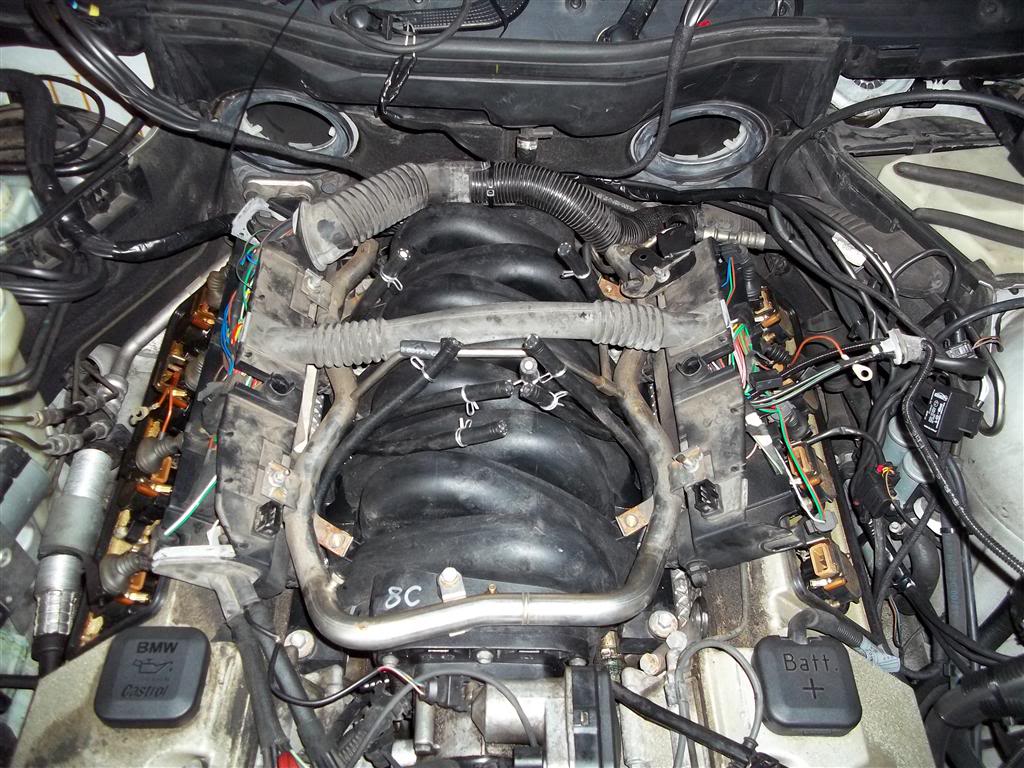
Now fit new manifold gaskets and refit the manifold to the engine and re-connect the injection rail, wiring and anything else you removed.
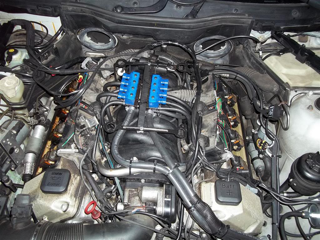
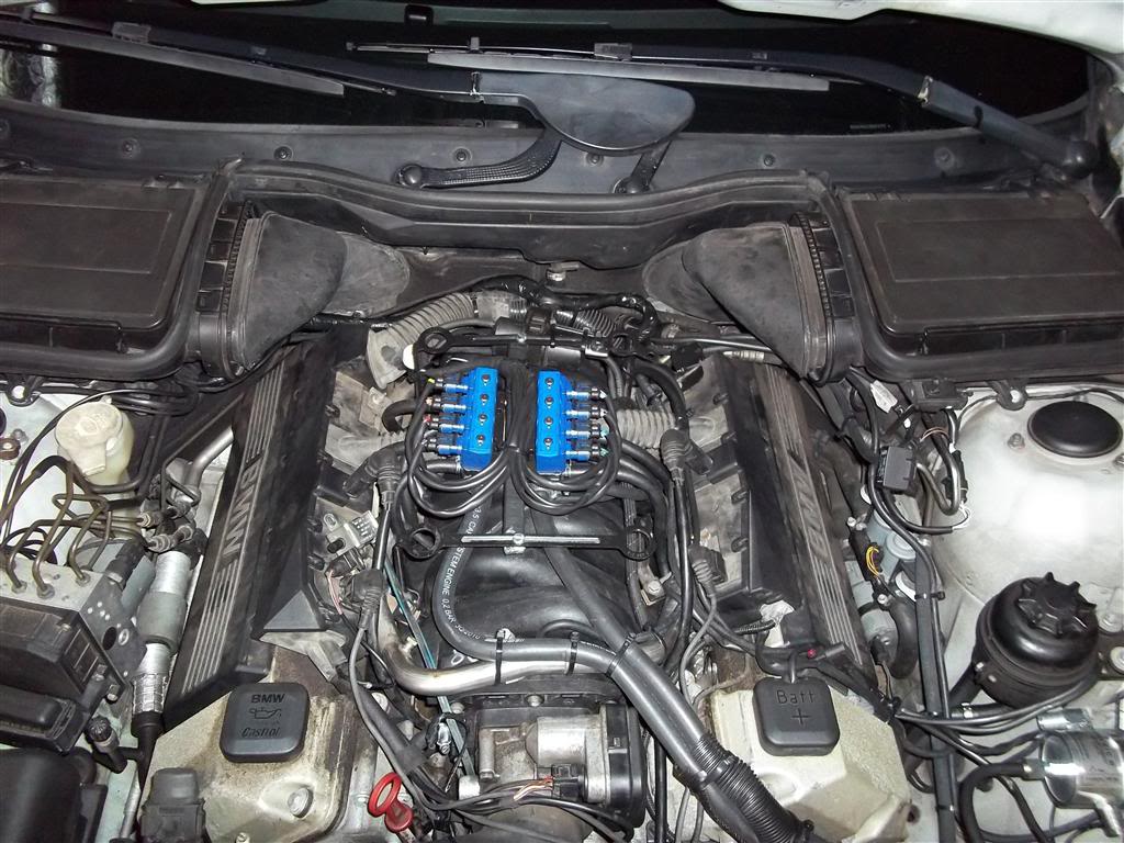
Now it's time to mount the injectors. The OMVL injectors are quite tall and I found choosing a location difficult so ended up with them sat on top of the manifold to give a neat look. I mounted them using a piece of steel bar secured to the cover brackets and secured the injectors via rubber bobbins to the steel bar. You will need to place an M8 nut between the injector rail and cover brackets to space them up by 5mm in order for clearance and to let the cover sit properly once refitted. Now you have mounted the injectors, make sure the pipes are all routed neatly and kink free from the nozzles and connect them to the injectors - If you trim the longest routed pipe first (Cylinders 4 and 8) and then use the piece removed as a guide for how much to trim the other pipes then this will ensure equal length injector pipes for all cylinders - this is imperative for the smooth operation of the LPG system.
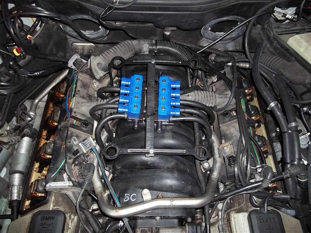
Now we can install the fuel feed to the injectors which will go-to 2 filters and then to the vaporiser. Make sure that these 2 pipes are equal length in their entire run - Once again, imperative to the smooth operation of the kit so do this right. You will see that the left pipe is longer in the run from the inlet manifold to the filters but the pipe on the right is shorter from the filter to the vaporiser - This will ensure equal lengths for both pipes (can you see a pattern forming here?) After doing that, route the vacuum hose from the front of the inlet manifold to the LPG Map sensor and also a positive pressure pipe from the injectors to the LPG Map sensor too. Again ensuring smooth routing with no kinks - Length is no issue here, but obviously the shorter the better.
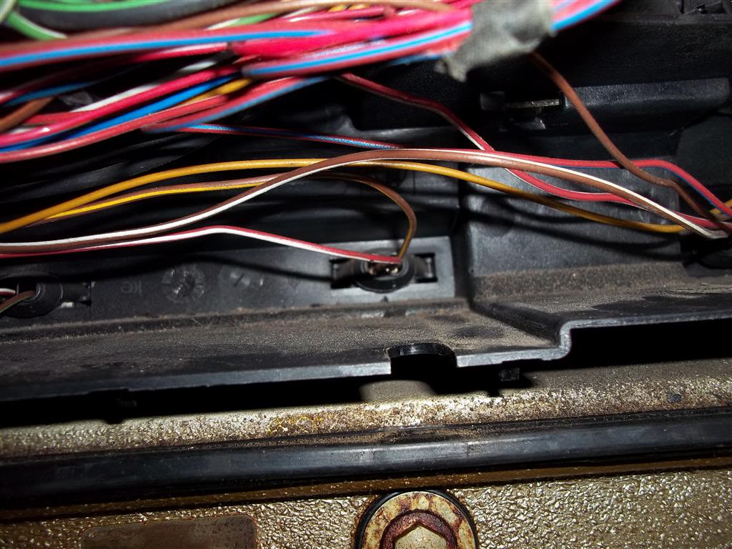
Next up is the wiring loom. This looks VERY daunting but is simple to do - Everything is plug and play apart from a couple of bits. Plug the loom into the ECU and then modify the loom-trap under the cabin filter so the LPG loom can safely and securely pass though and look neat.
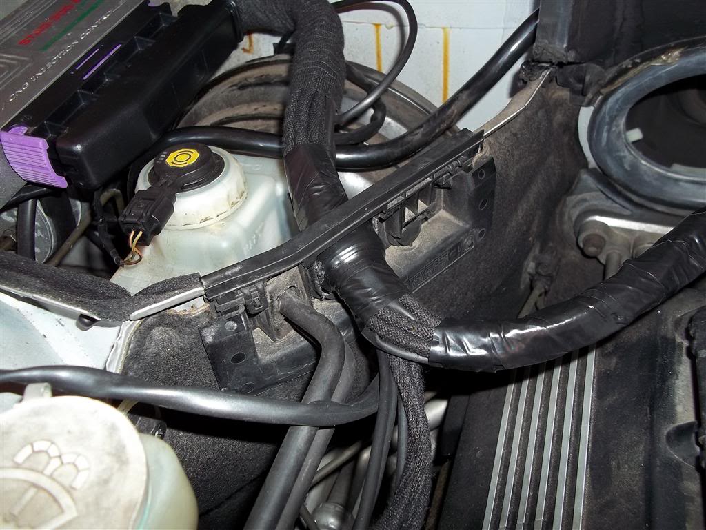

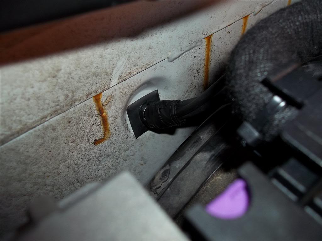
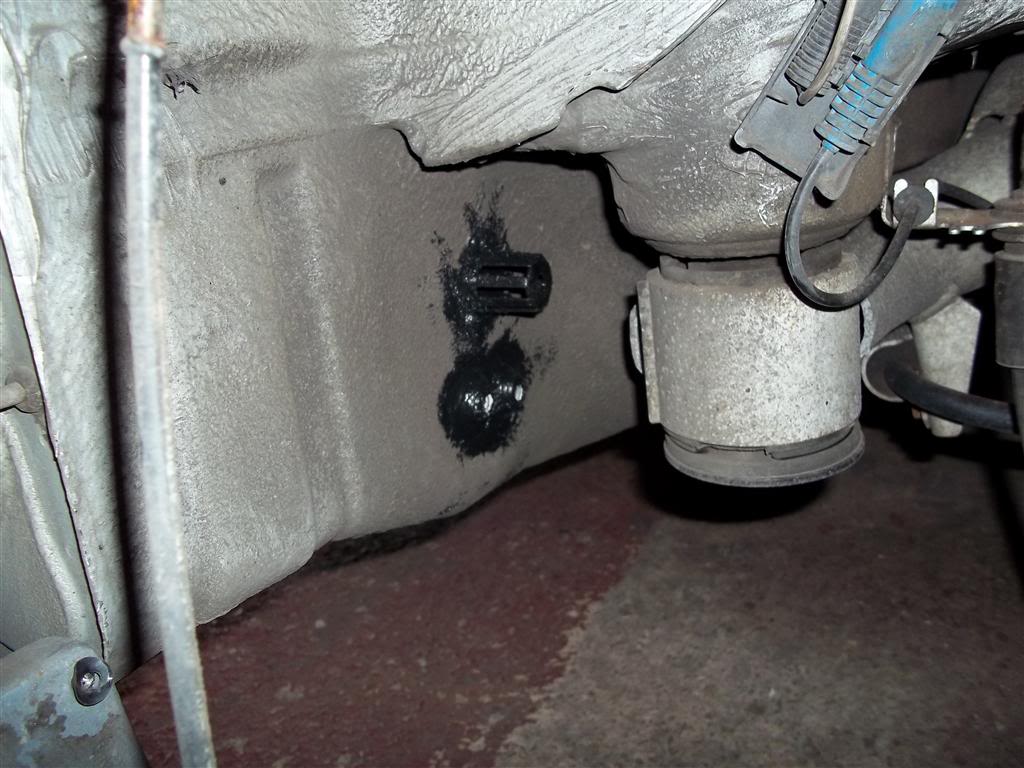
You will need to push some wires into the car (ignition switch feed and dashboard button/gauge wiring) - I used the little square grommet behind the master cylinder and this brings out the wiring above the brake pedal and makes it easy to route under the dashboard.
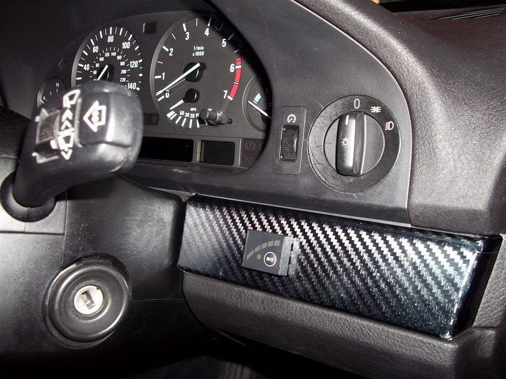
Once the wires are in the car, you need to tap into the ignition switch feed - I did this behind the ignition barrel on the car loom side of the multi-plug (No photo unfortunately) and took about 5 minutes to do. I mounted the LPG switch/gauge on the trim under the headlight switch - This way it is convenient but it won't be easily visible at night to distract you as it will be partially hidden behind the steering wheel and wiper switch column. You will need to solder the wires from the LPG ECU loom to the wires from the switch - Very easy and all colour-coded so no messing here.
Next up is to mount the LPG MAP sensor and route the engine bay LPG ECU loom for the LPG injectors, Map sensor, Shut-off solenoid and vaporiser temperature sensor. This is easy to do and just make sure that everything is safely secure and neat - All these bits are plug and play.
Now you will need to tap into the CAR injector loom in order to splice in the LPG Loom. You can do this either at the ECU or at the injectors - I chose to do it at the injectors as it was easier and neater IMHO.
You will need to locate the ECU switched side of each injector - The wires will be brown with a tracer colour, the red and white wires are switched live and do not need cutting.
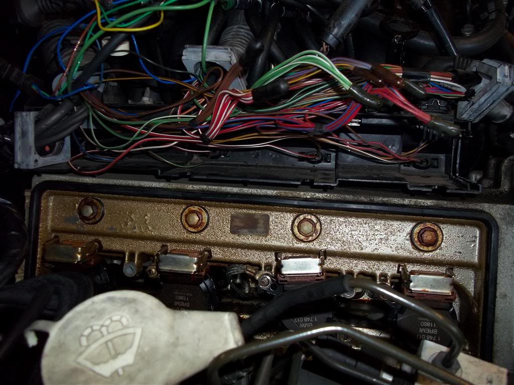
Starting on bank 1, make a hole in the rubber grommet at the back of the wiring cover and push through the wires for cylinders 1-4 and then do the same for bank 2 with the wires for cylinders 5-8. Locate each wire you need to cut from the injectors and then join them with the LPG ECU wiring as detailed in the wiring diagram for the LPG ECU loom. Also you will need to take a signal from the coil pack trigger on number 1 cylinder so do this inside the loom here too.
Once you have done that and ensured everything is soldered properly and heat-shrink protected you can re-assemble the wiring harness covers. You should also tap into the Lambda sensor wiring for each bank (pre-cat sensors) at this time too to save time later. You will need to locate the signal wires from each of the front sensors and connect as per the wiring diagram.
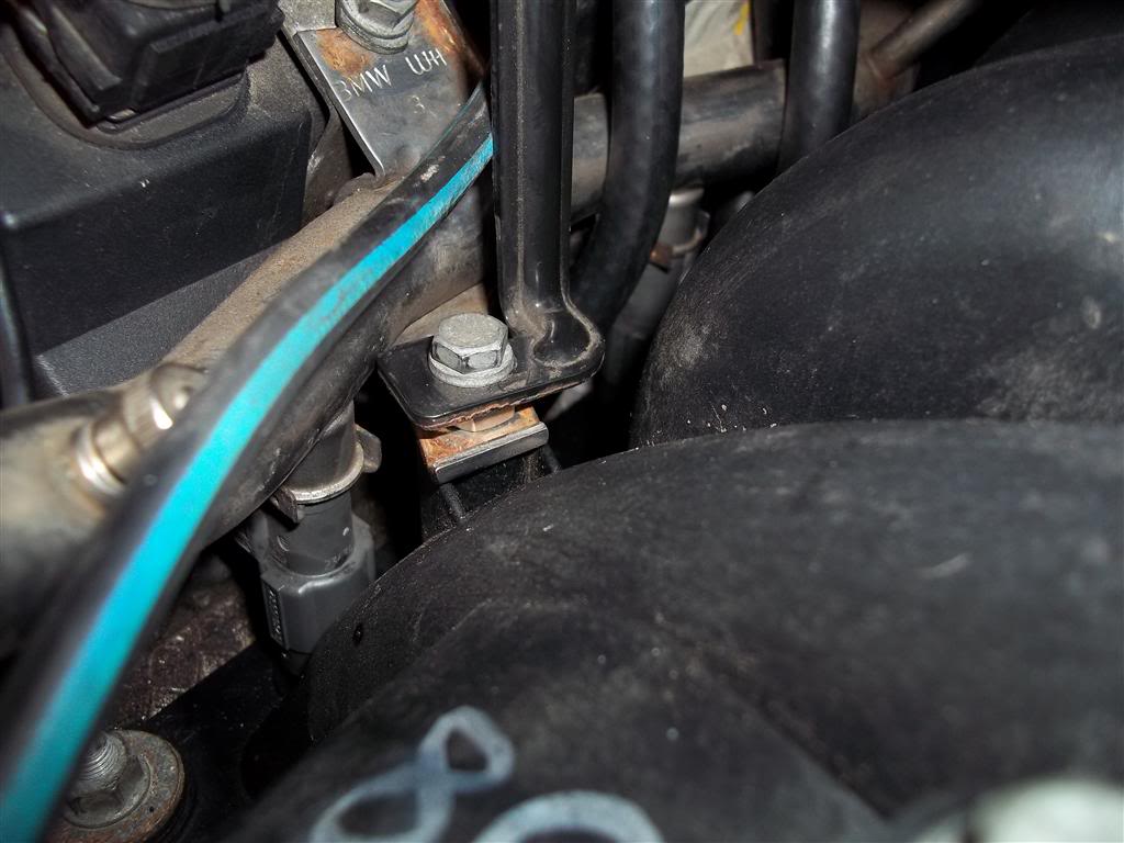
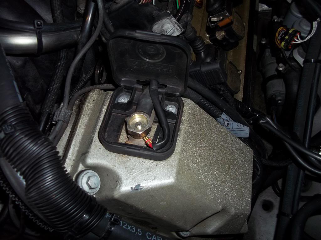
Next up you will need to mount the permanent live for the LPG ECU. I found the ideal place is using the positive jump-start terminal on the engine and having the fuse located just outside of it. The earth can be mounted with the vaporiser bracket.
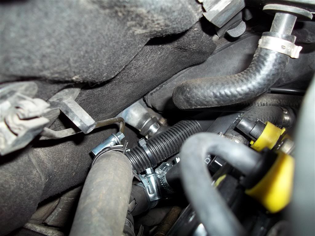
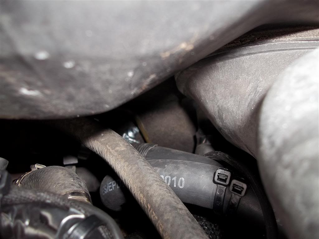
Now it's time to tap into the coolant system and run 2 pipes to the vaporiser - This is daunting as the E39 V8 can be a pain to bleed the coolant system. At the back of the engine is a pipe from the coolant bank to the heater matrix - You will need to tap into this with a T piece and also the pipe that goes to the auxiliary pump on the inner wing with another T piece. This will then allow you to connect the vaporiser in parallel with the heater matrix and this then allows a constant supply of hot coolant to the vaporiser even when the heater matrix stop valves on the inner wing are closed (IE, summer when the air-conditioning is on) This is important as the vaporiser requires coolant to turn the LPG from a liquid to a gas for the system to operate.
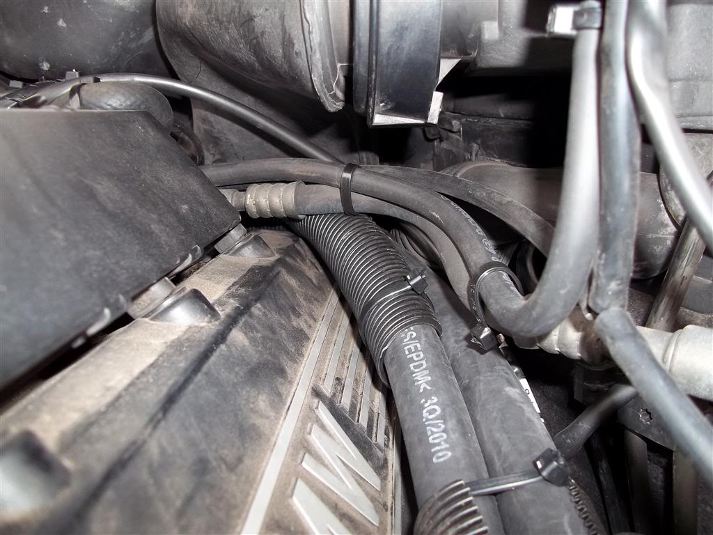
Route the coolant pipes round the passenger side of the engine bay ensuring the highest point is no higher than the top of the radiator so no airlocks will be introduced. I also used some convoluted tube as protection against rubbing - I will change this later to cover the entire coolant run for a neater look.
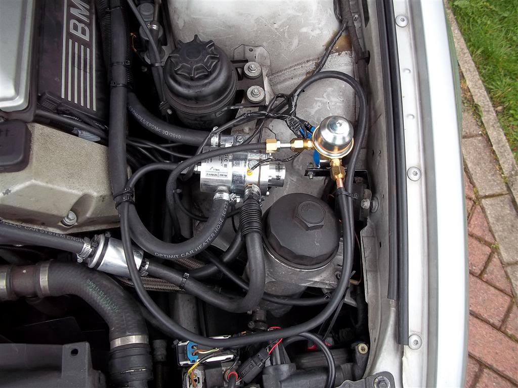
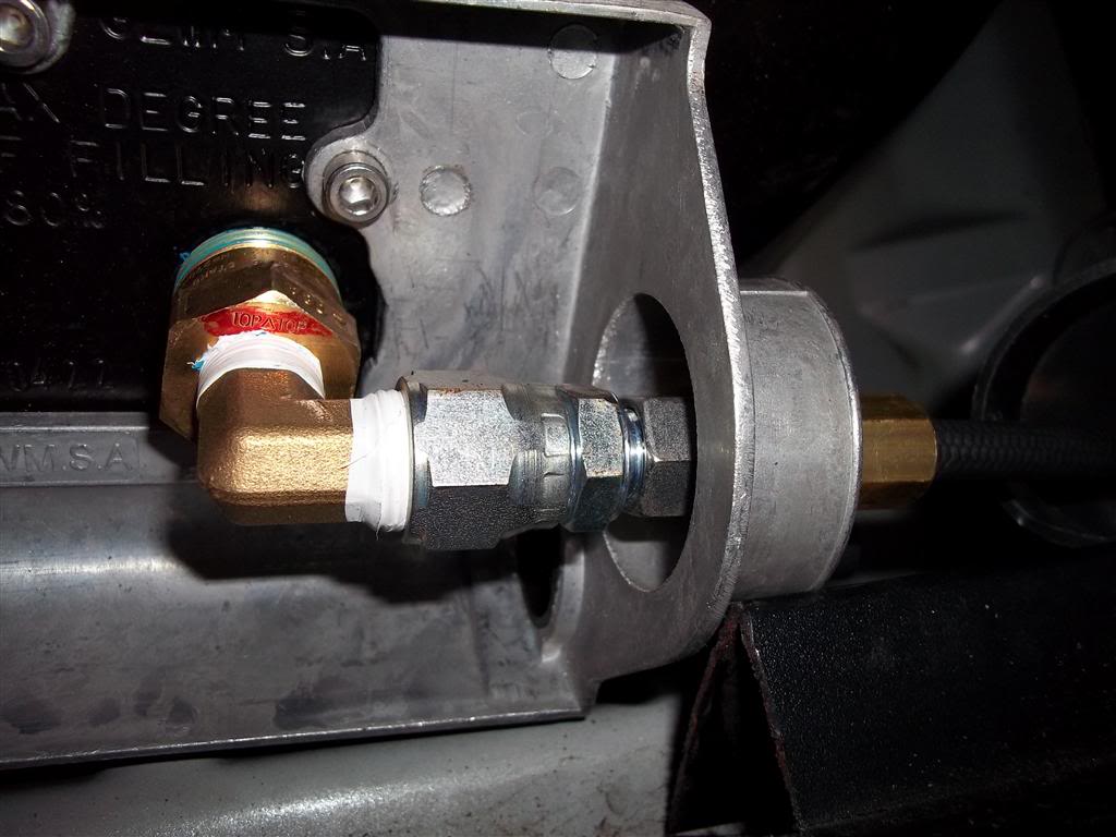
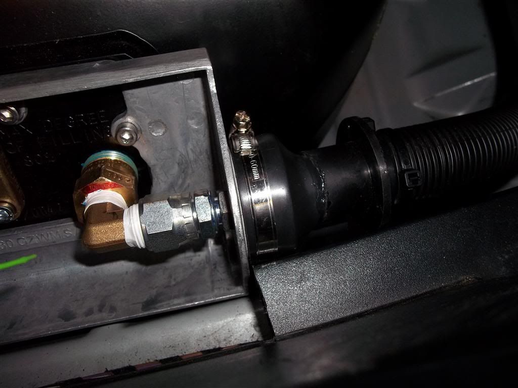
Now you will need to mount the front end gas-stop solenoid and the vaporiser - Very easy to mount and connect them up using the supplied 8mm copper pipe and connect the coolant line from the auxiliary pump first and then back-fill the coolant system through the other pipe before connecting to the vaporiser - This will ensure a minimal introduction of air into the system and will aide bleeding.
Once you have all that done you will need to run the LPG fuel pipe and a 6 core 1mm Sq cable from the front of the car to the rear. The kit supplied 8mm copper pipe but I opted for 8mm Polyflex (LPG approved flexible pipe) as this is easier to route, virtually kink proof and much neater. Choose the routing under the car carefully to ensure no sharp edges or snagging/rubbing and secure very well. I ran mine under the driver's side of the car under the little rubberised plastic flap that is on the sill and it sits in there very neatly and is invisible and well away from any potential damage from objects in the road and saves on laborious clipping and securing (Unfortunately no pictures as I did this at my workshop and left the camera at home). I ran the pipe from the sill in the void behind the wheel arch liner and secured it in there to the fuel filler neck using cable ties to stop it rubbing on anything.
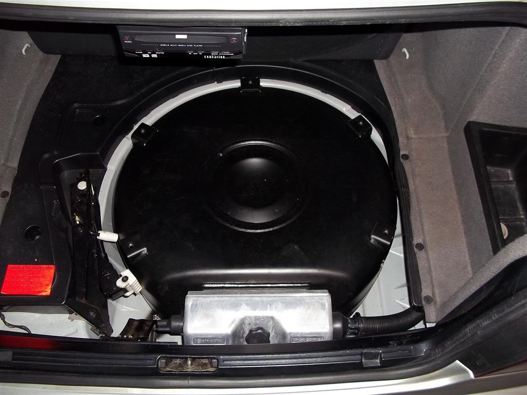
Now the pipe and cable have been run you will need to get them into the boot somehow. I used a pair of IP55 grommets from Screwfix and secured them with sikaflex to stop them coming out and water-tight them. You will need to drill a pair of 20mm holes for these and a 32mm hole for the tank-over pressure vent and LPG fill pipe.
Once you have done this you can mount the tank in the boot and secure using the bolt holes on top of the tank to securing fixtures on the boot floor. I have used a 4 hole spare wheel well tank and this will hold 75 litres of LPG. In order to fit it, I had to cut away some of the plastic boot trim for the tank cover to sit neatly in - This cannot be seen once the carpet is down.
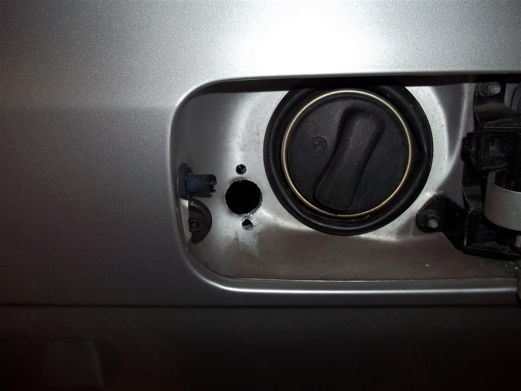
Next up is the filler nozzle - The kit supplied a choice of 2 different filler types, a 70mm circular "traditional" mount that you drill a 70mm hole in your bodywork (no thanks!!!!) or a tow-bar mount. Since I didn't want either of these designs, I searched for an alternative and found a super discreet fitting that goes inside the fuel filler flap area and makes the idea that the car is on LPG invisible to external views.
Easy to fit - Drill a 22mm hole and then place the filler in, mark up for the securing bolts and drill with 6mm hole.
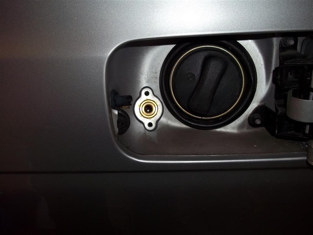
Place plenty of sikaflex around the hole and cover any exposed bare metal liberally and then push in the filler nozzle with the Polyflex 8mm flexible pipe attached and then secure in place

And with the bayonet fitting screwed in for filling up (you can also use all the European connectors with this filler nozzle too, just screw in the fitting of your choice)

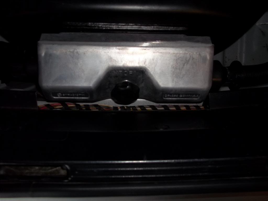
Now connect up the fill pipe to the tank - This will run inside the vent hose from the 32mm hole on the wheel well and when the tank box cover is in place will ensure any gas escaping from the buckholts device (over-pressure) will be vented to atmosphere and NOT inside your car! Ensure you use PTFE tape to ensure all connections are gas-tight.
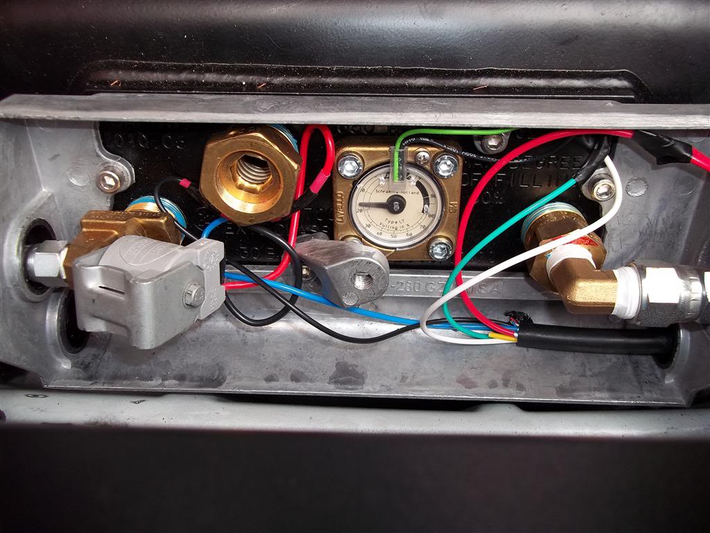
Once that is done, repeat the process for the LPG Fuel Feed line on the other side of the box. Also wire up the stop solenoid and gauge to the cable you ran into the box also - This will need to be connected in the engine bay to the wiring from the ECU and front end stop solenoid so make sure that where possible you use corresponding wire colours in the engine bay to save any confusion at the rear end.
Once all that has been done you will need to bleed the coolant system - Do this by turning the HVAC panel to full temp for both sides and lowest blow setting and then leave the ignition in the run position - this will activate the auxiliary pump in the engine bay and allow you to bleed to coolant system fully.
You will also now need to put some LPG in the tank - Put 20 litres in and this will allow you to ensure there are no leaks in the system and everything is fault free on the plumbing side.
The car will not run on LPG yet until the software has been set up - You can buy a lead and software from the chap who sells the LPG kit and it will be an extra �30.
Take the car for setting up (unless you can use the software yourself to do this) and certification (The chap who sold me the kit includes certification and setting up in the price) and once this is all done you will be free to enjoy the wonders of cheaper fuel.
I anticipate that on an engine of this size, the power loss will be minimal, if any, and the kit will pay for itself within 6 months.
At the time of writing, the LPG kit was �814 (�844 with software/cable) for the complete 6/8 cylinder kit from Simon at
http://www.lpgc.co.uk This price includes full technical support when fitting, full certification and calibration. I am no way affiliated with the company at all, I only used them as a source for the kit as they were local to me in Wakefield.
Fitting to a 6 cylinder BMW would be the same principle for everything apart from the Inlet manifold removal and tapping into the wiring would obviously be different, everything else would be pretty similar.
I had the system fully certified set up today by Simon (He is an LPGA Approved installer/supplier) and it is absolutely superb with no fault lights showing on the dashboard and the engine pulls with all the power of petrol.
The only noticeable difference is the fact the petrol gauge stays still when hoofing it about!