Hi all,
After my experience in trying to get a digital pulsed speed output for a 2WD Cossie for my Blitz Boost Controller, I thought I would post the details so that all may benefit that may need it!
One brief initial warning - before getting involved with this, make sure that whatever you are using with the sensor output can be adequately calibrated! Otherwise, you may be wasting your time.
Background
For information, the L1 - 6 2WD Cosworth ECU's do not have a speed output. Many new gismos these days (from timers to boost controllers etc) require a pulsed vehicle speed sensor in order to operate fully. Modern cars such as the Subaru all take their speedo input from the ECU, and this is who they target their gadgets at! All is not lost however, as all ABS equipped cars are fitted with no less than four speed sensors. All you need to know is which wire to splice into!
Preparation
Firstly, make sure that your current wiring is in good condition. Providing the ABS fault light is not on, there is a good chance that the system is fully operational.
Make sure that you have all the necessary tools to do the job properly, if you leave exposed signal wire, dont come crying if it earths on something and screws either the sensor or the ABS brain.
ABS Brain Location
The ABS control ECU in the 2WD Cosworth is located above the main ECU in the top half of the passenger side of the dashboard, behind the infill panel. The easiest and safesty way to access it is to remove the main ECU and carefully set aside, and then remove the wiring loom harness from the ABS module. Trust me, this will give you more room to work!
Disassembly and wire connection
1) The wiring loom plug to the ABS is normally identified by a Green casing. First, remove the small rubber cover at one end of the plug, and then the outer plastic top will slide back. Keep an eye for two small black plastic infill pieces, which will almost certainly fall out!
2) Once you have exposed the wiring in the back of the plug, you will be able to see numbering adjacent to each of the wires. We are only interested in one of four of those wires.
3) Each Sensor is attached to the Module essentially by two wires - a signal wire, and a shield (earth) wire. For the connection to the speed pulse, we are only interested in the signal wire. DO NOT EARTH THE DEVICE THROUGH THE SHIELD WIRE. Likewise, dont take your main power pickup from this loom. Provide a separate power an earth to whatever you are connecting direct to battery or fuse box!
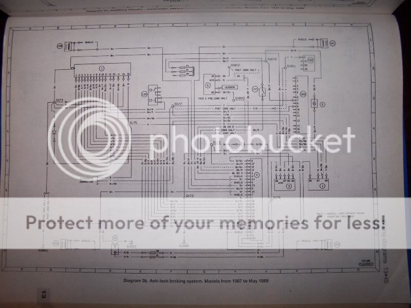
4)Because it is a Ford, the signal from each of the four wheels is helpfully exactly the same colour! (Green). This means that the only way to identify the right wheel is with the assistance of a schematic drawing (attached below)
5) The following represents identification of which wire does what....
Loom Pin no - Wheel - Sensor ID on Schematic
25 - Left Front - 158
22 - Left Rear - 159
23 - Right Front - 160
24 - Right Rear - 161
All of the above are the signal wires, and all are helpfully Green!
6) Free piece of advice! Unless you are wiring to something that directly controls fuelling, wire up to the front wheel. This will ensure that any wheel speed is not affected by wheel-spin!
7) By far the best way to splice into the cable is to trace it back a suitably distance away from the module, and crimp on using an appropriate adaptor. Make sure any exposed wiring is suitably shielded.
8) Once connected, carefully put everything back together.
Calibration
I HAVE ABSOLUTELY NO IDEA HOW MANY TEETH THERE ARE ON ONE OF THE WHEELS! Nor do intend to count them this side of death!
If you need to know, the easiest wheel to check is the front, and to be honest, the best time to do this is whilst changing a wheel bearing, as the abs wheel can be removed from the hub, and then you can count properly on a bench.
The Blitz Boost Controller allows you to self-calibrate, which requires you to drive at a pre-defined speed (25mph) and then press a button. Personally I believe that this is best done on the open road with a GPS. Most speedos have an inherant inaccuracy. If you are using devices that provide estimates of BHP, if you time your device to your Speedo, it will almost certainly mean that you are going slower than you thing, and therefore the BHP figures will come back better than they should be! Garbage in - garbage out!
All Done
Hey presto, you now have a proper speed output for whatever device you require.
I believe that the ABS sensors are used by RaceLogic when installing their traction control system.
The Pictures!
Below is the schematic for the ABS complete system. This is the same for all Sierras up to 1989. Also is the two pages of guidance notes that identify the sensors and modules etc!
They are from a well known brand of car manuals!


I hope that this helps at least one other person!

(Edited photo sizes to smaller)
JJ