Originally Posted by foreigneRS
Originally Posted by BMEP
On the dyno it made an extra 16hp to the wheels. There was no need to remap the ecu.

Originally Posted by BMEP
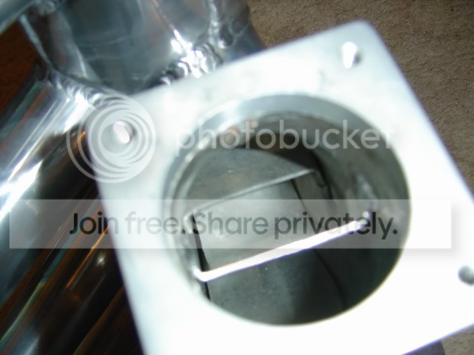
The main idea of the spacer was to increase the distance between the trumpets and the inner wall of the plenum as this is only 10mm.
that's what it actually does, but what is the point of doing that? as i say, it's to give more even air flow to each cylinder.
foreigneRS,
I�m happy to go into detail about the effects that the plenum spacer has so you get a better understanding to how it works mate

. The easiest way to look at the situation is as follows���..
Consider each trumpet within the plenum having an individual throttle body on the end of them. The amount the throttle body is open is determined by the distance between the trumpet and the inner plenum wall. For instance if the plenum wall was butted up against the trumpet this would resemble 0% throttle, when the distance between the trumpet and the plenum wall was at its furthest point this would be seen as 100% throttle.
When a plenum spacer is fitted, the distance from the trumpet face to the inner plenum wall becomes 26mm (10mm + 16mm). This would resemble 100% throttle. If the spacer was removed this distance would now become 10mm and therefore resemble a throttle opening of (say) 80% and reduce power output in the higher rpm range of the engine. NOTE; we all know that cossies don�t have 4 throttle bodies. This is purely a means of explaining the theory.
When you say that the plenum spacer is designed to achieve the following����. �It�s to give even air flow to each cylinder� I totally disagree. Firstly everyone knows that when a cossie piston/s fails at high boost 90% of the time it is piston 3 or 4 that melts. This means that these Cyls are running leaner than Cyls 1 and 2. There are a few reasons to why this can occur BUT it�s obvious that it is due to uneven air distribution due to the elbow location on the stock plenum.
Firstly, when we did dyno testing, we monitored the EGT (Exhaust Gas Temperature) of each Cyl by taking a reading with a laser thermometer on the Exh runners of each Cyl. NOTE; when these readings were taken the engine was cooled by running the workshop hose over the engines radiator and NOT the fan due to the fact that if the fan was cooling the radiator it would also be passing air over the Exh manifold and result in inaccurate figures as the air would pass over runner 1 and pick up heat and pass the heated air towards the rear Cyls.
When the engine was held static at a given load/rpm, Cyl 3 would run 75 Deg C hotter (EGT) than the average temp of Cyl 1 & 2. Cyl 4 would run 60 Deg hotter (EGT) than the average of Cyls 1 & 2.
I considered the fact that the engine coolant enters into the engine from the front (Cyl 1) then continues towards the rear of the engine (Cyl 4). There is no doubt this would effect the EGT when comparing Cyl 1 to Cyl 4 however NOT by 75 Deg C (EGT) as there would only be a approx 3-5Deg C temp (water) variation from the front to rear of the engine block.
I also considered the fact that the fuel enters the fuel rail from one side only with the reg on the opposing end and considered the possible oscillation of fuel within the fuel rail due to the engines 1-3-4-2 firing order. To help counter react this I made/fitted a new fuel rail that feeds fuel into the rail from both ends and has the return to the fuel reg in the centre of the fuel rail. (In fact I still have this fuel rail on my engine). Back on the dyno and there was no improvement to Cyl 3 & 4. Also, when the injectors were removed to fit the new fuel rail they were individually checked to see if they all flowed the same amount and they did.
Now by fitting a plenum spacer there is no means of increasing the air flow to Cyls 1 & 2 ONLY without affecting the air flow to Cyl�s 3 & 4 hence indicating that the plenum spacer is not effective in your claimed ��.�it�s to give even air flow to each cylinder� as you keep referring to. It is obvious that the irregular air distribution of the stock intake manifold is due to the positioning of the stock elbow.
The methods to achieve even air distribution to each Cyl would be by fitting �air deflector� plates within the elbow/plenum as I have on my custom made plenum.
When the plenum spacer plate was fitted/tested on the dyno we did not re map the ecu and had no problems what so ever. In fact the change in the air/fuel of the engine was negligible and I believe there would be very little if any gain in re mapping the fuel map and I seriously doubt there would be the need to alter the ignition map.
Another method to help this situation of uneven air/fuel ratios between Cyls would be via an after market ECU such as an Autronic as this ECU can trim each injector/Cyl individually to help balance the air/fuel ratio within each Cyl BUT not even out air flow to each Cyl. In this case you would be tuning each Cyl as a separate engine rather than a single engine.
When you think about it, it is commonly taken for granted that when a 3� big bore Exh system is fitted/removing the cat or removing the stock air box and replacing it with a pod filter or by fitting an RS500 intercooler that there is no need to re map the ecu. Id say that the performance increase of these item would be similar (but not exactly the same) as the plenum spacer and yet people fit these items without the need to a re mapped of the ecu.
After saying all this I am interested in your theory to how/why the plenum spacer can �give even air flow to each cylinder� For interests sake I would appreciate a �detailed� reply rather than a simple single sentence answer
