

I have decided that i want to see how crazy i can go and design a carbon chassis.
It will be based dimensionally around the wheelbase and rough dimensions of the puma but the body panels themselves will in essence be cosmetic/weatherproofing only.
This is not going to be a quick project so if youre hoping to see a carbon chassis built in the next few months then look elsewhere
Initially its a design exercise, mostly in solidworks CAD along with some destructive testing of representative test panels etc to refine the design and structural strength as required.
Hopefully if it works out feasable then i will build the chassis and as a full car. I already own over 100 square meters of carbon, most of the core material i need. The rest i can source through work at cost price so in terms of affordability, a simple monococque chassis isnt as expensive as you might think in material costs.
Firstly i need to re-learn CAD. Its all changed since i did it back in 1999/2000 and moved from being programmed by hand to being based on mouse commands and a simple menu interface. Should be able to learn it fairly quickly and much quicker than it took me to learn C and program in linux k-shell.........
A few fixed constraints,
Must fit within puma profile
same wheelbase as current puma.
Will be engineered for cossie drivetrain
ability to add steel roll cage if full roof and roll over protection not already built into design.
Im still in split minds about using cossie based suspension set up or going the full hog and designing a double wishbone set up front and rear. Have some suspension design reading to do over the next few months and a fair few calculations to work out what is the best way forward.
Few initial rough sketches based on cossie subframes and beam:
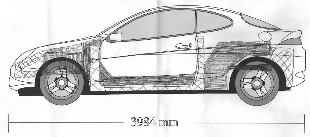
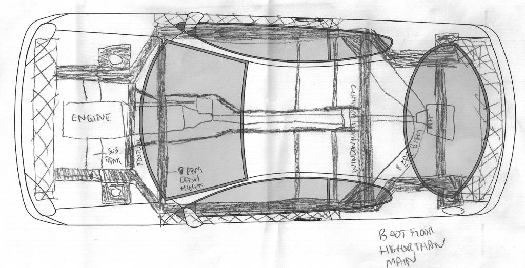
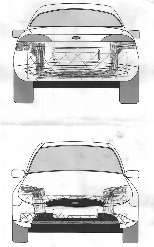
Will be a lot of work to get anywhere near a functioning design but will get there eventually.
It will be based dimensionally around the wheelbase and rough dimensions of the puma but the body panels themselves will in essence be cosmetic/weatherproofing only.
This is not going to be a quick project so if youre hoping to see a carbon chassis built in the next few months then look elsewhere
Initially its a design exercise, mostly in solidworks CAD along with some destructive testing of representative test panels etc to refine the design and structural strength as required.
Hopefully if it works out feasable then i will build the chassis and as a full car. I already own over 100 square meters of carbon, most of the core material i need. The rest i can source through work at cost price so in terms of affordability, a simple monococque chassis isnt as expensive as you might think in material costs.
Firstly i need to re-learn CAD. Its all changed since i did it back in 1999/2000 and moved from being programmed by hand to being based on mouse commands and a simple menu interface. Should be able to learn it fairly quickly and much quicker than it took me to learn C and program in linux k-shell.........
A few fixed constraints,
Must fit within puma profile
same wheelbase as current puma.
Will be engineered for cossie drivetrain
ability to add steel roll cage if full roof and roll over protection not already built into design.
Im still in split minds about using cossie based suspension set up or going the full hog and designing a double wishbone set up front and rear. Have some suspension design reading to do over the next few months and a fair few calculations to work out what is the best way forward.
Few initial rough sketches based on cossie subframes and beam:
Will be a lot of work to get anywhere near a functioning design but will get there eventually.
Glenn_
Glennvestite
close


May 13, 2026
- Join DateJul 2006
- LocationDarlington county durham
- Posts:62,772
-
iTrader Positive Feedback100
-
iTrader Feedback Score(1)
-
Likes:168
-
Liked:1,050 Times in 1,003 Posts
Will be cool if you can do this Warren.

PassionFord Regular
cool project even from a design point, but unless your constructing your chassis from a singular piece of carbon no joints or bonds it will be next to impossible to gain realistic stress simulations also finding out the material specifications of your grade of carbon and resins the technique to fuse them, i would of thought to gain the material specifications needed to calculate stress's will involve a fair few destruction tests with load measuring equipment. if you want once you have a CAD model knocked up i can test it in CFD software to find possible aerodynamic improvements in design.



Regular Contributor
Looking forward to lurking on this. Did you ever see that guy on driftworks that built carbon cars including a Ferrari? Really interesting!
Jordan
Jordan

PassionFord Post Whore!!
Great idea but if you're going to that trouble I'd use something a lot better than a shitty Sierra rear beam!

Looks like a grand project you have on the go here Warren
Quote:
To be fair you can construct individual parts into assemblies in the CAD im using (solidworks) including then joining the assemblies/parts together using bonding or other techniques. Originally Posted by fezzielove
cool project even from a design point, but unless your constructing your chassis from a singular piece of carbon no joints or bonds it will be next to impossible to gain realistic stress simulations also finding out the material specifications of your grade of carbon and resins the technique to fuse them, i would of thought to gain the material specifications needed to calculate stress's will involve a fair few destruction tests with load measuring equipment. if you want once you have a CAD model knocked up i can test it in CFD software to find possible aerodynamic improvements in design.
As standard it has material properties databases for much of the basic materials i would use, plus i can download more specific composites data and what i cant find i can add in myself using the technical specifications i have for the products i want to use.
Sure CAD is never as good as real life as CAD assumes everything is pretty much perfect but you can engineer in tolerances to take into account variations in practical bond stength and the real world practical methods of joining carbon panels.
Plus testing sample panels is a perfectly valid way of getting representative real world data.
Quote:
it was just on the outline sketch i downloaded Originally Posted by Maxwell
3 spokes on a puma
Quote:
As said id probably end up with something more fancy long term but as a design exercise i want to keep it simple to start with and use known reference points. Once its all referenced, its dead easy to change anyway as you just create various datum points in your 3D image and work from those.Originally Posted by XRT_si
Great idea but if you're going to that trouble I'd use something a lot better than a shitty Sierra rear beam!
Probably end up double wishbone. Mounting double wishbone bracketry onto a carbon chassis isnt that bad from the research and examples ive seen. Designing a good double wishbone set up is the hard bit
My reading for the next couple of weeks:
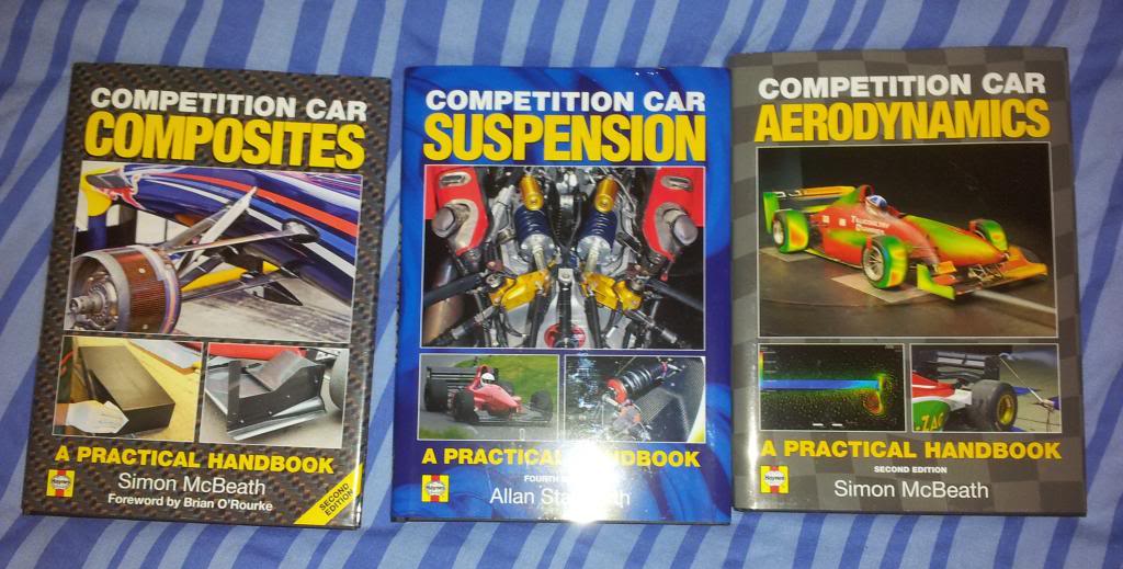
SHould keep me busy while learning Solidworks and make sure i get the basics right.
SHould keep me busy while learning Solidworks and make sure i get the basics right.

cannock is a race track
My uncle is head weaver at a big carbon fibre company, I'm almost certain that it would need to be made from 1 piece. All carbon, bikes, wheels ect are all 1 piece.

yep aware of the gould puma.
Quote:
I doubt you will find any carbon monococques made from a single piece of carbon fibre!! Even formula 1 tubs are made in sections and often have joins.Originally Posted by theburns1
My uncle is head weaver at a big carbon fibre company, I'm almost certain that it would need to be made from 1 piece. All carbon, bikes, wheels ect are all 1 piece.
PassionFord Post Whore!!
very cool project if you go for it, but all that effort to then use a sierra beam and puma body seems sad 

SLOW LEARNER
Rather than design a new double wish bone setup would it not be easier to borrow one from another car, noble M12 seems a logical choice as they are compatible with ford parts? Just a thought
Im looking at all options. If i can find a set up i can fit within the dimensions i need and they will sell me the bits, then that might be far easier.


I love fast Puma's Mike Mannings Puma and Mike Endean Gould Puma are both awesome machines:
Rich
Rich

Advanced PassionFord User
Will be an interesting project to watch develop. One thing that caught my mind was mention of using a steel cage. I'd be inclined to build a roll over hoop into the carbon chassis to keep the CoM lower.
Its mostly only single seaters that have full carbon roll over protection and it has to be heavily crash tested to meet FIA rules.
However with the correct load spreading plates, a bolt in roll cage is perfectly ok. Plenty of the supercar type cars with monococque chassis have bolt in cages for GT series and the like.
Done a bit of research and a lot of monococque tubs are using a fairly simple skin based around either a 10mm foam core panel or 10mm honeycomb increasing to 15mm in some areas. Obciously the higher the level of motorsport, generally the more technical the core - ie slightly stiffer but lighter yet twice the cost!!
Some of the bigger sports cars use double skins formed into a box type section.
Also in a lot of the carbon cars they make use of honeycomb to form crash structures for frontal impact.
So with a bit of discussion with work colleagues ive come up with a sketch of my sill structure:
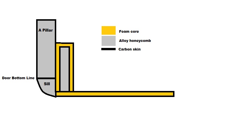
The outersill is original body panels remade in carbon with the void filled with honeycomb as a crash structure. It is not part of the monococque but represents the bodywork and in effect a replacement crash structure for minor accidents.
Ive chosen to use foam core. Its cheaper than alloy honeycomb and easier to produce a consistant strong panel (consistancy is important when you consider how much panel i will need!) and the only penalty being a 20% weight increase over honeycomb cores.
Plus its much easier and cheaper to make. The core isnt massively more expensive if you use honeycomb, however the specialist glue film sheeting, which needs oven curing, IS expensive and could easily add a couple of grand to the cost of a monococque.
I also intend to fill the monococque side panel voiding with honeycomb. It will add some stiffness plus add further crash protection with the honeycomb absorbing energy as it crushes.
Should give me a good strong side profile.
However with the correct load spreading plates, a bolt in roll cage is perfectly ok. Plenty of the supercar type cars with monococque chassis have bolt in cages for GT series and the like.
Done a bit of research and a lot of monococque tubs are using a fairly simple skin based around either a 10mm foam core panel or 10mm honeycomb increasing to 15mm in some areas. Obciously the higher the level of motorsport, generally the more technical the core - ie slightly stiffer but lighter yet twice the cost!!
Some of the bigger sports cars use double skins formed into a box type section.
Also in a lot of the carbon cars they make use of honeycomb to form crash structures for frontal impact.
So with a bit of discussion with work colleagues ive come up with a sketch of my sill structure:
The outersill is original body panels remade in carbon with the void filled with honeycomb as a crash structure. It is not part of the monococque but represents the bodywork and in effect a replacement crash structure for minor accidents.
Ive chosen to use foam core. Its cheaper than alloy honeycomb and easier to produce a consistant strong panel (consistancy is important when you consider how much panel i will need!) and the only penalty being a 20% weight increase over honeycomb cores.
Plus its much easier and cheaper to make. The core isnt massively more expensive if you use honeycomb, however the specialist glue film sheeting, which needs oven curing, IS expensive and could easily add a couple of grand to the cost of a monococque.
I also intend to fill the monococque side panel voiding with honeycomb. It will add some stiffness plus add further crash protection with the honeycomb absorbing energy as it crushes.
Should give me a good strong side profile.