Rear wheel drive XR2
 07-12-2013, 07:31 PM
#41

Done some more work to the car. I'll post images up asap, but most of the transmission tunnel ands
front/rear diff covers done. Made progress with steering column and had to change some things. Pleased with progress though.
front/rear diff covers done. Made progress with steering column and had to change some things. Pleased with progress though.


 08-12-2013, 06:53 PM
#43
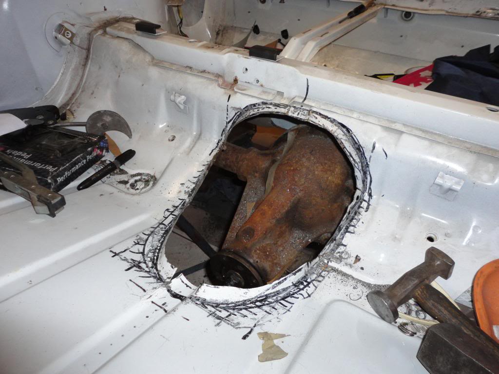
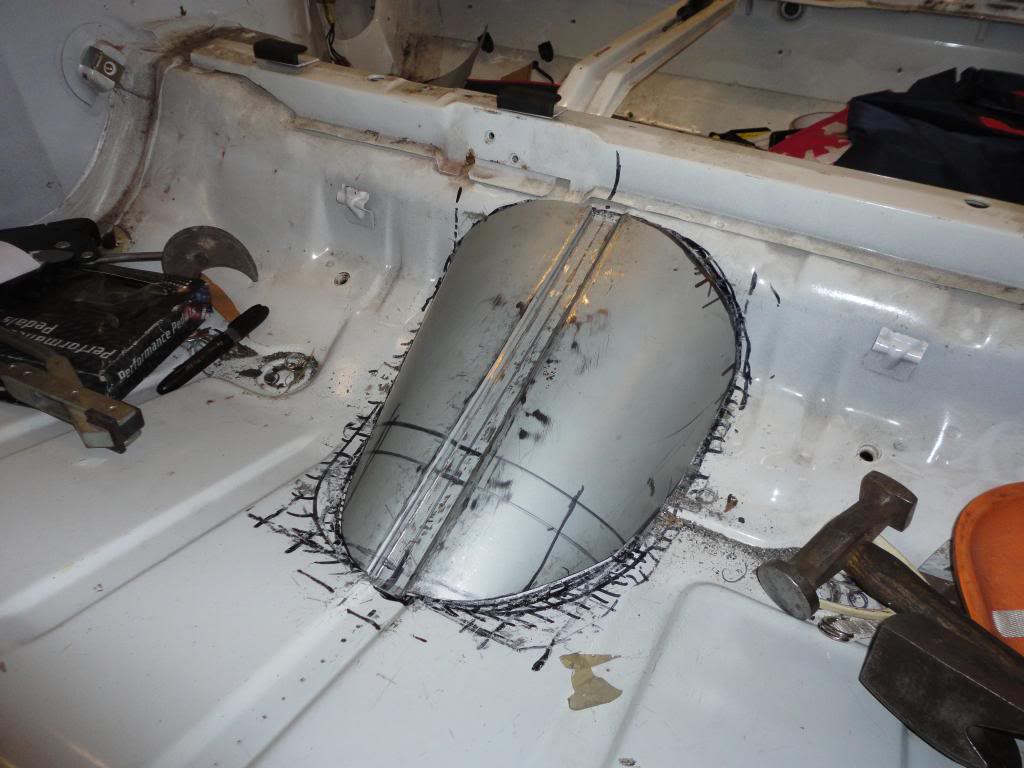
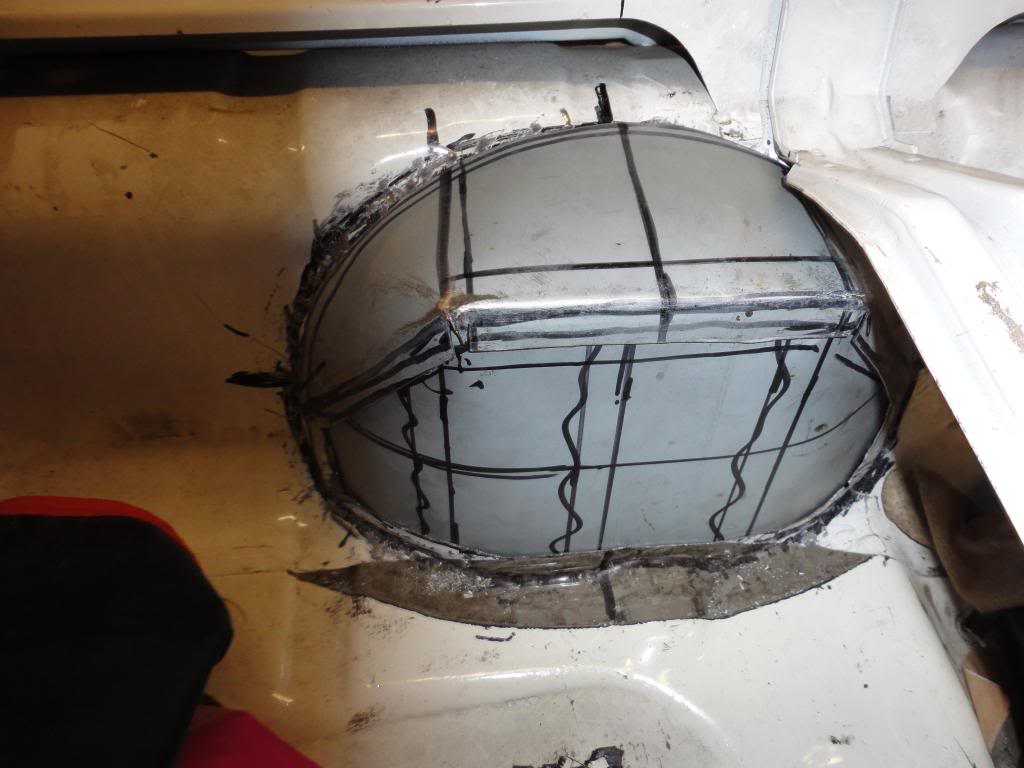
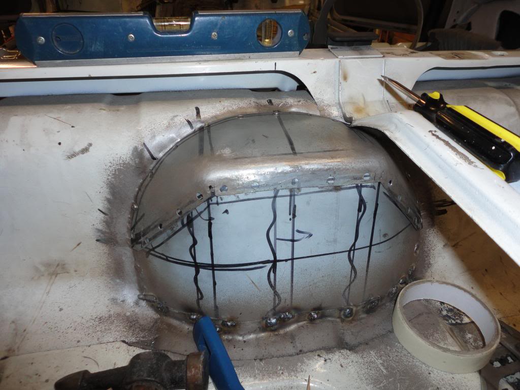
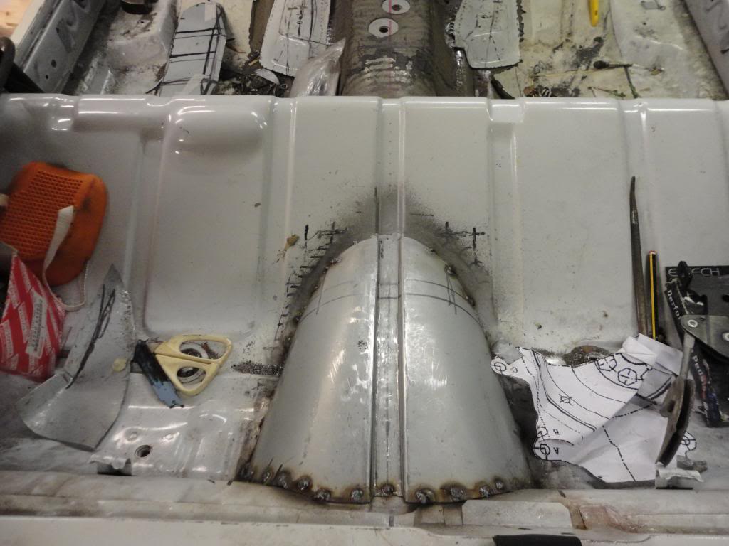
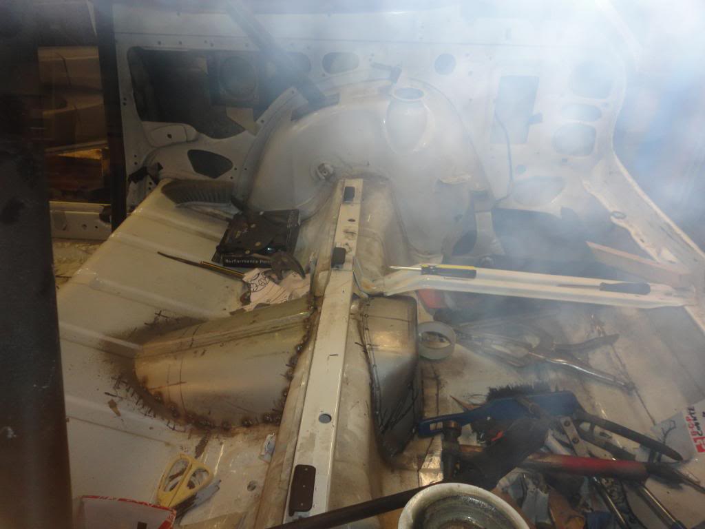
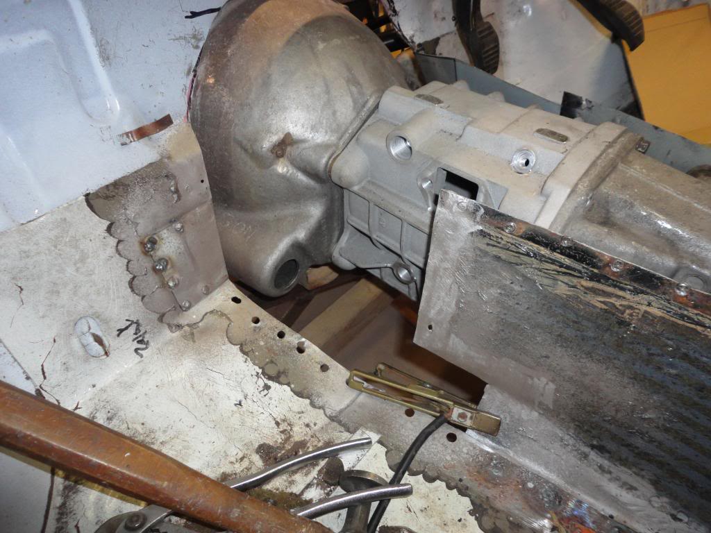
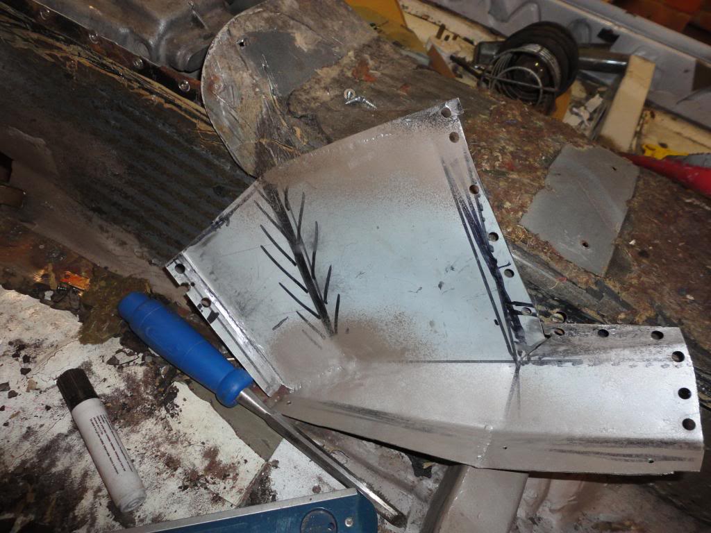
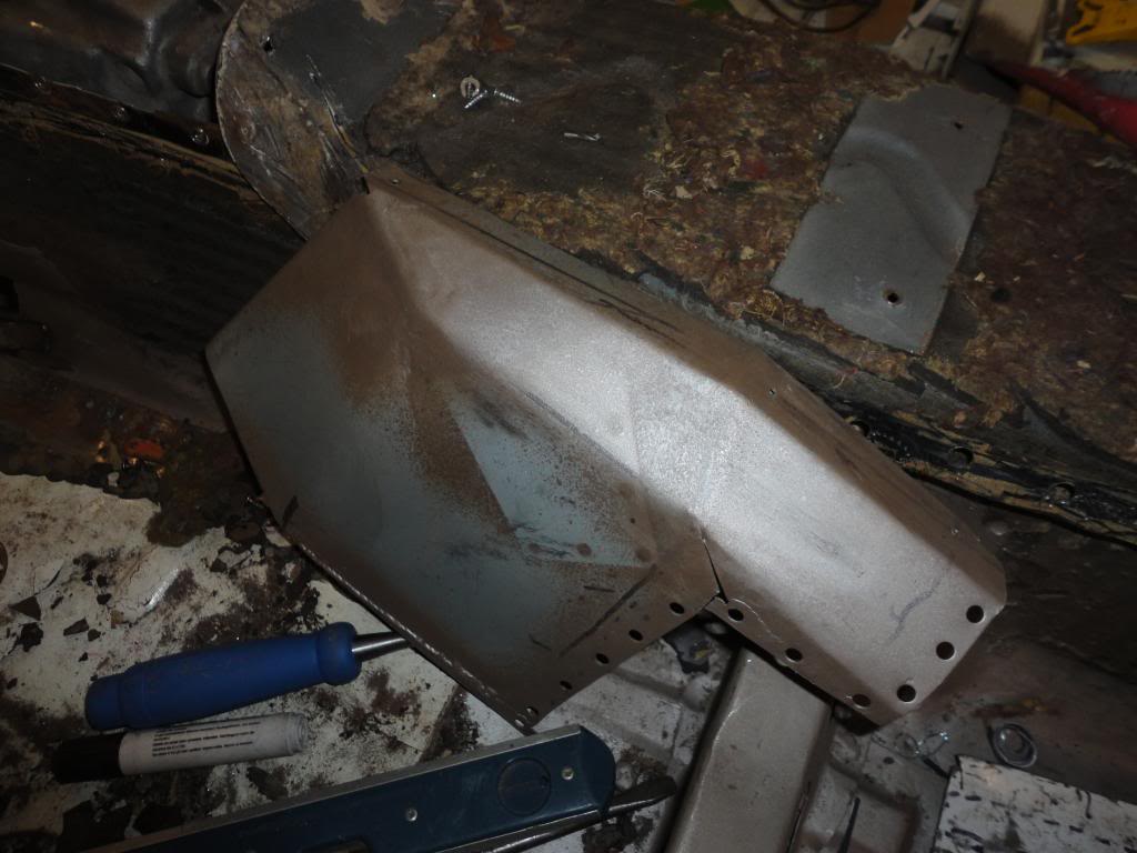
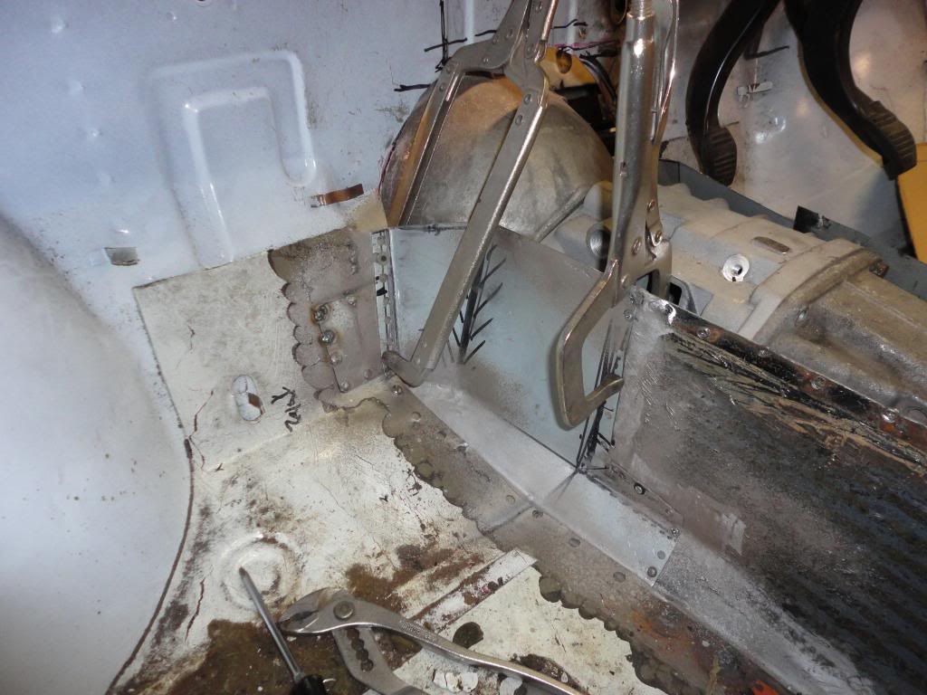
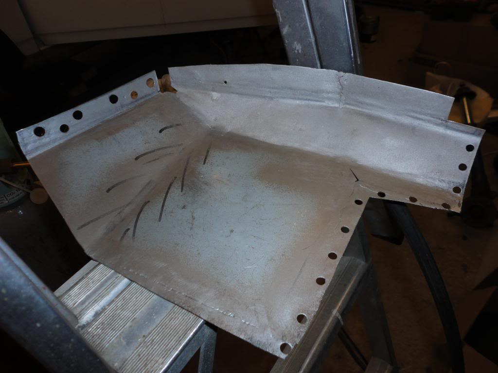
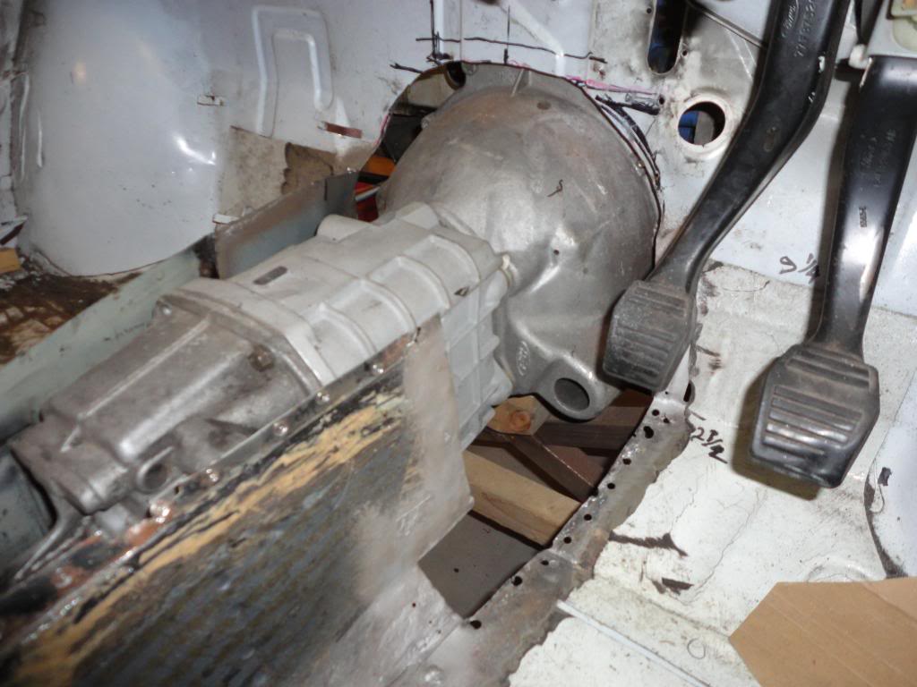
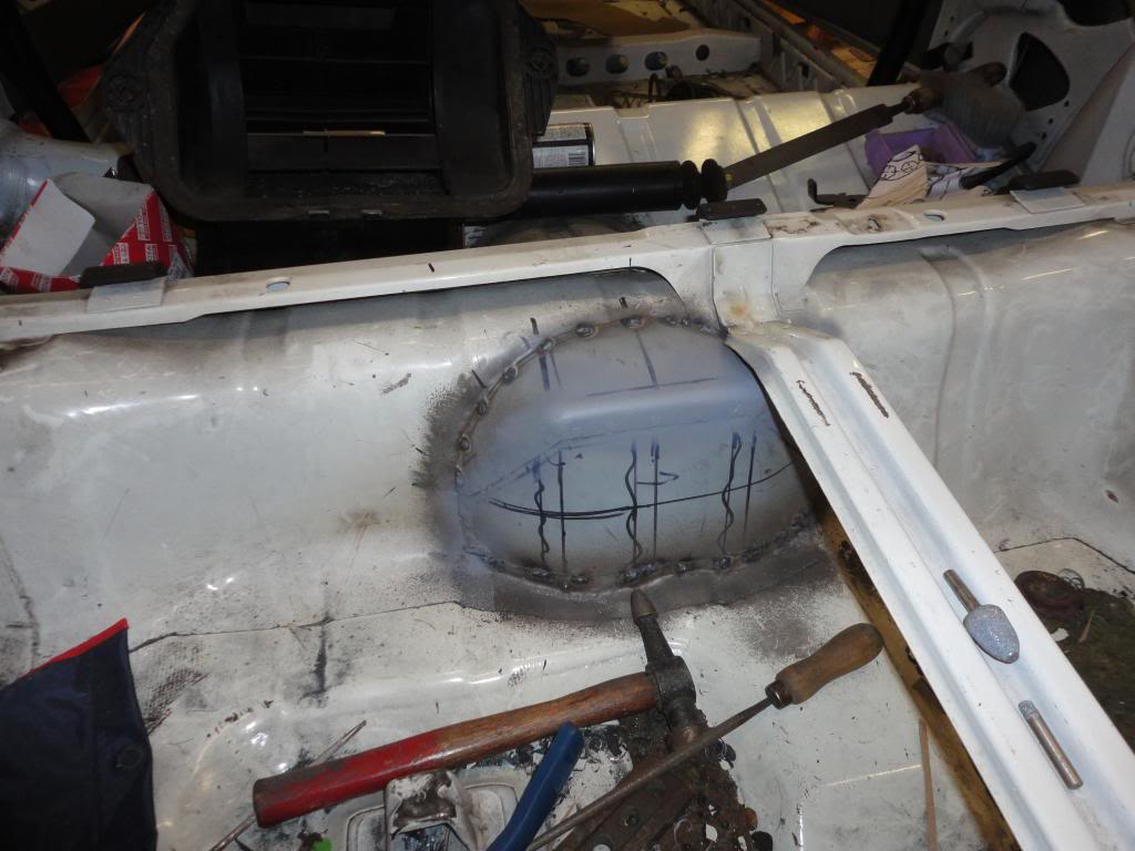
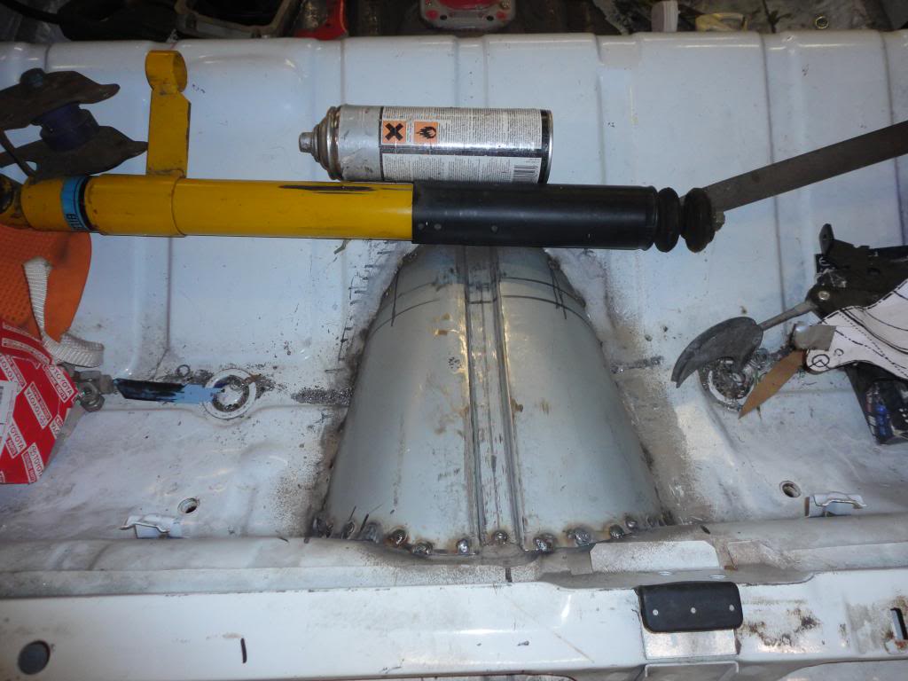
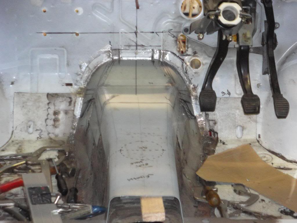
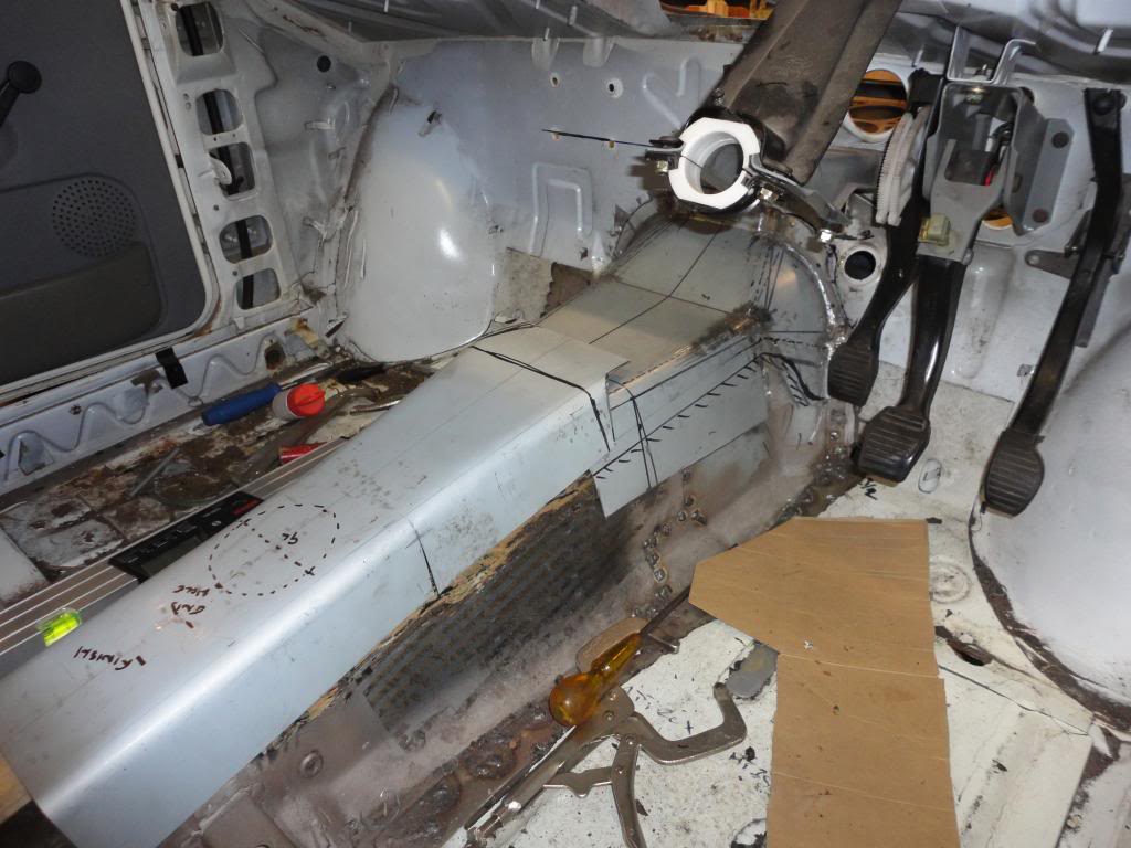
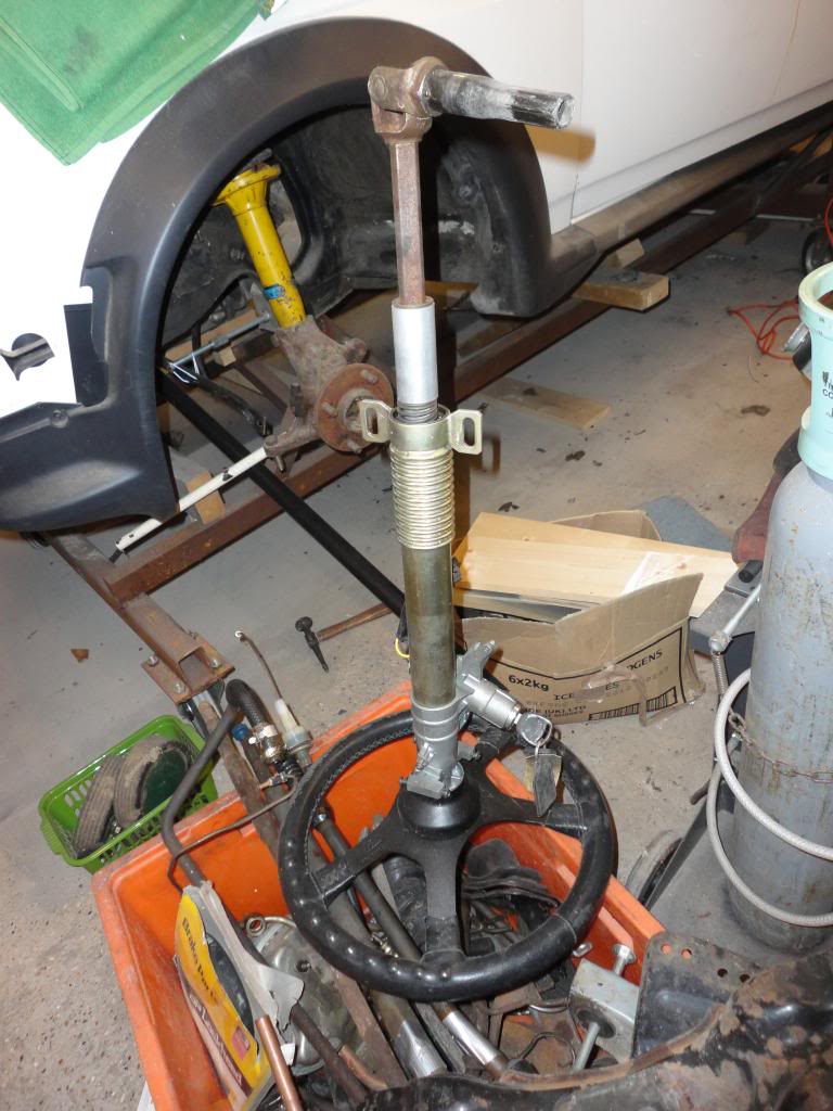
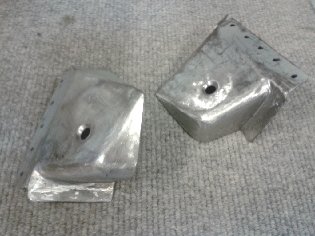
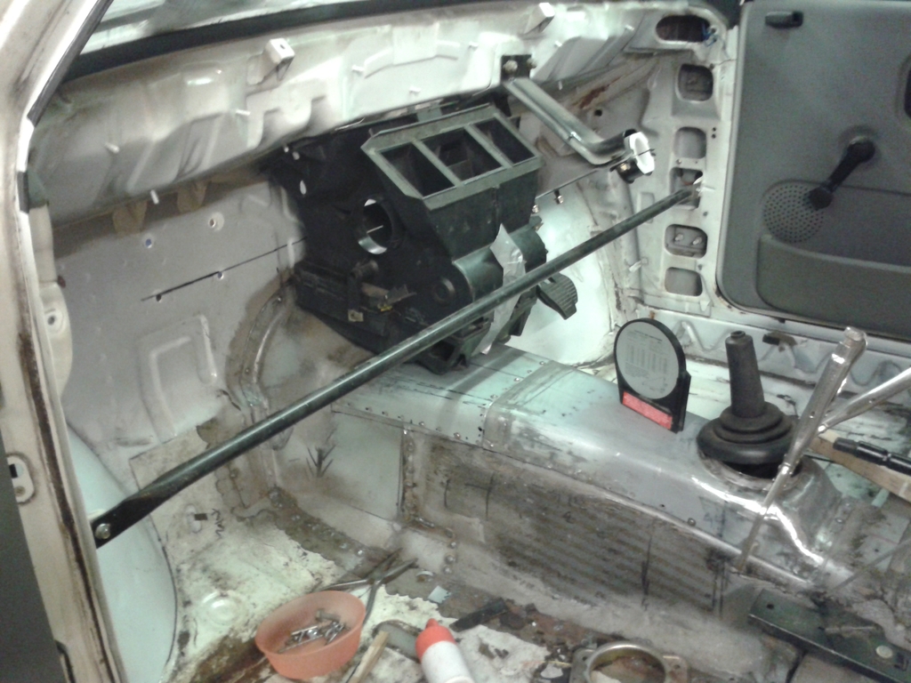
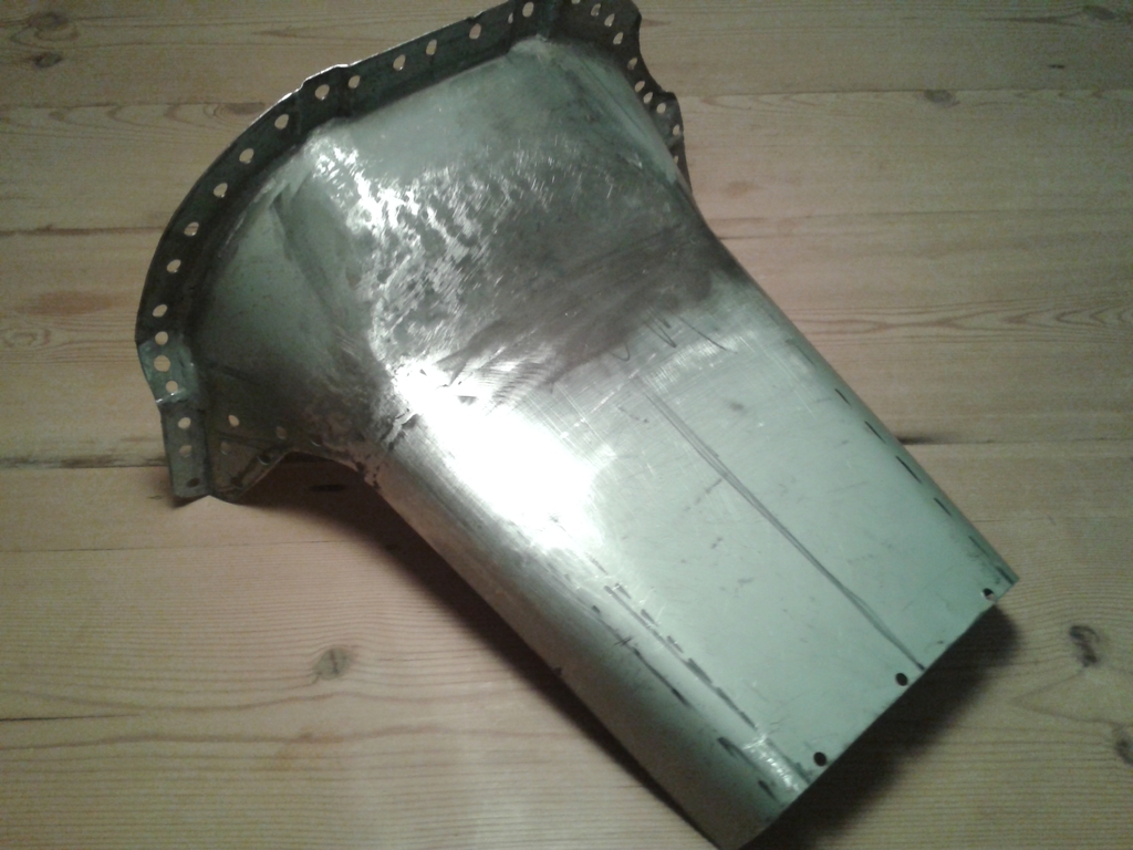
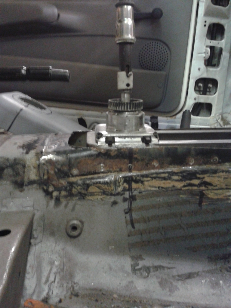
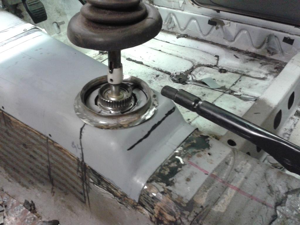
A few images. I hope they speak for themselves. some may be a bit out of context, but essentially got the front side sections of the tunnel in place. finished fabricating the top front section of the tunnel. still a bit of trimming to do, but essentially there. Started on the top middle part of the tunnel, but just got the metal roughly bent to shape, then hurt my back! got the diff covers made and in position. Tried to use the existing metal to make flanges. The idea to make the whole thing look as 'factory' as possible. The axle is just sitting there on axle stands to give me an idea of position.
The outer steering column now has a Sierra lower column bearing and with the use of an aluminium space is now fitted with a Fiesta Mk 3 inner column. Still a long way they but the column is one step nearer to what I need.
The USA seems to have a massive choice of steering UJ's and couplers, but nothing, so far what I need.


Last edited by rwd_fiesta; 08-12-2013 at 07:09 PM.
20-12-2013, 10:52 PM
#47
Not planning to use coil overs. I intend to use the Fiesta Bilstein rear shocks with the rear springs in the standard position, albeit lowered and uprated. The lower tie rods will be in the standard position but rose jointed both ends. There will also be two additional upper tie rods. Same effective length but curved to clear the floor above them so as not to make additional cuts in the floor. I will start on these over the Christmas period. I also need to cobble together a bespoke gear shift for the hybrid MT75 box.
23-12-2014, 03:56 PM
#48
I have been working away on the car and an update will be coming. Details and images to follow.
At present, I only have an old pinto block and head being used to line everything up, etc. The intention was always to use a YB Cosworth engine, but I'm now sort of veering towards a pinto turbo. Something a bit quirky. And possibly cheaper than a reasonable Cosworth unit. I have just bought a new gearbox and feel that maybe I should commit to finding the engine for this car sooner rather than later.
At present, I only have an old pinto block and head being used to line everything up, etc. The intention was always to use a YB Cosworth engine, but I'm now sort of veering towards a pinto turbo. Something a bit quirky. And possibly cheaper than a reasonable Cosworth unit. I have just bought a new gearbox and feel that maybe I should commit to finding the engine for this car sooner rather than later.
15-11-2016, 12:36 PM
#50
After a long break, I finally have a reasonable update. The break does not mean I have not been busy working on the car. In fact I have made some good progress.
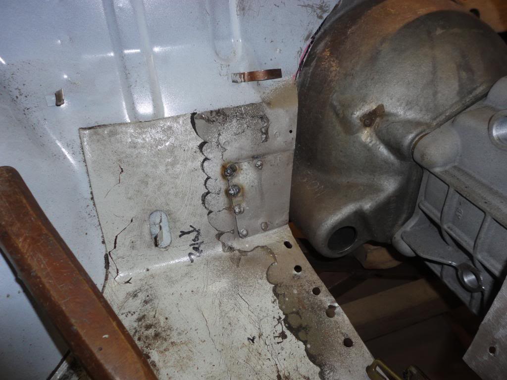
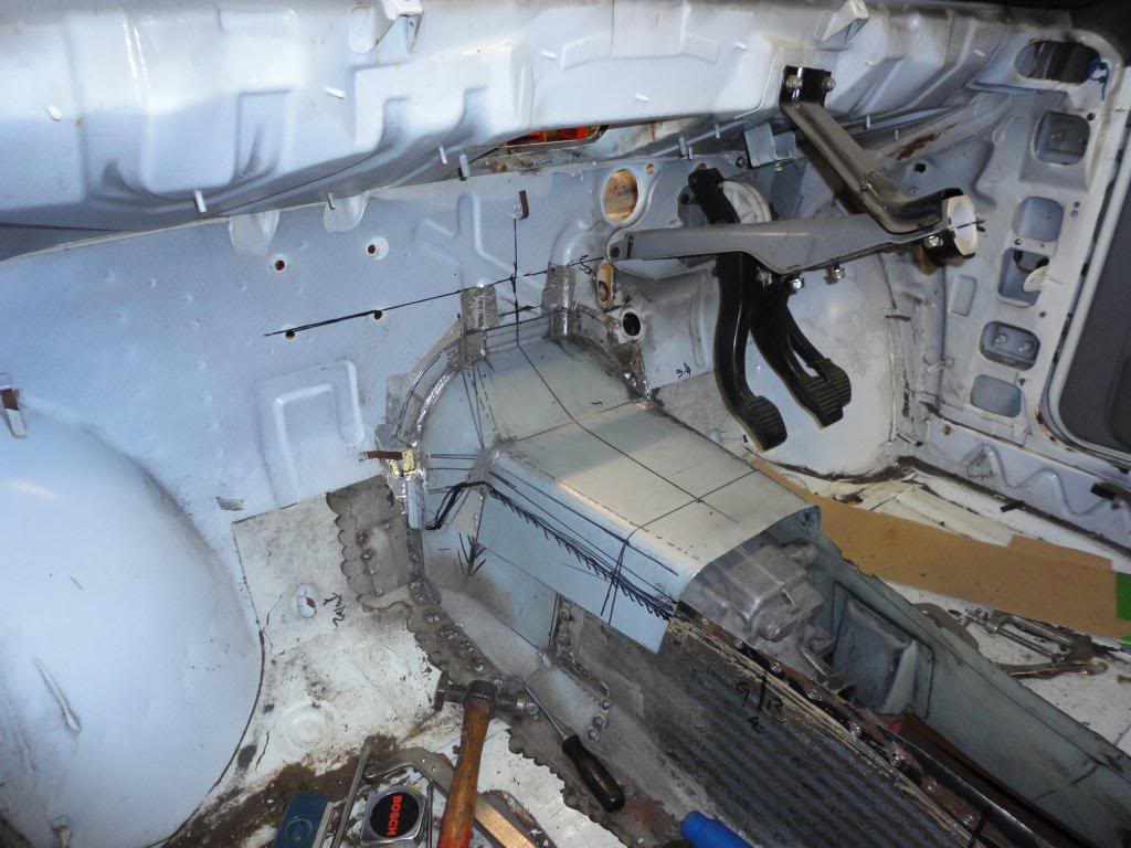
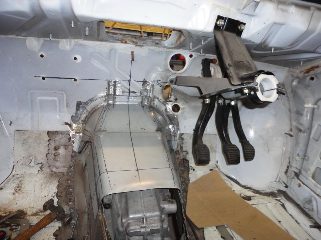
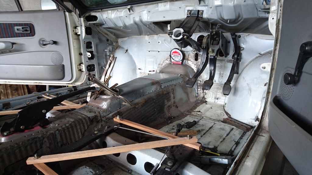
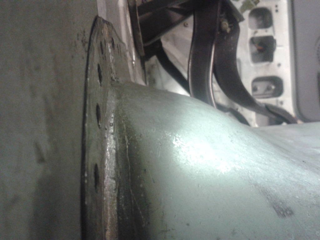
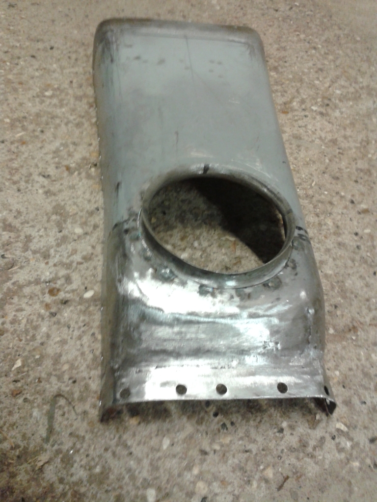
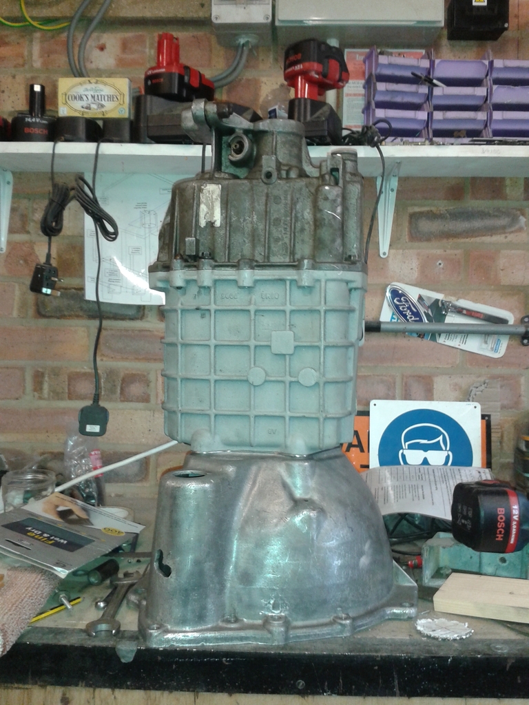
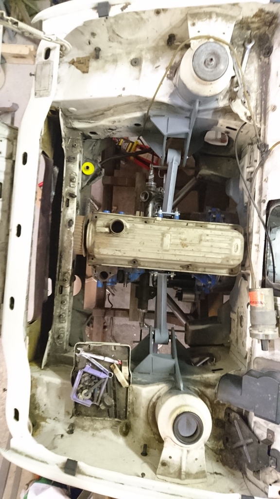
Although not 100% welded in, the transmission tunnel is now fully shaped and fettled. Fits the shell like a glove. It is now taller than the escort mk2 tunnel that forms the basis of the tunnel. This is to accommodate the MT75 casing. Getting the heater to fit has been a pain, but it does go in- just. The gear lever hole surround is pure Escort mk2 and is spot welded into position. The area around the gear lever is shaped to clear the MT75 gear lever frame.
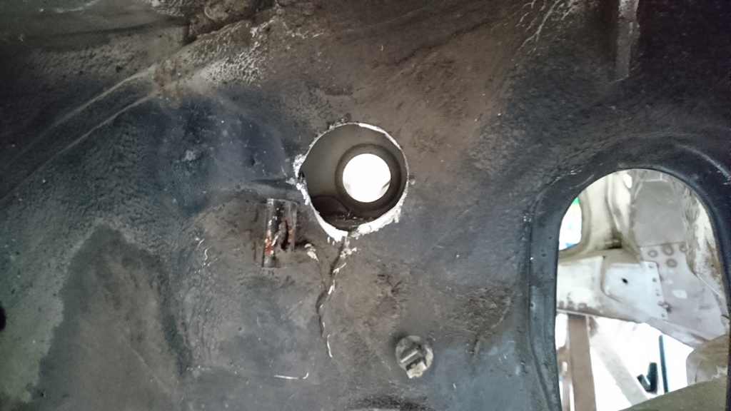
The tunnel is now fully welded to the bulkhead now and I have fabricated and fitted the lower bulkhead closing sections in the engine bay. Again, I�ve tried to make it all look factory finished.
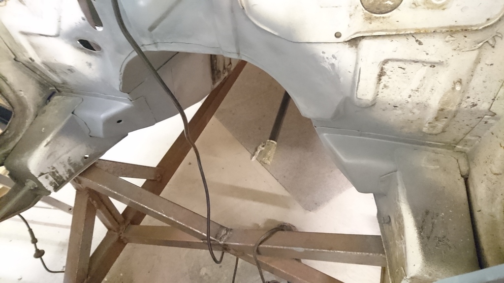
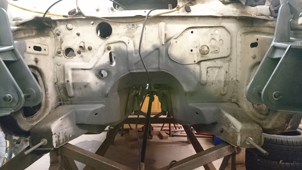
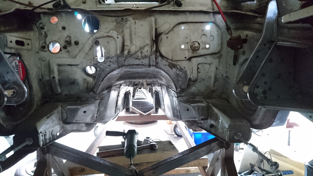
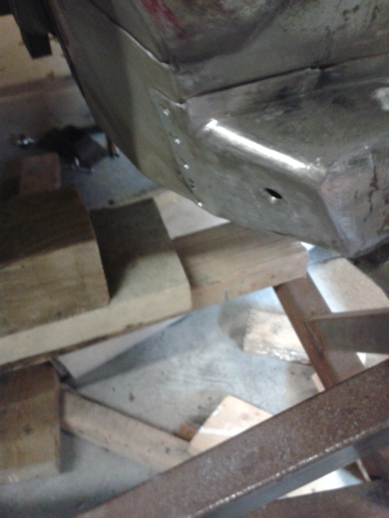
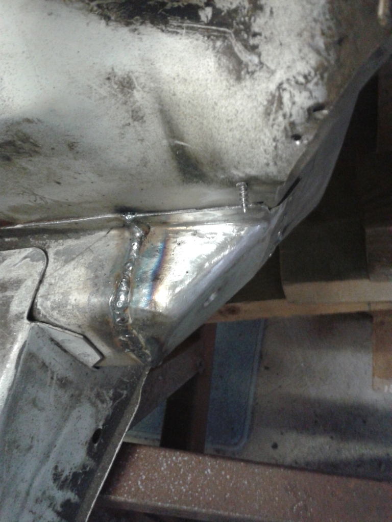
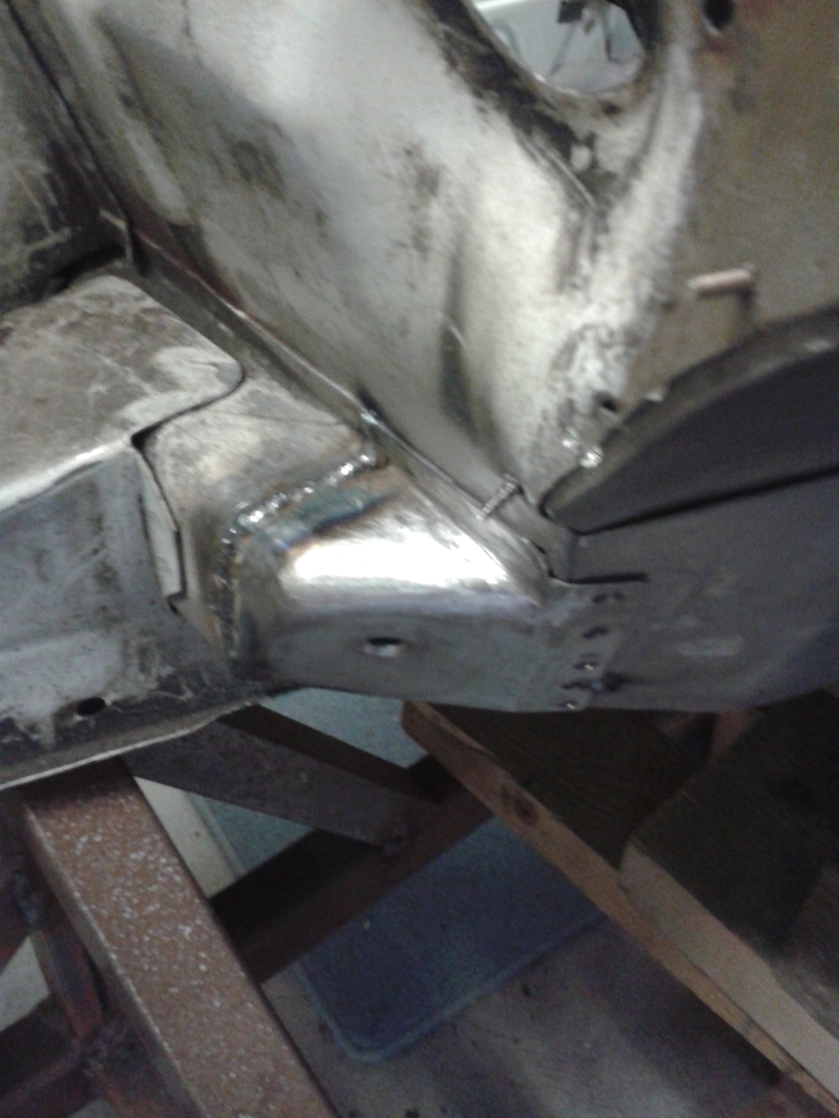
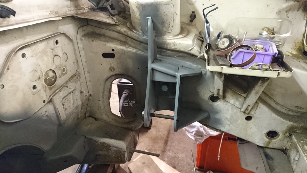
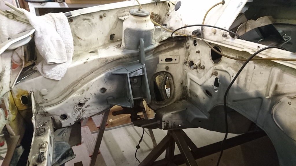
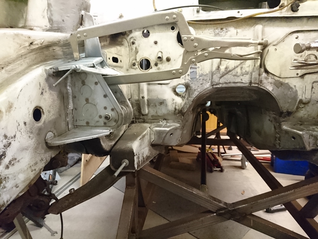
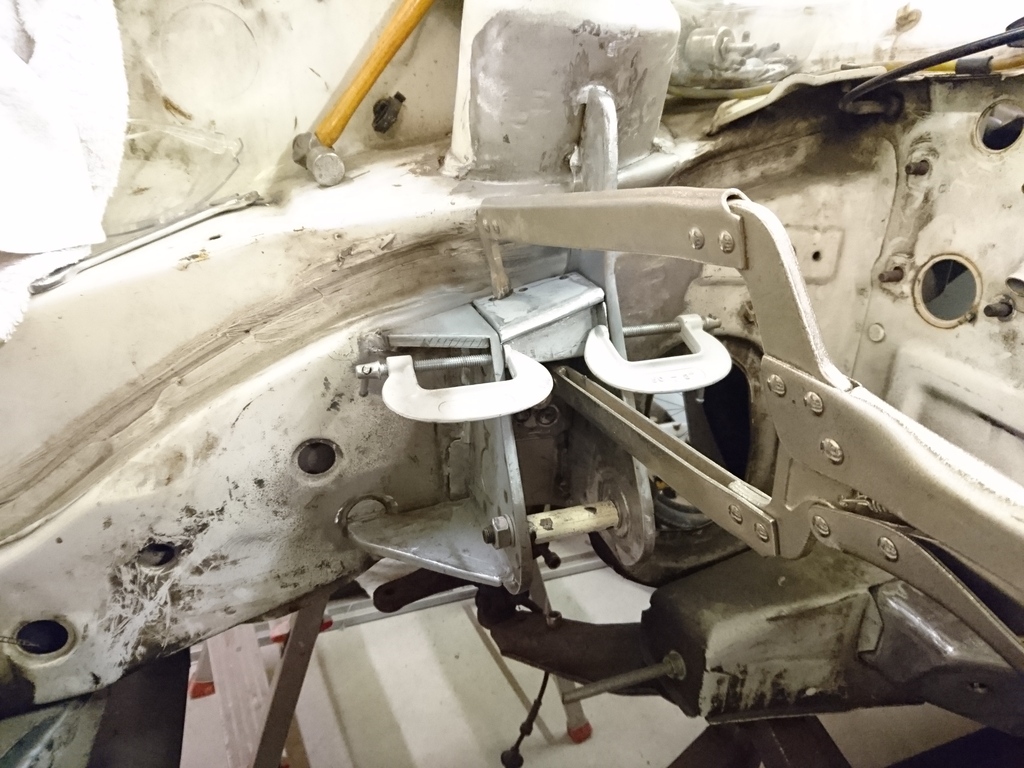
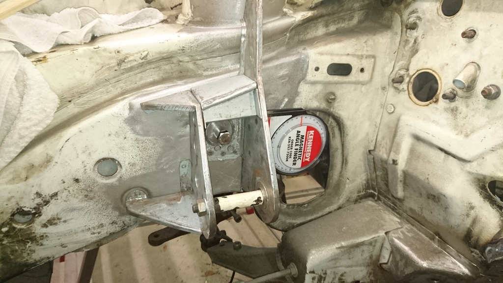
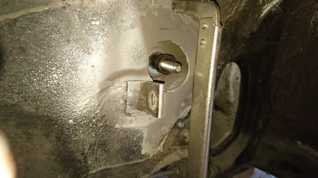
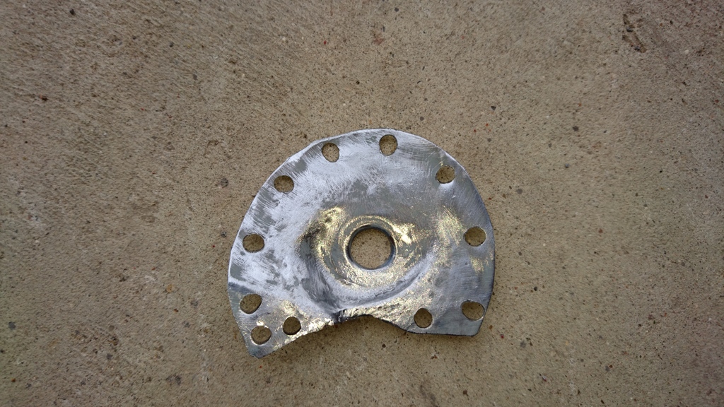
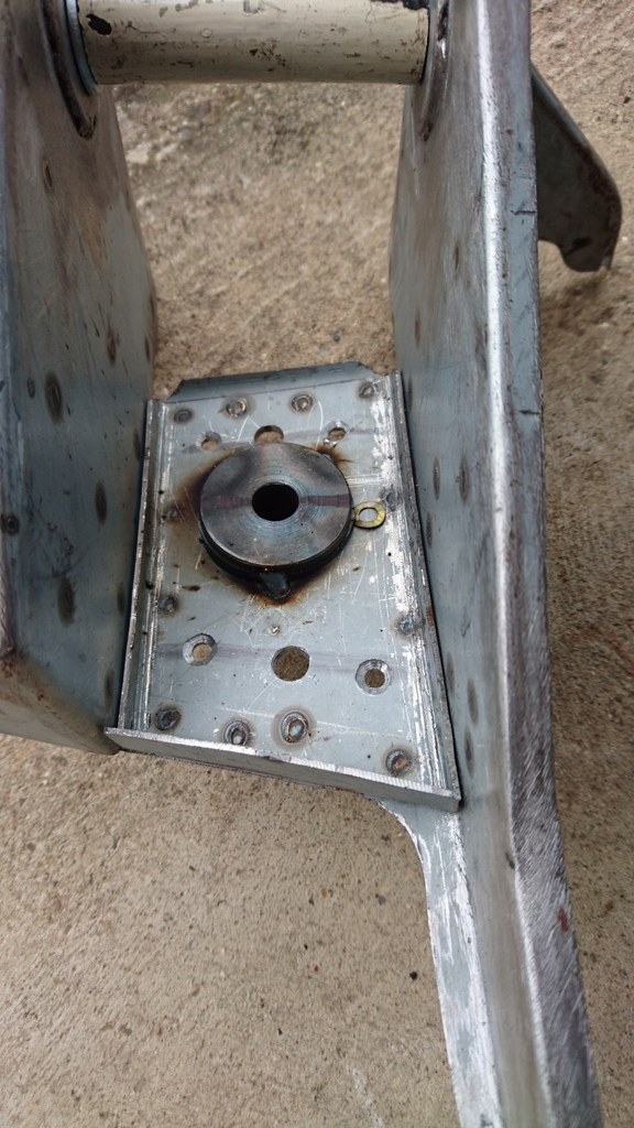
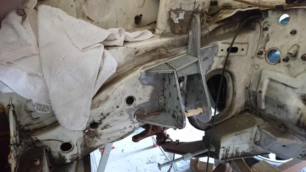
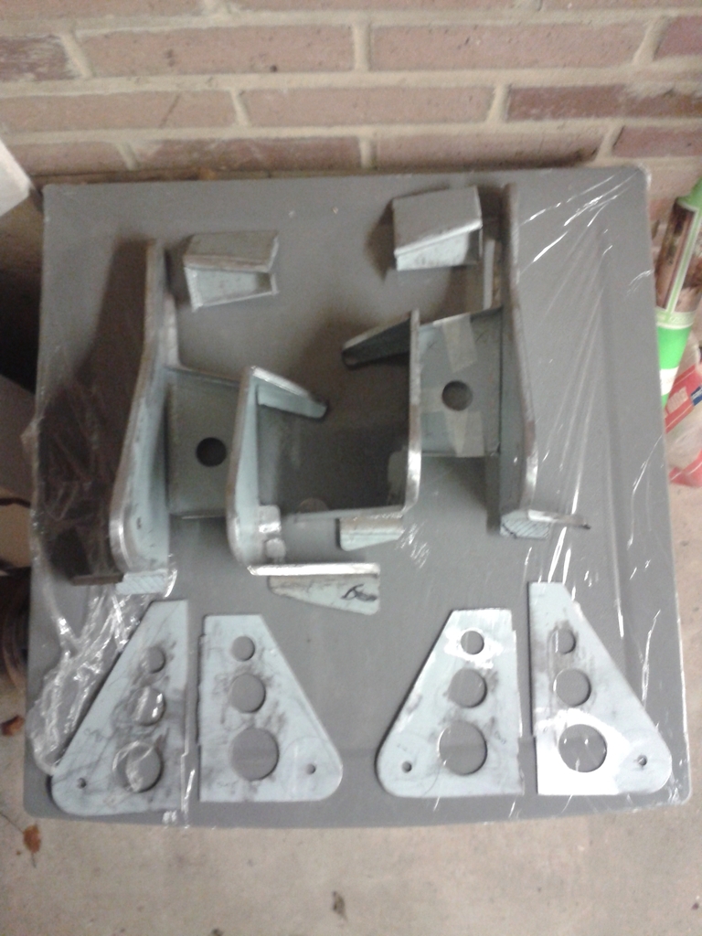
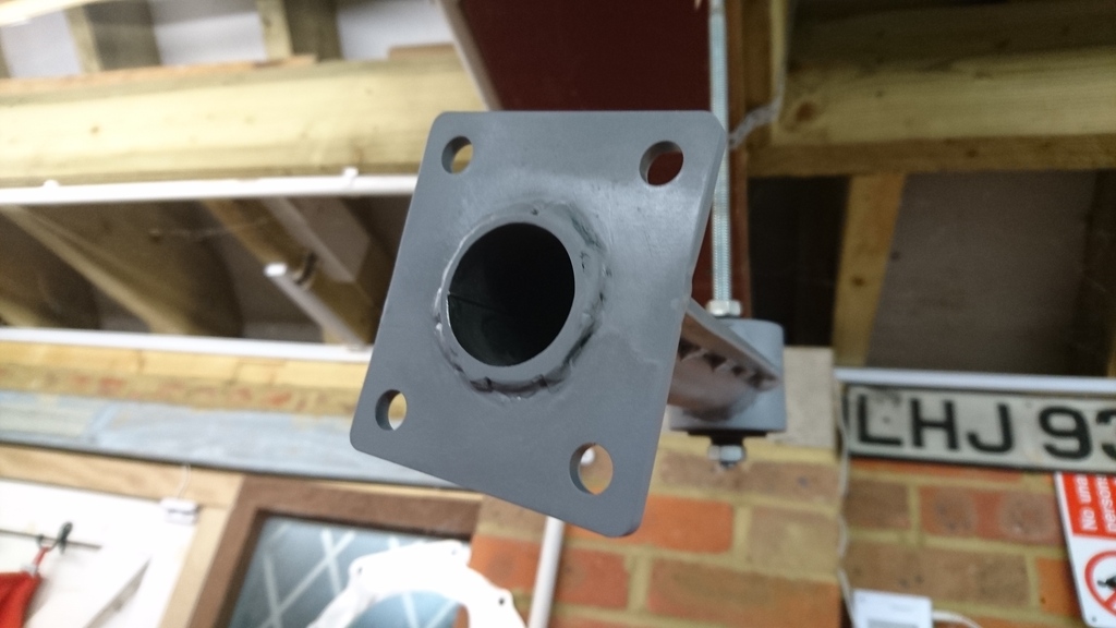
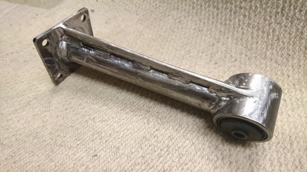
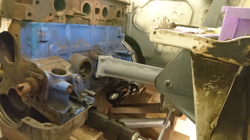
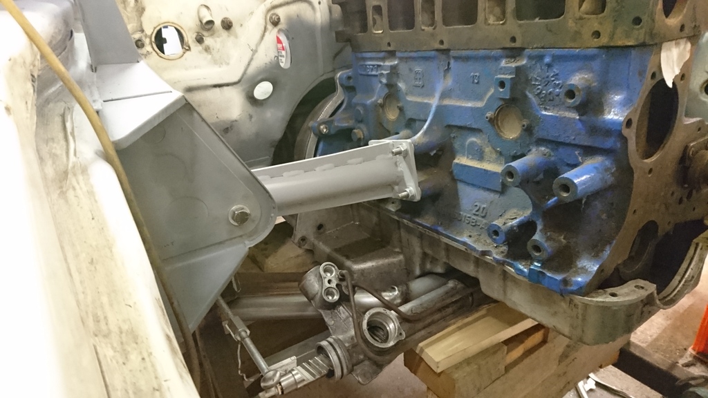
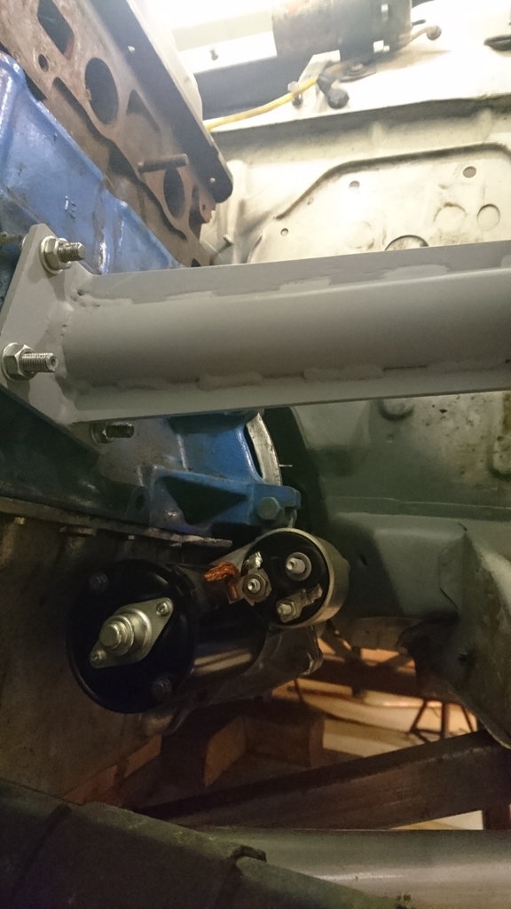
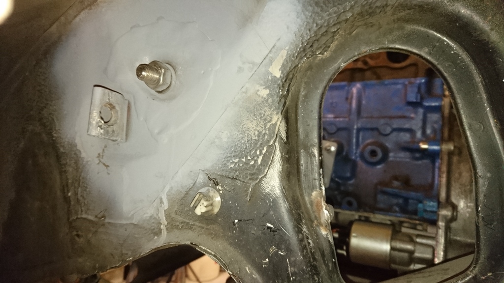
Whilst the dummy engine and gearbox were out, I have fabricated and welded in the engine mount brackets to the left and right hand chassis legs. I�ve tried to make these in the style of the original RS1700T design. They will utilise World Cup mounting bushes. The mounts also incorporate bolt holes to secure the steering rack sub-frame. These bolt holes use part of the old FWD engine mount bolt hole on the driver�s side inner wing and a matching hole grafted into the same position on the passenger side.
Now these are in, the dummy engine can go back in and the engine block part of the engine mounts can be made up. I�ll also make up a new streamlined gearbox cross member.
Due to the narrow nature of the transmission tunnel, I have had to make a new gear lever extension. It is essentially fabricated out of steel. The advantage of making this from scratch is the ability to make it as long or short as I want. The gear lever pivot is pure Sierra, but with a spacer added to accommodate the short shift kit. The kit is modified to allow the gear lever to stand vertically in neutral. I have yet to make the reverse gear interlock and triangular strengthening links. The linkage is from a 4x4 model, suitably shortened.
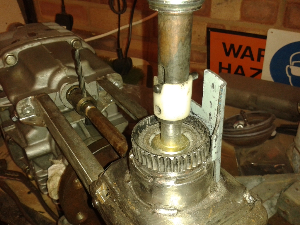
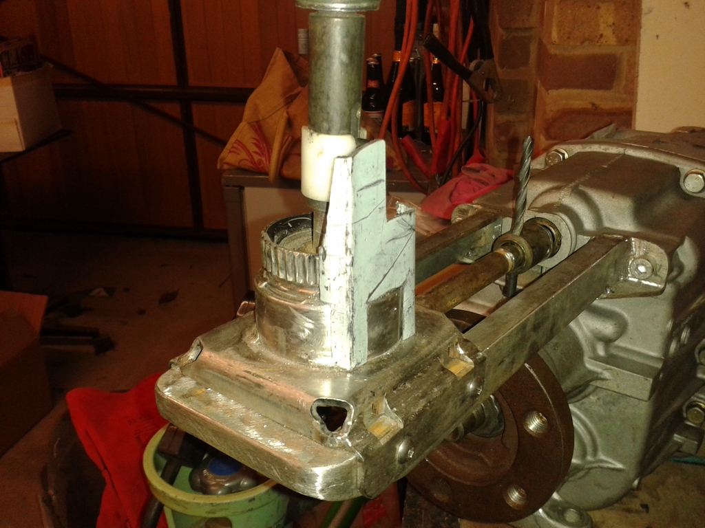
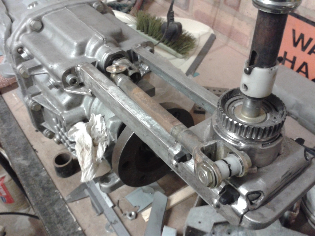
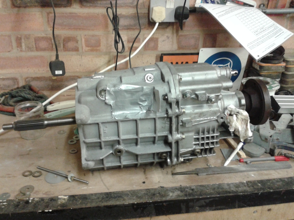
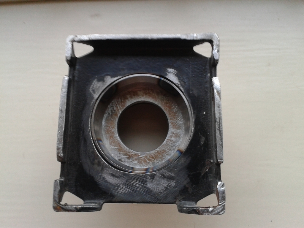
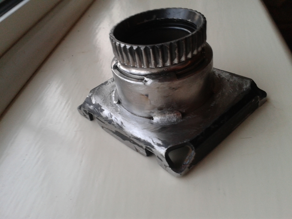
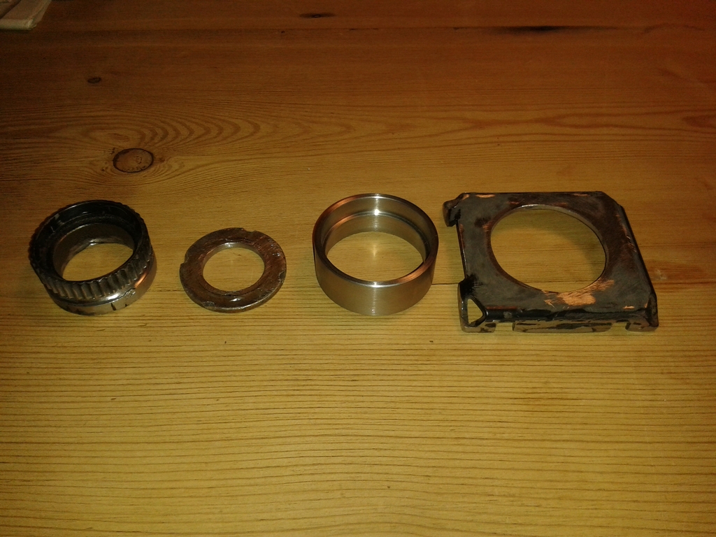
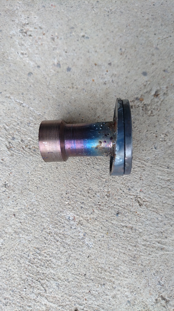
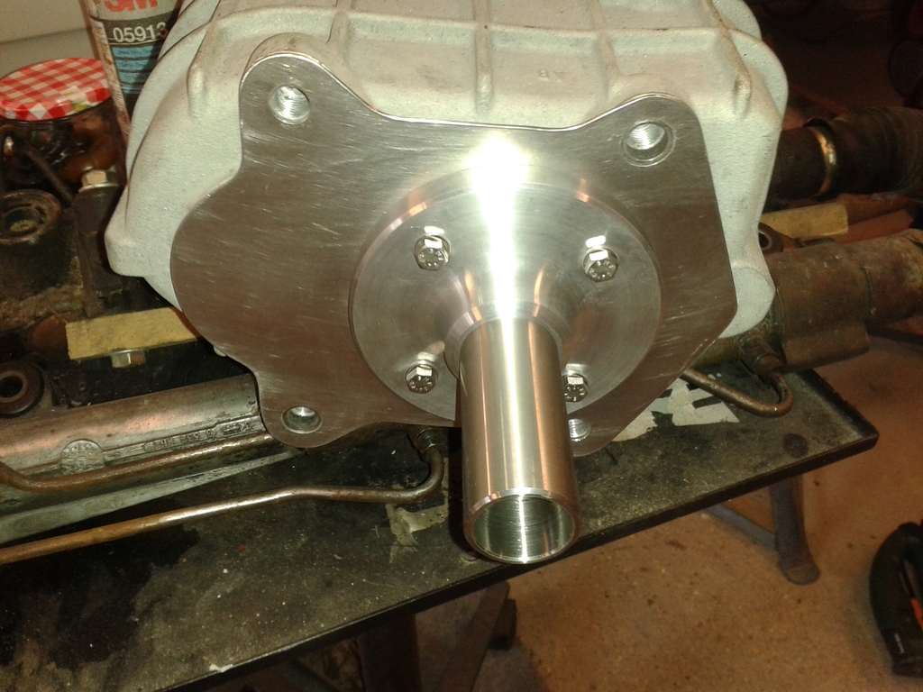
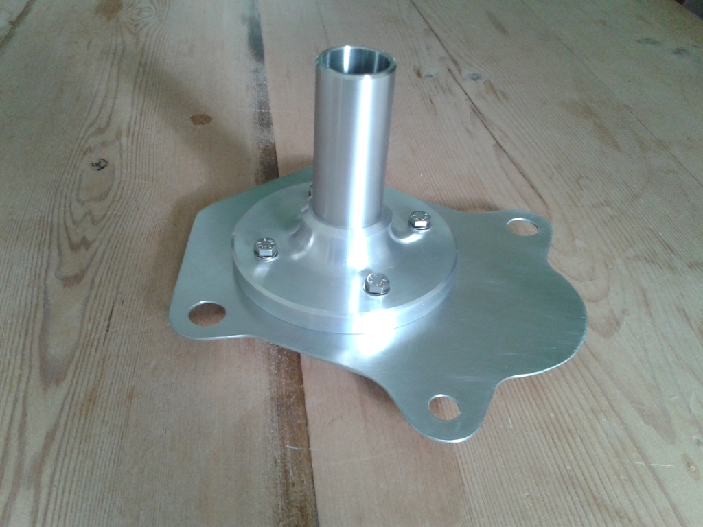
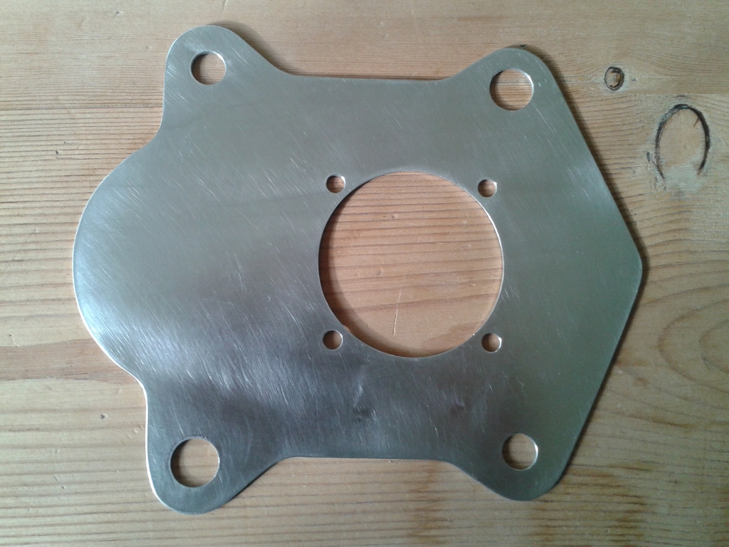
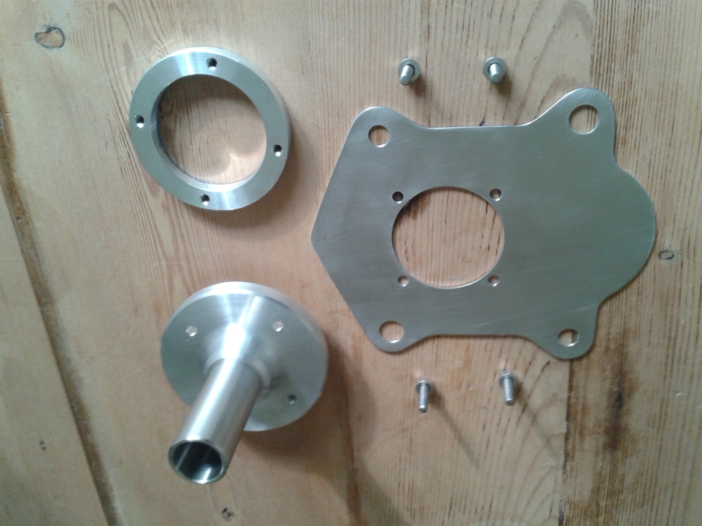
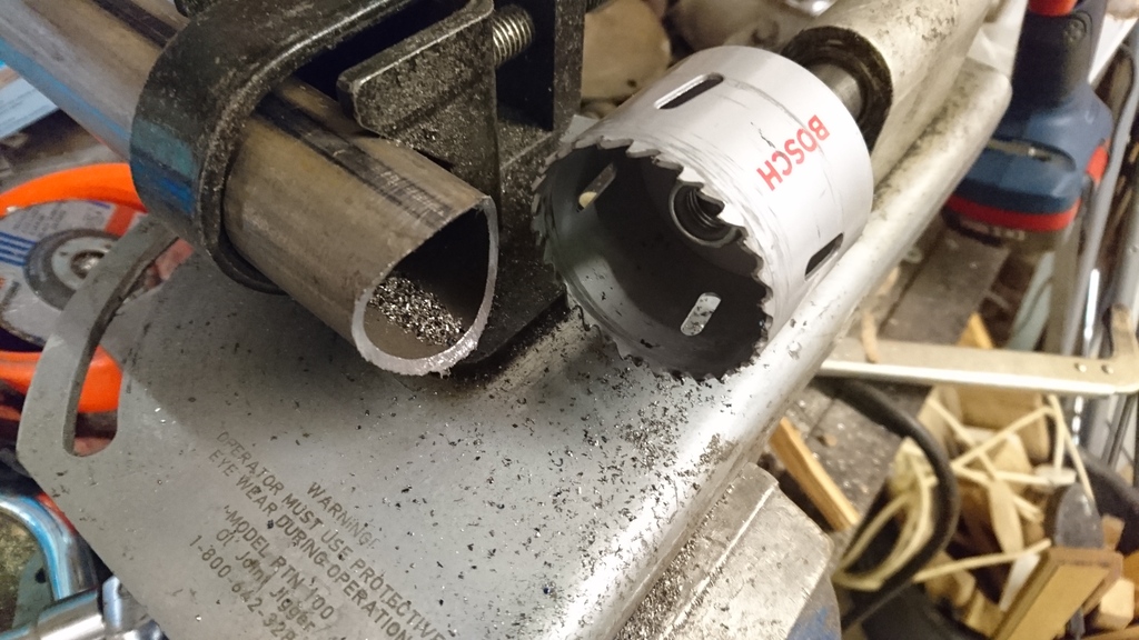
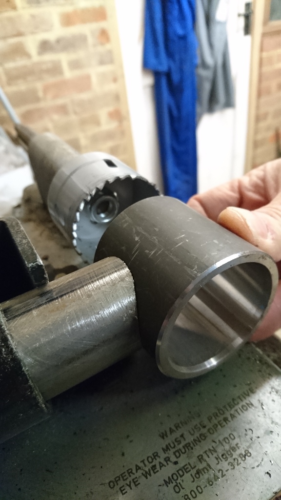
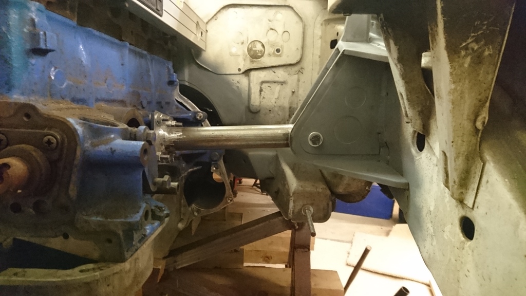
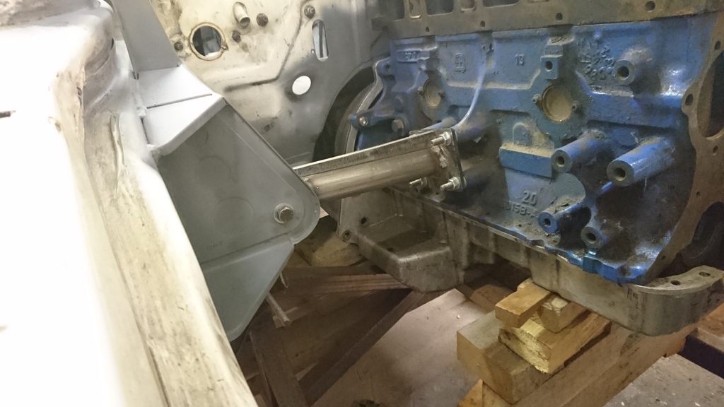
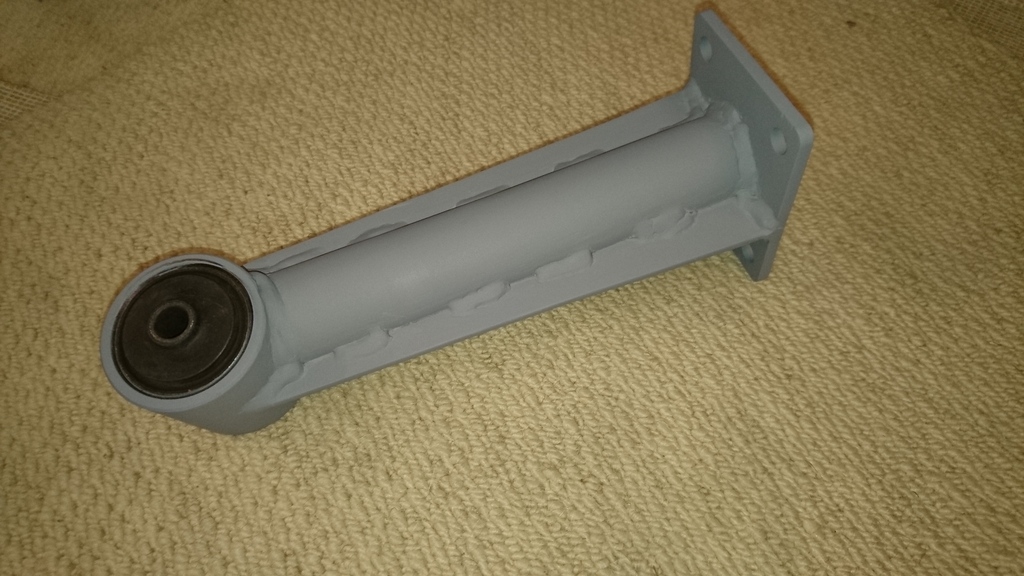
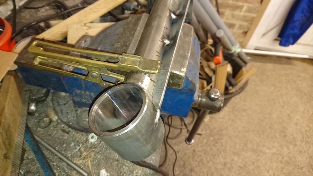
The hybrid MT75 gearbox casing fits the RS2000 alloy bellhousing perfectly, but there is no release bearing guide tube. In order to accommodate this, I have designed a stainless steel adaptor plate which is sandwiched between the main casing and bellhousing. To that is bolted a bespoke guide tube made of aluminium alloy and steel. This also has the additional function of giving additional concentric location between the 2 parts. All this was incorporated when I thought cable clutch was the way to go. I�m now thing hydraulic, but final decision not made yet.
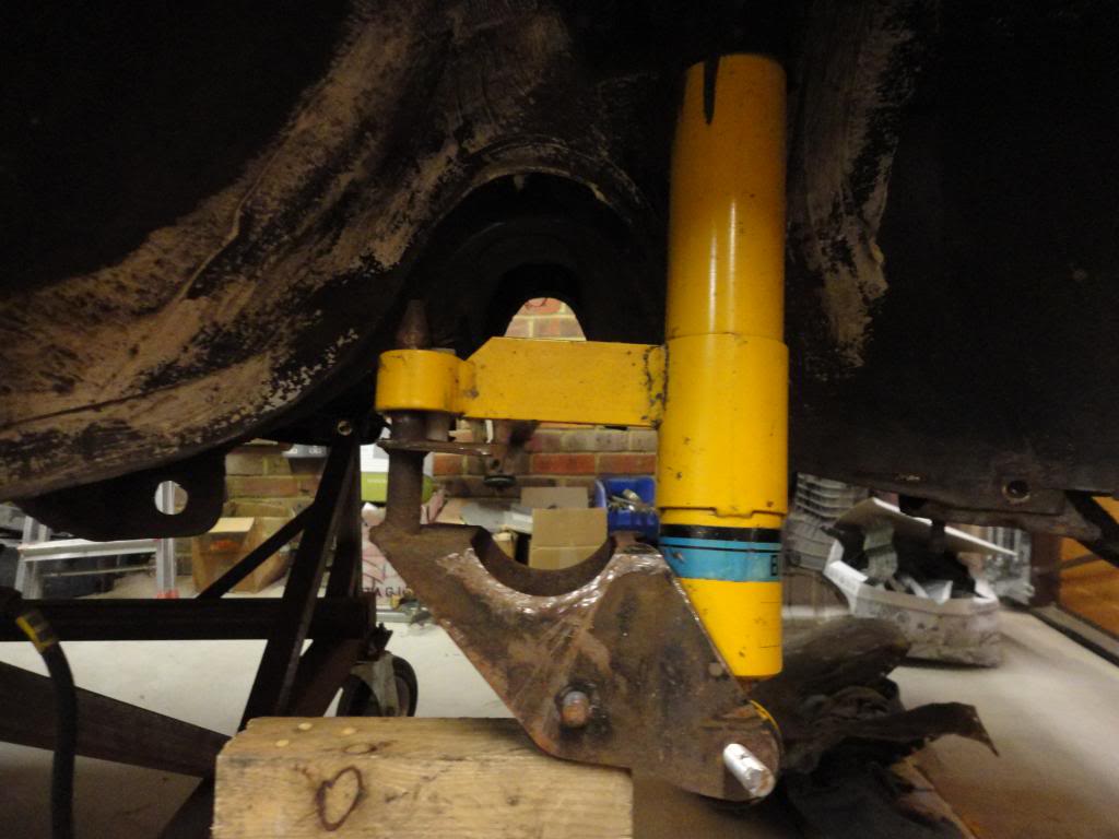
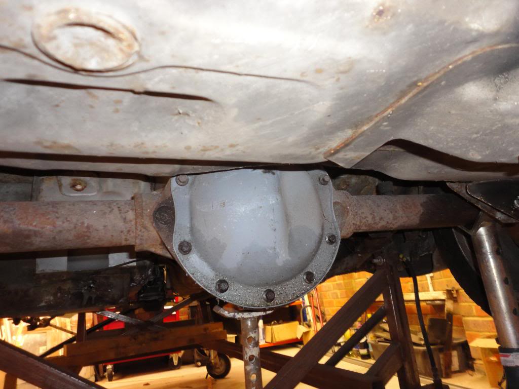
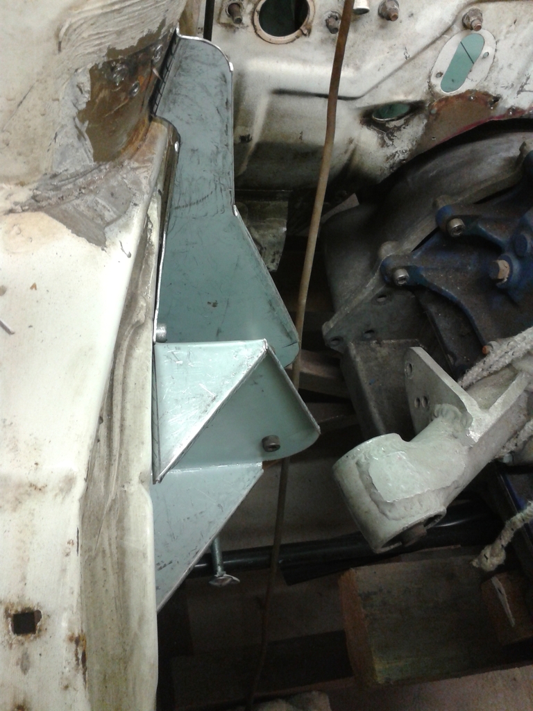
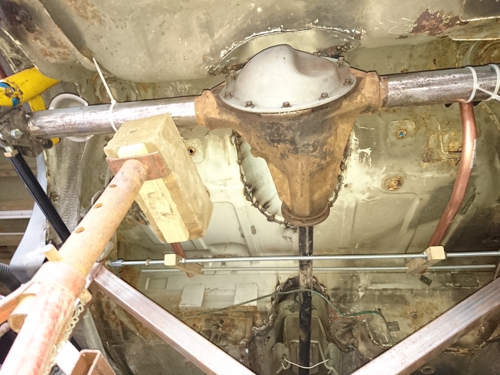
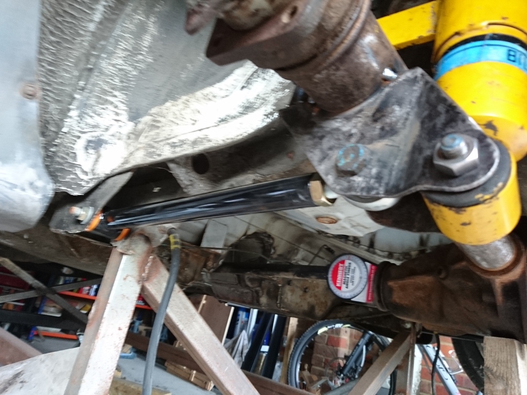
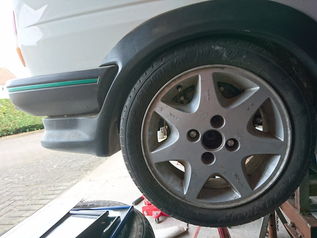
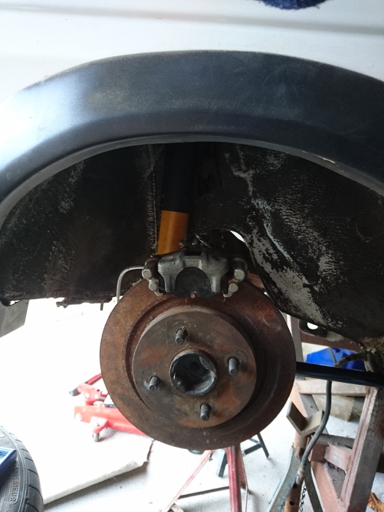
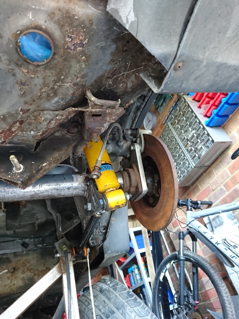
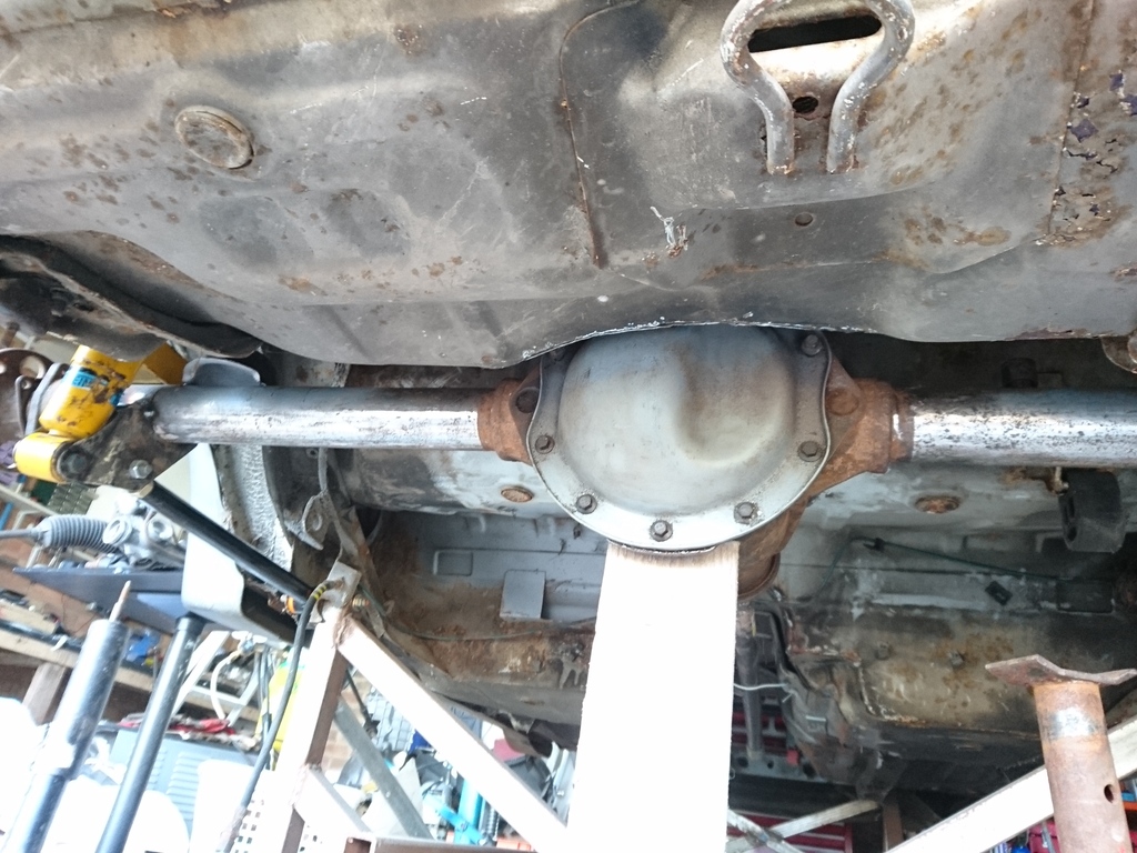
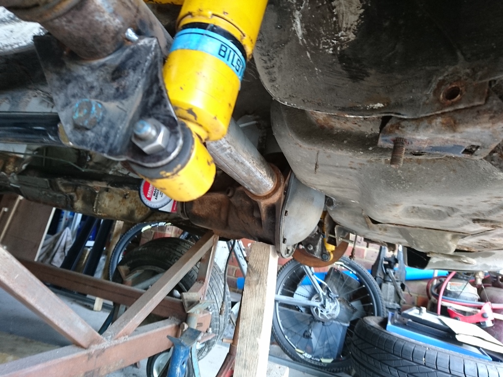
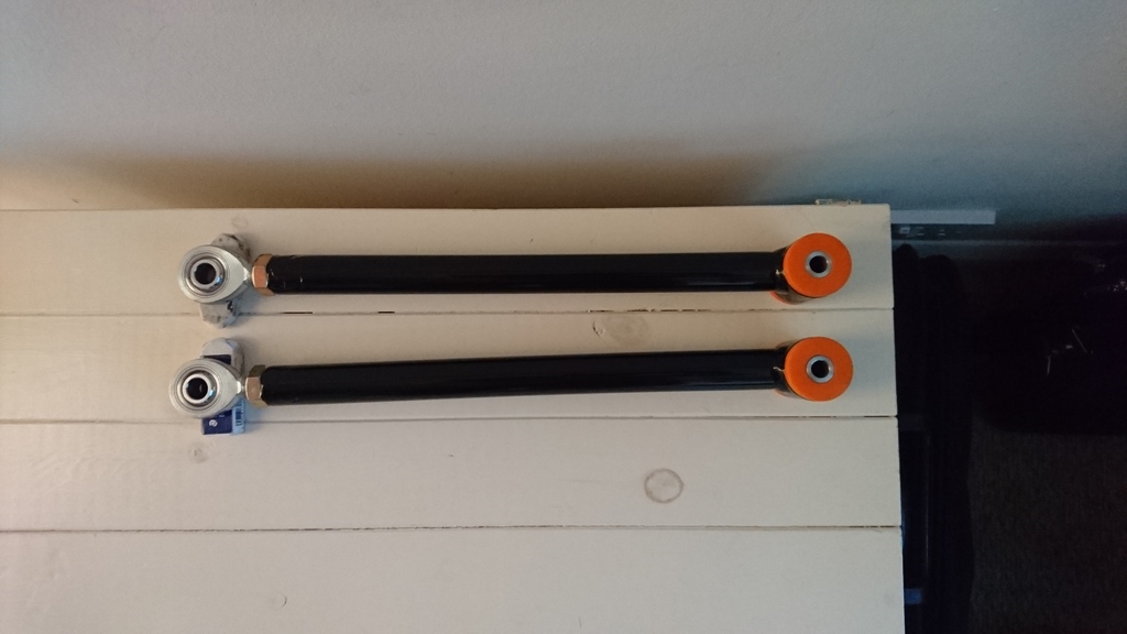
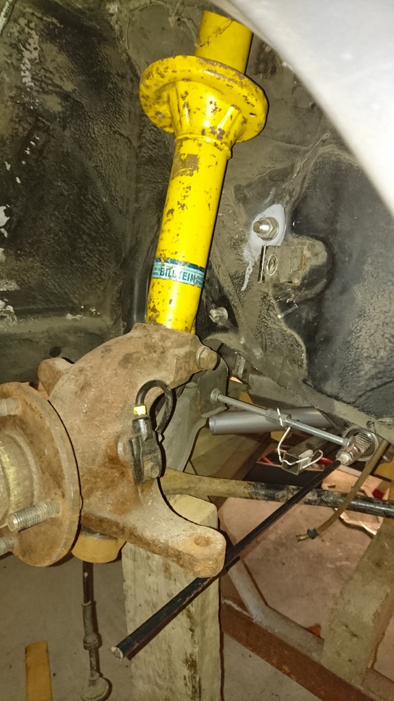
I have also tacked the original Fiesta brackets onto the Atlas axle. The axle is now mounted on the car. It is held in place with 2 new lower tie rods. Both adjustable (bush one end and spherical bearing the other). I now need to get the panhard rod welded up. This is kinked to clear the diff, but otherwise uses the standard mounting points. The shocks are Fiesta Bilstein units and I have just go a set of Gaz minus 1 inch springs to see how they fit.
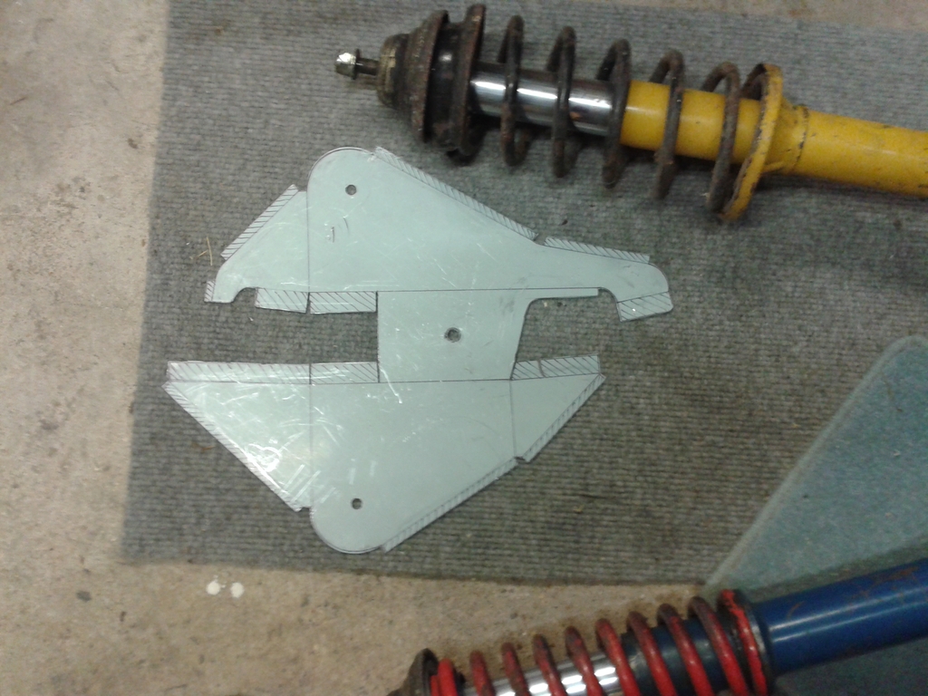
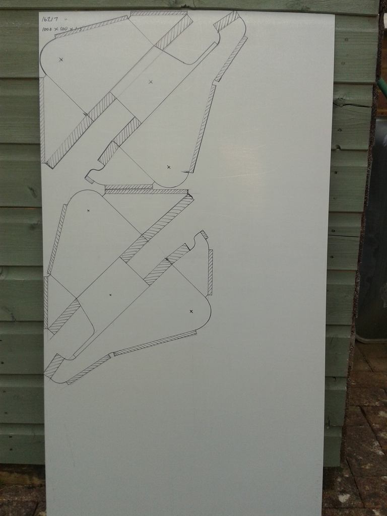
I also need to fit upper tie rods to aid with axle location. This has proved a very interesting exercise. In order to establish the body side pivot position, I created a full size mock-up of the rear suspension that could move the full length of travel. The result was surprising. In order to get a pivot point that was in a true neutral position in all angles of travel, the upper bar needs to be nearly 600mm long. This is in stark comparison to the standard length lower arms which are just over 300mm long. I�ve seen other conversions where the upper arms are the same or even shorter and I know many of these cars suffer from metal fatigue around the mounting points on the bodyshell. Hopefully I can eradicate this problem.
The upper arms will also be kinked to clear the floor. I didn�t want to cut channels for them so I can retain the rear seats if I want to.
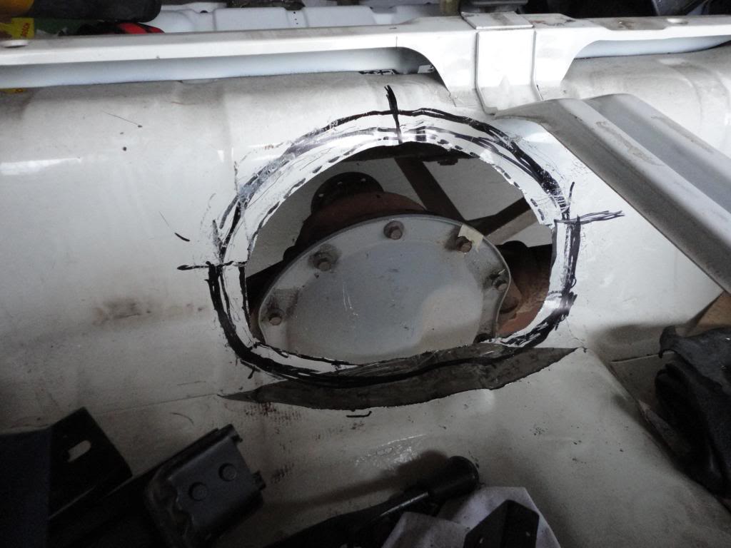
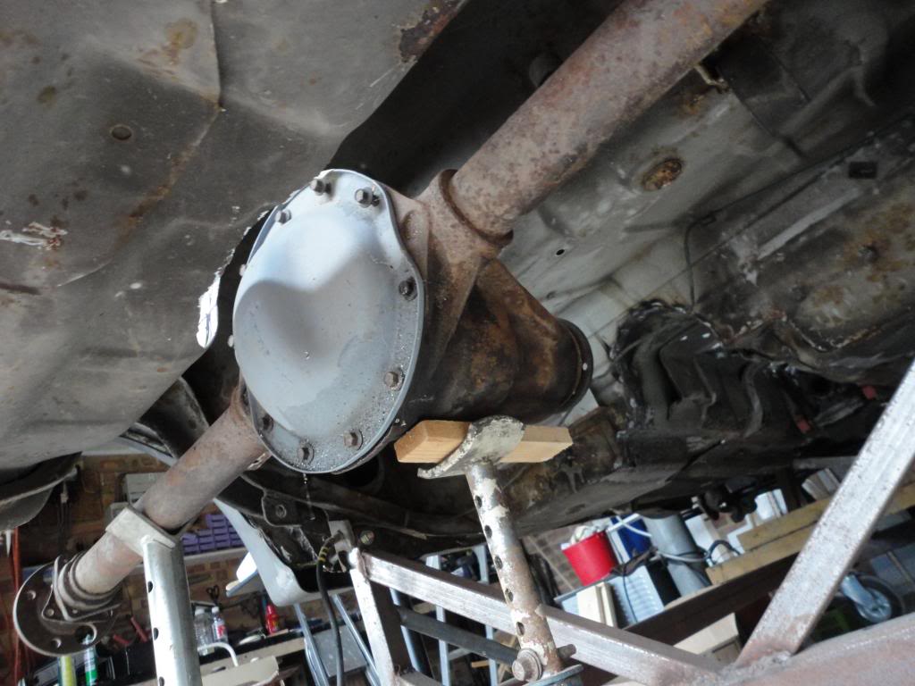
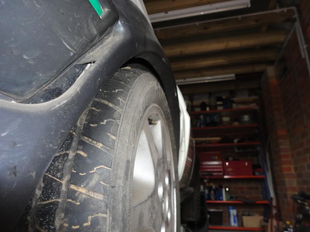
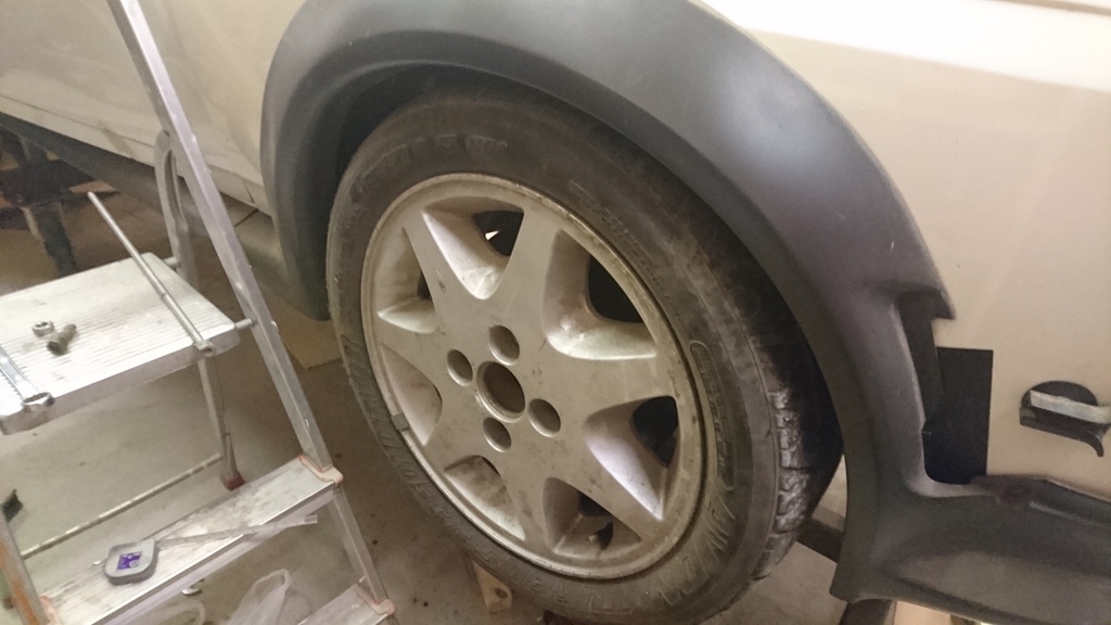
The nose of the diff at normal ride height is pointing up 4 degrees (same as the engine angle). The proposed alignment of the prop looks ok. I�ve also mount a wheel on one side. With the 52 inch axle, wheel clearance under the XR2 kit is very tight, but I�ll deal with that later down the road.
I seem to have more enthusiasm now things are progressing. There is still a ton of unanswered issues, but I will hopefully get the car rolling by next May.
Although not 100% welded in, the transmission tunnel is now fully shaped and fettled. Fits the shell like a glove. It is now taller than the escort mk2 tunnel that forms the basis of the tunnel. This is to accommodate the MT75 casing. Getting the heater to fit has been a pain, but it does go in- just. The gear lever hole surround is pure Escort mk2 and is spot welded into position. The area around the gear lever is shaped to clear the MT75 gear lever frame.
The tunnel is now fully welded to the bulkhead now and I have fabricated and fitted the lower bulkhead closing sections in the engine bay. Again, I�ve tried to make it all look factory finished.


Whilst the dummy engine and gearbox were out, I have fabricated and welded in the engine mount brackets to the left and right hand chassis legs. I�ve tried to make these in the style of the original RS1700T design. They will utilise World Cup mounting bushes. The mounts also incorporate bolt holes to secure the steering rack sub-frame. These bolt holes use part of the old FWD engine mount bolt hole on the driver�s side inner wing and a matching hole grafted into the same position on the passenger side.
Now these are in, the dummy engine can go back in and the engine block part of the engine mounts can be made up. I�ll also make up a new streamlined gearbox cross member.


Due to the narrow nature of the transmission tunnel, I have had to make a new gear lever extension. It is essentially fabricated out of steel. The advantage of making this from scratch is the ability to make it as long or short as I want. The gear lever pivot is pure Sierra, but with a spacer added to accommodate the short shift kit. The kit is modified to allow the gear lever to stand vertically in neutral. I have yet to make the reverse gear interlock and triangular strengthening links. The linkage is from a 4x4 model, suitably shortened.


The hybrid MT75 gearbox casing fits the RS2000 alloy bellhousing perfectly, but there is no release bearing guide tube. In order to accommodate this, I have designed a stainless steel adaptor plate which is sandwiched between the main casing and bellhousing. To that is bolted a bespoke guide tube made of aluminium alloy and steel. This also has the additional function of giving additional concentric location between the 2 parts. All this was incorporated when I thought cable clutch was the way to go. I�m now thing hydraulic, but final decision not made yet.


I have also tacked the original Fiesta brackets onto the Atlas axle. The axle is now mounted on the car. It is held in place with 2 new lower tie rods. Both adjustable (bush one end and spherical bearing the other). I now need to get the panhard rod welded up. This is kinked to clear the diff, but otherwise uses the standard mounting points. The shocks are Fiesta Bilstein units and I have just go a set of Gaz minus 1 inch springs to see how they fit.
I also need to fit upper tie rods to aid with axle location. This has proved a very interesting exercise. In order to establish the body side pivot position, I created a full size mock-up of the rear suspension that could move the full length of travel. The result was surprising. In order to get a pivot point that was in a true neutral position in all angles of travel, the upper bar needs to be nearly 600mm long. This is in stark comparison to the standard length lower arms which are just over 300mm long. I�ve seen other conversions where the upper arms are the same or even shorter and I know many of these cars suffer from metal fatigue around the mounting points on the bodyshell. Hopefully I can eradicate this problem.
The upper arms will also be kinked to clear the floor. I didn�t want to cut channels for them so I can retain the rear seats if I want to.
The nose of the diff at normal ride height is pointing up 4 degrees (same as the engine angle). The proposed alignment of the prop looks ok. I�ve also mount a wheel on one side. With the 52 inch axle, wheel clearance under the XR2 kit is very tight, but I�ll deal with that later down the road.


I seem to have more enthusiasm now things are progressing. There is still a ton of unanswered issues, but I will hopefully get the car rolling by next May.
15-11-2016, 04:22 PM
#51
Passionford Addict
I don't know how but I seem to have missed this thread when it first started 
As you'll see by my screen name and sig I love my old mk2s and always fancied building a rear drive one but got something else up my sleeve to build after the new year
Got to say tho your doing a cracking job of this and that's me subscribed
Keep at it
As you'll see by my screen name and sig I love my old mk2s and always fancied building a rear drive one but got something else up my sleeve to build after the new year
Got to say tho your doing a cracking job of this and that's me subscribed
Keep at it
15-11-2016, 08:44 PM
#53
Passionford Addict
 19-11-2016, 01:11 PM
#54
Advanced PassionFord User
A brilliant project, and amazing fabrication skills, and an interesting read  one to watch
19-11-2016, 02:44 PM
#55
10K+ Poster!!


Really nicely written and fabulous work, please keep the updates coming
20-11-2016, 06:06 PM
#56
Thanks for the positive comments.
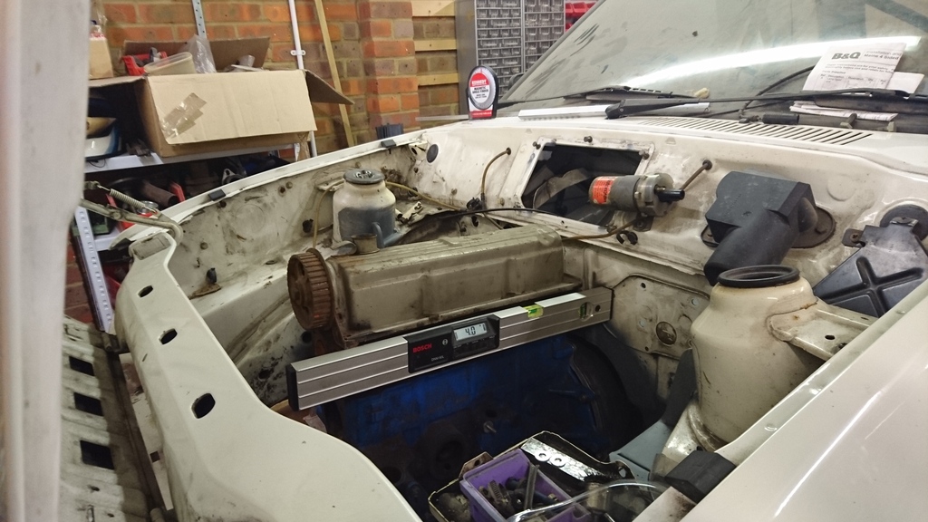
Dummy engine and gearbox back in. Now propped up to their final position (4 degrees as per rwd RS2000), I am about to embark on making the engine side of the engine mounts. Currently not sure how to tack the World Cup bush outer rings in the correct position without actually using the rubber bushes. Obviously, I want everything located in the right positions, but don't want to apply tons of heat into the bush. I know I could get some steel or aluminium dummies made up, but Is there an easy/quick alternative I haven't thought of?
That aside, hoping the engine and gearbox will be self supporting in a week.
20-11-2016, 07:13 PM
#57
Regular Contributor

Nice project, what about cutting a steel tube to size and welding washers to either end to mock up the bush, It don't need to be strong as your only using it as a reference?
love the fabrication
regards
Paul
love the fabrication
regards
Paul
13-01-2017, 08:17 AM
#58
I've now got the dummy engine and gearbox sitting back in the engine bay. Time to finish mounting the engine. So chocked it up to the right height and angle and made up the mounting brackets between the block and chassis mounts. I used part of a kit sourced from Alan Dent, but added some additional bracing top and bottom.
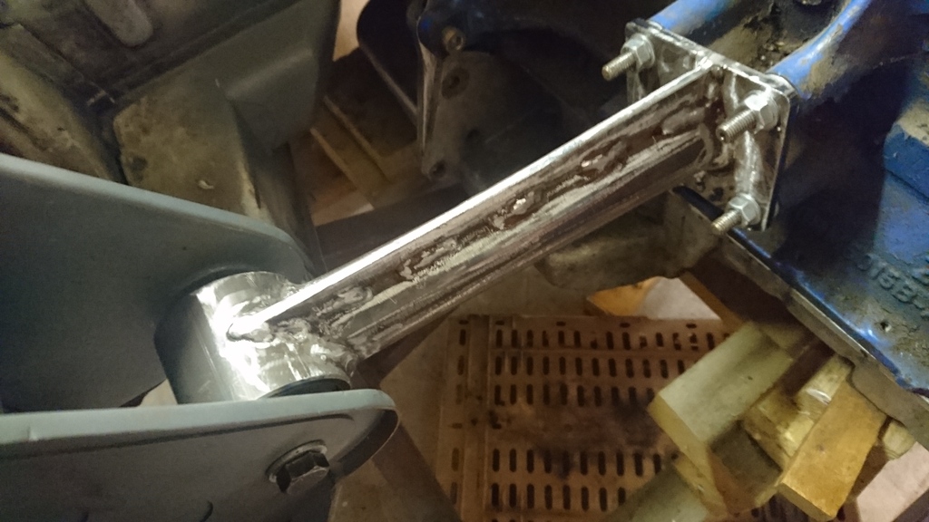
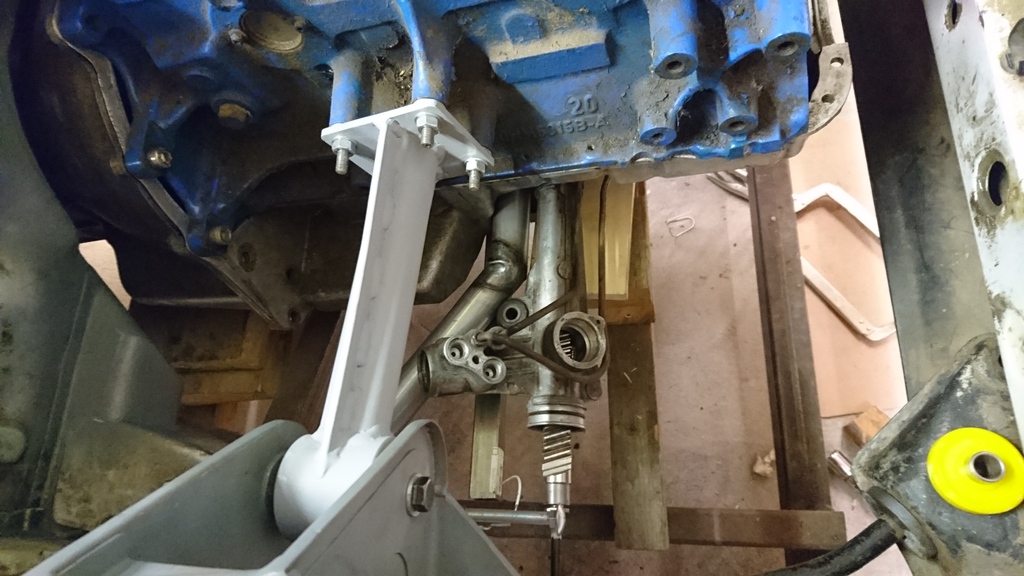
Gave the brackets a quick coat of primer once the bushes were pressed in and assembled with the special side spacers I had made up. I made a jig up to allow me to weld the various parts of the brackets together in situ without using the proper bushes and this worked well.
Once the engine was free and self supporting, I decided to position the steering rack. A problem! I originally thought that the centreline of the rack would be at the same height as the inner TCA mounts. This would be fine as I could space the steering arm mount down by the relevant amount, but out of best practice, I didn't want to go lower. I need at least half an inch clearance between the rack body and the sump. Maybe I could get the height and clearance with a manual rack, but I want to retain the power rack (particularly as I have put a lot of work into getting a 2WD Cosworth rack to work with a short 4x4 pinion- which I really need).
My new plan is to drop the inner track control arm mounts (and front tie bar mounts) by around 30mm. This I can easily do. More about that to come, but essentially I can engineer this into the steering rack support cross member. The big issue here is that the roll centre now drops too low. The angle of the TCA means that the front roll centre is disproportionate to the live axle with the panhard in the position I want to put it. There is a solution. New hubs. My Sapphire Cosworth hubs although a perfect fit will no longer work, so I have three choices; First- 3 door Cosworth hubs. Good geometry and I can used my shiny new 4 pot brakes, but these use a taper ball joint. I'm trying to find out if I can get some specials made up. Second- 4x4 Cosworth hubs with machined dummy CV joints fitted. Will fit my existing ball joint pin and I have some 4x4 Bilsteins kicking around, but I can't easily use the brakes I want to. May need to do some more digging here, but mot also sure the track or geometry will be the same as the Sapphire set up. Thirdly- Scorpio '95 hubs. I can get them to fit, but there will be several compromises. I can get the 3 door Cosworth brakes to fit, but these hubs are really big and chunky and the geometry is a totally unknown. But all three of these do have the correct lower ball joint mounting point to pull back the roll centre to where it should be . I just need to make a decision. Maybe try each to see which works best?
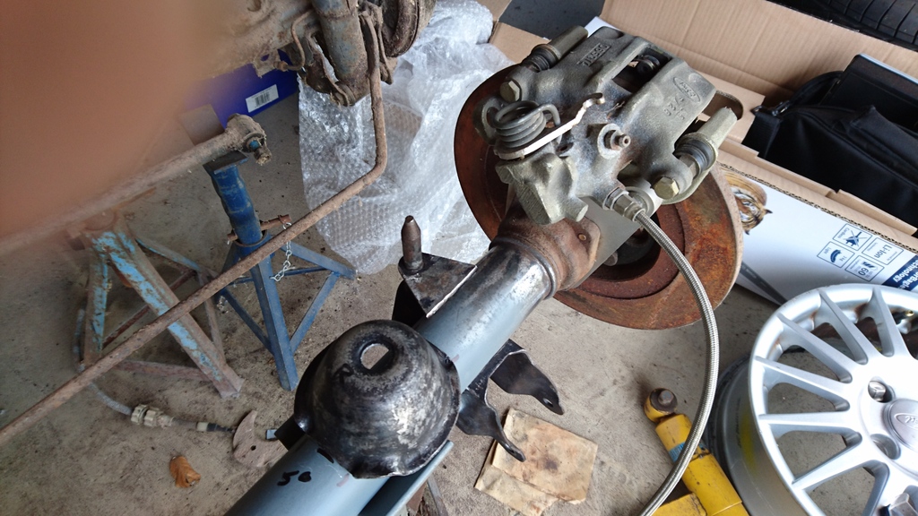
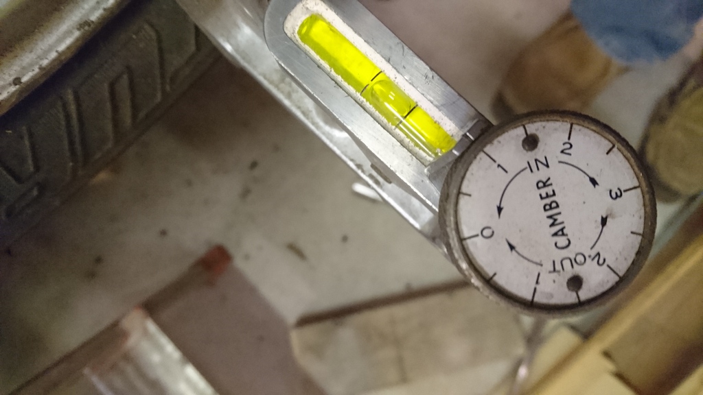
Anyway, I roughly assembled the front suspension together using the existing mounting points. Stuck a disc and a wheel on , jacked the suspension up to normal ride height and checked the camber. Just less than one degree. Just what I wanted. Good news, but disappointing, that I need to change the hub and this may change.
Next job. The steering rack cross member/support and revived suspension mounting points.
Sort hub choice
Modify track control arms to be adjustable.


Gave the brackets a quick coat of primer once the bushes were pressed in and assembled with the special side spacers I had made up. I made a jig up to allow me to weld the various parts of the brackets together in situ without using the proper bushes and this worked well.
Once the engine was free and self supporting, I decided to position the steering rack. A problem! I originally thought that the centreline of the rack would be at the same height as the inner TCA mounts. This would be fine as I could space the steering arm mount down by the relevant amount, but out of best practice, I didn't want to go lower. I need at least half an inch clearance between the rack body and the sump. Maybe I could get the height and clearance with a manual rack, but I want to retain the power rack (particularly as I have put a lot of work into getting a 2WD Cosworth rack to work with a short 4x4 pinion- which I really need).
My new plan is to drop the inner track control arm mounts (and front tie bar mounts) by around 30mm. This I can easily do. More about that to come, but essentially I can engineer this into the steering rack support cross member. The big issue here is that the roll centre now drops too low. The angle of the TCA means that the front roll centre is disproportionate to the live axle with the panhard in the position I want to put it. There is a solution. New hubs. My Sapphire Cosworth hubs although a perfect fit will no longer work, so I have three choices; First- 3 door Cosworth hubs. Good geometry and I can used my shiny new 4 pot brakes, but these use a taper ball joint. I'm trying to find out if I can get some specials made up. Second- 4x4 Cosworth hubs with machined dummy CV joints fitted. Will fit my existing ball joint pin and I have some 4x4 Bilsteins kicking around, but I can't easily use the brakes I want to. May need to do some more digging here, but mot also sure the track or geometry will be the same as the Sapphire set up. Thirdly- Scorpio '95 hubs. I can get them to fit, but there will be several compromises. I can get the 3 door Cosworth brakes to fit, but these hubs are really big and chunky and the geometry is a totally unknown. But all three of these do have the correct lower ball joint mounting point to pull back the roll centre to where it should be . I just need to make a decision. Maybe try each to see which works best?
Anyway, I roughly assembled the front suspension together using the existing mounting points. Stuck a disc and a wheel on , jacked the suspension up to normal ride height and checked the camber. Just less than one degree. Just what I wanted. Good news, but disappointing, that I need to change the hub and this may change.


Next job. The steering rack cross member/support and revived suspension mounting points.
Sort hub choice
Modify track control arms to be adjustable.
13-01-2017, 09:48 AM
#59
10K+ Poster!!
nice work, keep the updates coming.
When all the fabrication is finished will you strip it all apart and paint everything up?
When all the fabrication is finished will you strip it all apart and paint everything up?
13-01-2017, 10:39 AM
#60
Thanks for the comments.
Yes, the shell will be given a fresh coat of diamond white inside, underneath, etc. But I may cheat and leave the outside for the short term as it is very good. That way I'll be happier to give it some stick without fear of scraping it.
Yes, the shell will be given a fresh coat of diamond white inside, underneath, etc. But I may cheat and leave the outside for the short term as it is very good. That way I'll be happier to give it some stick without fear of scraping it.
13-01-2017, 10:47 AM
#61
10K+ Poster!!
Cool, sounds like a good plan. I cant wait to see this one finished.
18-01-2017, 11:29 AM
#62
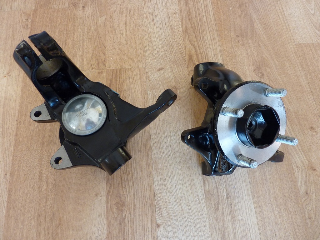
I have looked into the alternative hubs that I need in order to improve the roll centre issue I have and it now seems that the most ideal solution is the 3 door Cosworth hub.
The Scorpio part is just massive and the steering arms are just too long at 140mm length (considerably longer than Sierras). The 4x4 Cosworth hubs would be a straightforward fit and although the general wheel geometry is still a bit of an unknown, I have since discovered that all 4x4 Sierras have the steering rack positioned higher from the TCA mounts compared to the 2WD. The 2WD cars have the centre line of the rack about 25mm higher than the centreline of the inner TCA bolt holes. The 4x4 cars have a dimension of around 65mm and this increase is then reflected in the steering arm height on the hubs. Even with the 2WD hub I would need a small spacer to drop the TRE down slightly, but on the 4x4 hub, this would be a pretty big spacer (too much I think).
So the 3 door Cosworth Version it is, but it is not a simple swap over. My existing Sapphire Cosworth hubs fit to the bottom ball joint with a 17mm parallel pin and pinch bolt, but the 3 door uses a taper pin and lock nut. Currently my TCA and bottom ball joint are all standard(ish) Fiesta mark2 and give me good camber and castor figures. I want to keep this set up if possible, so I somehow need to engineer a solution to use a taper pin.
I don�t understand why the Sapphire Cosworth hubs do not have the same roll centre geometry as the 3 door. Understandable if the 4 door car sat higher than the 3 door, but from memory the standard Sapphire Cosworth seemed just as low; so puzzling!
That said, I need to ask a couple of questions:
Does anyone know of a company or have a contact that can modify/rebuild ball joints or replaces the old ball joint internals with a spherical bearing and new pin into the existing housing? I know something similar was done to standard Escort TCA�s a while ago. And they looked really good too but I don't know who modified them.
Does anyone have any 3 door Cosworth hubs for sale?
Hopefully someone can point me in the right direction.
In the meantime, loads to do, but first I can press on with my steering rack support cross member. I�d prefer to make it out of aluminium, but steel will have to do for now. As well as support the rack, it will also serve to reduce any flex from the inner TCA mounts. I�ve always had restrictions with the rack position. The height is a known issue but I still want to promote ideal Ackermann geometry, so the rack mounts will allow a certain amount of up/down and backwards/forwards adjustment. Fingers crossed it will be enough. I�ll post an image as soon as I have something meaningful to show.
22-01-2017, 08:56 AM
#63
10K+ Poster!!
Try prop shaft services near Hounslow if they don't do the driveshafts they will know someone who will
22-01-2017, 08:56 AM
#64
10K+ Poster!!
Speak to Kevin. 020 8844 2265
22-01-2017, 09:32 AM
#66
I could be persuaded to sell my 3 door hubs, but they owe me a lot of money and time !
They've been shot blasted, wire wheeled and epoxied, followed by 2 pack satin black.
New decent quality bearings from Matt Lewis Motorsport.
Surface ground hub faces to ensure the hubs run true to the bearings.
Genuine Ford new wheels studs.
Genuine Ford new grease caps.
Would want �475 for them
Hubs cost me �250
Wheel bearings are �75
Shot blasting �20
Wheel studs �20
Grease caps �50+ if you can find any..
Plus paint and time.
I'm considering making a set of aluminium and these might be surplus to requirements.

Thread
Thread Starter
Forum
Replies
Last Post
Focosmitch
Ford RS Cosworth Parts for Sale
36
09-10-2015 07:38 PM
borboyous
Cars for Sale
6
22-08-2015 11:17 AM