Want to learn about dyno power figure manipulation? Read on...
 18-07-2013, 06:19 AM
#161
Testing the future
thanks gents, i appreciate that my effort is appreciated  it's great that it's helped you Dojj, and hopefully it has helped others. i've tried to make it understandable which has meant that it seems very long winded, but hopefully by breaking it down like that it, the length is a help and not a hindrance.
this thread is like the good old days on here. where's AlexF when you need him?
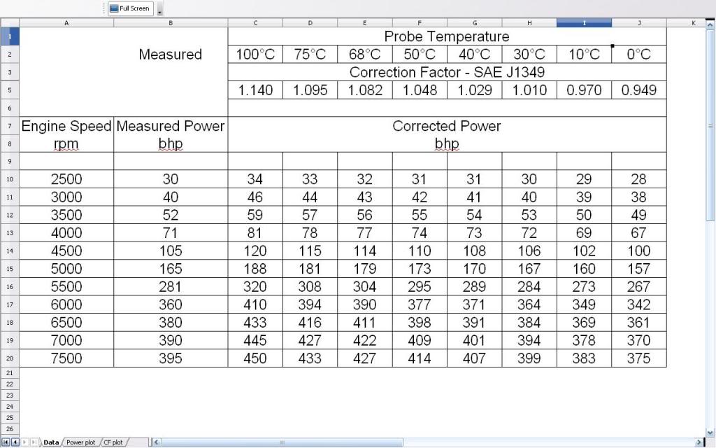
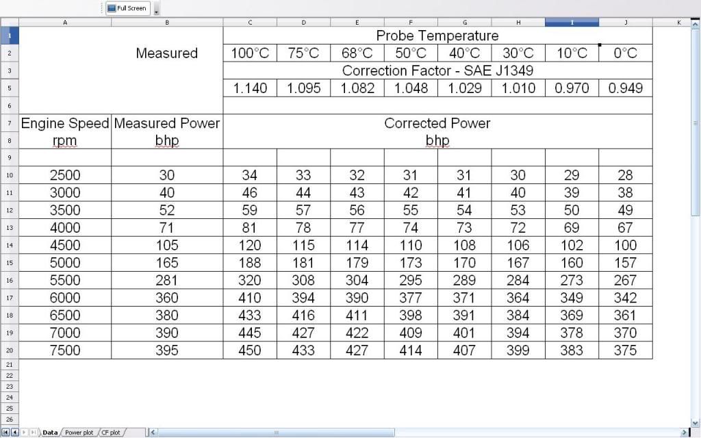
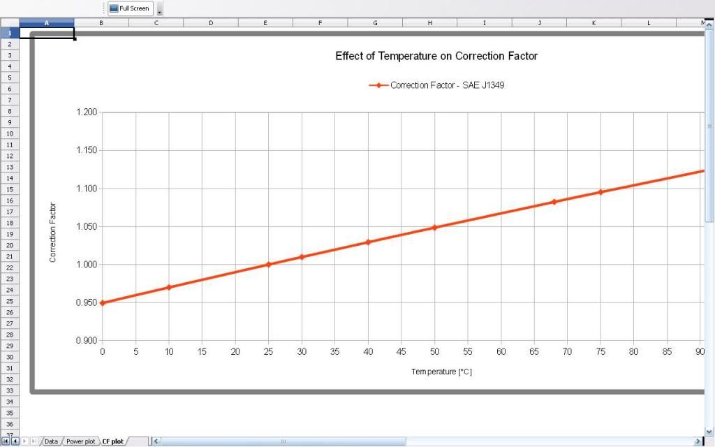
anyway, here's the data of the SAE J1349 Correction factor for temperature only. you could apply this to any measured power that you have had done at standard pressure of 990mbar:
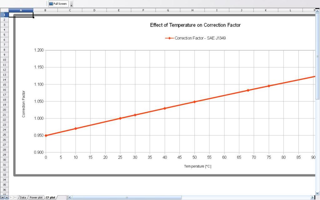
plotted as a chart so that you can easily get the CF for a temperature that is not in the table above
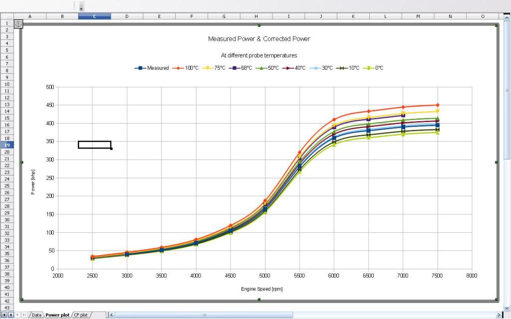
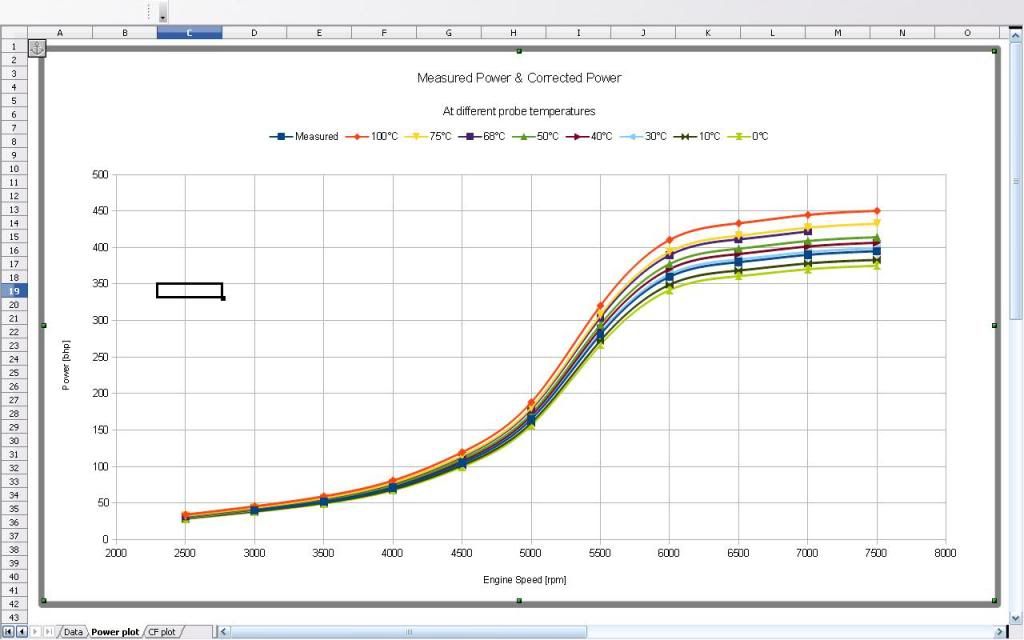
and lastly those correction factors applied to the original measured power at 26�C
now, what are the effects of keeping the temperature the same, but having a different pressure? are they greater or not? this is probably not as common a situation to happen as the incorrect positioning of the temperature probe, but an incorrectly reading pressure sensor would need to read low in order to give a higher corrected power (as it is on the bottom line of the calculation) and to give the same CF as a temperature of 100�C it would need to be 885mbar.
if the measured pressure is not shown on your printout, who knows what it might be reading and correcting to? something to be aware of.
as stu has mentioned, a lot of dyno cells don't have the same pressure inside as the atmosphere outside (which changes with the weather anyway) as they tend to either have fan setups installed that are either blowing air in (and making them a higher pressure, like a bouncy castle) or sucking air out (and making them a lower pressure) so the engine being tested sees that different pressure as well as the sensor being used for the correction factor calculation and so the measured power will already be higher or lower than it would have at standard atmospheric pressure of 990mbar. In that case, as long as the pressure and temperature probes are accurately reading the pressure and intake air temperature that the engine is consuming, then possibly the correction factor can be reasonably applied.
it's great that it's helped you Dojj, and hopefully it has helped others. i've tried to make it understandable which has meant that it seems very long winded, but hopefully by breaking it down like that it, the length is a help and not a hindrance.this thread is like the good old days on here. where's AlexF when you need him?
anyway, here's the data of the SAE J1349 Correction factor for temperature only. you could apply this to any measured power that you have had done at standard pressure of 990mbar:
plotted as a chart so that you can easily get the CF for a temperature that is not in the table above
and lastly those correction factors applied to the original measured power at 26�C
now, what are the effects of keeping the temperature the same, but having a different pressure? are they greater or not? this is probably not as common a situation to happen as the incorrect positioning of the temperature probe, but an incorrectly reading pressure sensor would need to read low in order to give a higher corrected power (as it is on the bottom line of the calculation) and to give the same CF as a temperature of 100�C it would need to be 885mbar.
if the measured pressure is not shown on your printout, who knows what it might be reading and correcting to? something to be aware of.
as stu has mentioned, a lot of dyno cells don't have the same pressure inside as the atmosphere outside (which changes with the weather anyway) as they tend to either have fan setups installed that are either blowing air in (and making them a higher pressure, like a bouncy castle) or sucking air out (and making them a lower pressure) so the engine being tested sees that different pressure as well as the sensor being used for the correction factor calculation and so the measured power will already be higher or lower than it would have at standard atmospheric pressure of 990mbar. In that case, as long as the pressure and temperature probes are accurately reading the pressure and intake air temperature that the engine is consuming, then possibly the correction factor can be reasonably applied.
Last edited by foreigneRS; 18-07-2013 at 06:37 AM.
 18-07-2013, 06:34 AM
#162
10K+ Poster!!
iTrader: (4)
thanks gents, i appreciate that my effort is appreciated it's great that it's helped you Dojj, and hopefully it has helped others. i've tried to make it understandable which has meant that it seems very long winded, but hopefully by breaking it down like that it, the length is a help and not a hindrance.
this thread is like the good old days on here. where's AlexF when you need him?
anyway, here's the data of the SAE J1349 Correction factor for temperature only. you could apply this to any measured power that you have had done at standard pressure of 990mbar:
plotted as a chart so that you can easily get the CF for a temperature that is not in the table above
and lastly those correction factors applied to the original measured power at 26�C
now, what are the effects of keeping the temperature the same, but having a different pressure? are they greater or not?
it's great that it's helped you Dojj, and hopefully it has helped others. i've tried to make it understandable which has meant that it seems very long winded, but hopefully by breaking it down like that it, the length is a help and not a hindrance.this thread is like the good old days on here. where's AlexF when you need him?
anyway, here's the data of the SAE J1349 Correction factor for temperature only. you could apply this to any measured power that you have had done at standard pressure of 990mbar:
plotted as a chart so that you can easily get the CF for a temperature that is not in the table above
and lastly those correction factors applied to the original measured power at 26�C
now, what are the effects of keeping the temperature the same, but having a different pressure? are they greater or not?
that is absolutely brilliant thank you, exactly what I wanted to see in a way that makes sense without confuseing me
 18-07-2013, 06:43 AM
#163
10K+ Poster!!
iTrader: (4)
right, quick lash up of some data
the Correction Factor should be calculated according to SAE J1349 as:
Correction Factor = 1.180 [ ( 990/Pd) x (( Tc + 273)/(298)) ^ 0.5 ] - 0.18
where Pd is the atmospheric pressure that the measued power was taken at (in mbar) and Tc is the temperature at which the power was measured at in degrees Celcius (�C)
Now, that might look complicated, but if we break it down we can understand it easier.
Let's put the numbers in for our pretend situation where we have done a power run at the standard conditions of 990mbar and 25�C but want to see what effect putting the dyno temperature probe used for compensation (that should be placed in the intake air stream) in a hot area under the bonnet that is at 100�C but at the same standard atmospheric pressure (so that we eliminate the effect of air pressure compensation and only look at temperature compensation):
Correction Factor = 1.180 [ ( 990/990) x (( 100 + 273)/(298)) ^ 0.5 ] - 0.18
the bit where the temperature goes has 273 added to it and is divided by 298 as it needs to be in absolute temperature as measured in Kelvin where 0�C = 273K (the 298 is the standard temperature of 25 + 273 = 298K)
by keeping the same atmospheric conditions, the 990/990 is just a multiplication of 1, so makes no difference
our equation can then be further simplified by doing the maths in stages so it could look like this next:
Correction Factor = 1.180 [ (1) x ((373)/298) ^ 0.5 ] - 0.18
then
Correction Factor = 1.180 [ ((373)/298) ^ 0.5 ] - 0.18
then
Correction Factor = 1.180 [ 1.25 ^ 0.5 ] - 0.18
the ^ symbol means 'to the power of'. if something is to the power of 2 it is squared, 3 is cubed etc, so to the power of 0.5 is the square root. it's just a way of writing it in simple text form where it's not convenient to use the square root symbol that you may be familiar with, the √
further simplification gives us
Correction Factor = 1.180 [ 1.11878 ] - 0.18 or
Correction Factor = 1.180 * 1.11878 - 0.18
and then
Correction Factor = 1.32 - 0.18
and finally
Correction Factor = 1.14
What this means is that if you do a power run at 25�C but have the temperature correction probe in an area that is 100�C, the measured power would get multiplied by 1.14 to give the corrected power.
in the case of the cossie that Stu shows an example of, where the measured power was at 26�C (which is close enough to the standard 25�C to make no difference, 1bhp), if a 100�C cheat were used, the measured power of 395bhp @ 7500rpm would give a corrected power of 395 * 1.14 = 450bhp
using the example that Stu has above, when the probe is at 68�C, the Correction Factor calculates out at 1.082 and 395 * 1.082 = 427bhp as his plot also shows. this proves my point that you don't need to do the actual run with the probe in the cup of tea to give you the data that you want
you can plug any temperature you like into the formula to give you the correction factor. i have done that for a range of temperatures between 0�C and 100�C and applied them to the data from the measured run above and plotted the corrected power figures that they would give. i'll post that up later when i figure out how to get the charts as a graphic (i'm using a new to me openoffice spreadsheet program, not the ms excel that i'm used to )
)
the Correction Factor should be calculated according to SAE J1349 as:
Correction Factor = 1.180 [ ( 990/Pd) x (( Tc + 273)/(298)) ^ 0.5 ] - 0.18
where Pd is the atmospheric pressure that the measued power was taken at (in mbar) and Tc is the temperature at which the power was measured at in degrees Celcius (�C)
Now, that might look complicated, but if we break it down we can understand it easier.
Let's put the numbers in for our pretend situation where we have done a power run at the standard conditions of 990mbar and 25�C but want to see what effect putting the dyno temperature probe used for compensation (that should be placed in the intake air stream) in a hot area under the bonnet that is at 100�C but at the same standard atmospheric pressure (so that we eliminate the effect of air pressure compensation and only look at temperature compensation):
Correction Factor = 1.180 [ ( 990/990) x (( 100 + 273)/(298)) ^ 0.5 ] - 0.18
the bit where the temperature goes has 273 added to it and is divided by 298 as it needs to be in absolute temperature as measured in Kelvin where 0�C = 273K (the 298 is the standard temperature of 25 + 273 = 298K)
by keeping the same atmospheric conditions, the 990/990 is just a multiplication of 1, so makes no difference
our equation can then be further simplified by doing the maths in stages so it could look like this next:
Correction Factor = 1.180 [ (1) x ((373)/298) ^ 0.5 ] - 0.18
then
Correction Factor = 1.180 [ ((373)/298) ^ 0.5 ] - 0.18
then
Correction Factor = 1.180 [ 1.25 ^ 0.5 ] - 0.18
the ^ symbol means 'to the power of'. if something is to the power of 2 it is squared, 3 is cubed etc, so to the power of 0.5 is the square root. it's just a way of writing it in simple text form where it's not convenient to use the square root symbol that you may be familiar with, the √
further simplification gives us
Correction Factor = 1.180 [ 1.11878 ] - 0.18 or
Correction Factor = 1.180 * 1.11878 - 0.18
and then
Correction Factor = 1.32 - 0.18
and finally
Correction Factor = 1.14
What this means is that if you do a power run at 25�C but have the temperature correction probe in an area that is 100�C, the measured power would get multiplied by 1.14 to give the corrected power.
in the case of the cossie that Stu shows an example of, where the measured power was at 26�C (which is close enough to the standard 25�C to make no difference, 1bhp), if a 100�C cheat were used, the measured power of 395bhp @ 7500rpm would give a corrected power of 395 * 1.14 = 450bhp
using the example that Stu has above, when the probe is at 68�C, the Correction Factor calculates out at 1.082 and 395 * 1.082 = 427bhp as his plot also shows. this proves my point that you don't need to do the actual run with the probe in the cup of tea to give you the data that you want
you can plug any temperature you like into the formula to give you the correction factor. i have done that for a range of temperatures between 0�C and 100�C and applied them to the data from the measured run above and plotted the corrected power figures that they would give. i'll post that up later when i figure out how to get the charts as a graphic (i'm using a new to me openoffice spreadsheet program, not the ms excel that i'm used to
thank you this should help me understand it once ive read it a few more times
you certainly have a far more academic mind than me fair play

ive gotta do the wages now but when I get time later I am gonna try and do the calculation myself for the 100c run ( ive put the c in look
we definatly got of on the wrong foot but at least were on the same page now, thank you, its very much appreciated
 18-07-2013, 09:05 AM
#165
That is indeed true, it calculates the expected loss of rotating the rear roller. However, the correct way to run them varies, because a powerful car needs to climb the roller to get full traction as the vehicles weight starts to bear down on the roller centre line the more it climbs and with very high horsepower stuff you will never get traction without letting it climb so the only thing you can do is make sure that any tuning done the car climbs the same amount by correct installation and tension of the "Jesus straps"
Engine dyno instead gives very accurate measurement in terms pf no drivetrain guesses but thats offset by ending up with the fact its not installed in the bay with the airfilter and intercooler located accordingly and so doesnt really simulate the real world environment of the engine in the car, so still very flawed.
The bolt to hub ones are one way to maintain very repeatable results and consistant losses, and still have the engine installed in the bay, so on paper at least look the most sensible option. Bit of a pain to use though, espeically when you just want a quick power run.
As I know that you will have looked into things very thoroughly, I would be interested to hear why you dismissed the bolt to hub type in favour of rollers?
Was it just down to the logistics of getting cars on and off?
18-07-2013, 09:48 AM
#167


On top of that, I love the new software capabilities of this new DD model, it far surpasses the old one and anything else I had a rep bring me. It really is pretty damn good.
Should be better as of tonight too, as I have a knew knock monitoring system arriving today that will allow me to both monitor, and datalog knock output on the 52" screens and it will tie into the dyno software in a few months so I can even graph it live.
18-07-2013, 10:18 AM
#168
Purely that mate, I just don't want to be taking wheels on and off as I only see the hub dynos as a benefit for silly power cars. We regularly do up to and over 500bhp and just don't have problems with traction using the HP traction tie down blocks. Bigger power turbocharged cars, yes, definitely an issue regardless of what the dyno manufacturers may try to tell us, but we don't do enough of them in the real world to care about that problem.
Also, tyres having a bit of give, or even being able to slip very slightly during a shock load, is no bad thing for the cars transmisison of course!
I bet for example if you rod the block and lock the engine solid on a hub dyno it very often takes the transmission with it too, and thats a really bad day for the customer, lol.
On top of that, I love the new software capabilities of this new DD model, it far surpasses the old one and anything else I had a rep bring me. It really is pretty damn good.
Should be better as of tonight too, as I have a knew knock monitoring system arriving today that will allow me to both monitor, and datalog knock output on the 52" screens and it will tie into the dyno software in a few months so I can even graph it live. 
Last edited by Chip; 18-07-2013 at 10:20 AM.
18-07-2013, 10:25 AM
#169
Yes considering its essentially a "lower" model in the range, it seems to actually be a lot more capable, I guess just cause its the latest version, like a modern fiesta is so much better a car than an old granada, lol.
Thankfully, they don't break often though.
Being digital now, It also has none of the delays of older models when your trying to load it up or change hold speeds etc. I can go from 10 - 50% load in under 1 second, something a lot of the old ones struggle with in my experience.
Sounds good, although Im guessing despite that you will still rely on sound too?
Last edited by Stu @ M Developments; 18-07-2013 at 10:26 AM.
18-07-2013, 10:32 AM
#170
God yeah - but you cant beat data for proving to a customer the reason they just spun a bottom end on their home built engine is that the oil pump cosworth remade was faulty or they built something wrong rather than we introduced det like they might otherwise claim if we couldnt prove categorically with logs that we didnt
18-07-2013, 11:10 AM
#172
PassionFord Post Troll
No, far from it.
The more you strap it down the more is lost through frictional losses is the bearings and, more importantly, tyre deflection.
When you add weight you alter the tyres shape, and to deflect the sidewall and tread of a tyre takes power. As well as that, the tacho can end up out as well if you use the rollers as a tacho because under load the tyre is a different size than it is off load. Another error many dyno operators make as they don't set the tacho under load. It should really be done at peak torque with full load.
Tyre pressures cause a similar problem as the tyres heat up, the rolling circumference changes a little, as does the effective strapping tension.
If I ever own something I want put on the rollers, I think I'll be paying to travel too!
Best thread on here in a long old time.
Thanks to all for explaining it simply enough for us mere mortals!
 18-07-2013, 07:28 PM
#174
you cant fix stupid
Trouble with removing temp correction would be if you ran on a day when its 5 degrees you would get a massive over reading as a result as you would be stopping the dyno from correcting the temp downwards.
The way to get an accurate figure is just to use it properly with the right temp for correction. Which I'm sure is what MSD do.
The way to get an accurate figure is just to use it properly with the right temp for correction. Which I'm sure is what MSD do.
id rather go in on a hot day and see less bhp but know its what it really made in that weather condition not what a computer and operator can fudge it up to.
am i making sense cos im finding it hard to explain sorry
18-07-2013, 07:57 PM
#175
Testing the future
cheers for reply but im still confused. how do i just get a figure of what the car makes on any given day with whatever temp it is. i know colder is more bhp and hotter less but this correction thing seems like rolling roads can fake my result.
id rather go in on a hot day and see less bhp but know its what it really made in that weather condition not what a computer and operator can fudge it up to.
am i making sense cos im finding it hard to explain sorry
id rather go in on a hot day and see less bhp but know its what it really made in that weather condition not what a computer and operator can fudge it up to.
am i making sense cos im finding it hard to explain sorry
i wouldn't quite agree with chip saying it would massively over read - the correction factor at 5degC as you can see from my plot above is 0.96, so a 100bhp measured at 5 degC should be compared with a corrected (100 x 0.96) = 96bhp which is what you would expect to measure at 25degC or a 5 degC measured 500bhp should be compared to the 480bhp that you would expect to measure at 25degC - so not a massive difference, but a significant difference nevertheless
however, it's been a while since i worked to the SAE guidelines, but i believe that they say that the correction factor is not valid if you have to correct for more than 3% difference in pressure or temperature or a combination of greater than 6% of both or something along those lines, so you can't expect the correction factor to be close all of the time - especially with turbocharged engines that have different effects on their volumetric efficiency from such things than a N/A engine does
Last edited by foreigneRS; 18-07-2013 at 08:15 PM.
18-07-2013, 08:32 PM
#176
you cant fix stupid
you get the measured (uncorrected) data - as simple as that. any session you have, you should ask for both the uncorrected data and any corrected data should have the pressure and temperature used for correction and what correction standard was used. without all of those things, the data doesn't mean much
i wouldn't quite agree with chip saying it would massively over read - the correction factor at 5degC as you can see from my plot above is 0.96, so a 100bhp measured at 5 degC should be compared with a corrected (100 x 0.96) = 96bhp which is what you would expect to measure at 25degC or a 5 degC measured 500bhp should be compared to the 480bhp that you would expect to measure at 25degC - so not a massive difference, but a significant difference nevertheless
however, it's been a while since i worked to the SAE guidelines, but i believe that they say that the correction factor is not valid if you have to correct for more than 3% difference in pressure or temperature or a combination of greater than 6% of both or something along those lines, so you can't expect the correction factor to be close all of the time - especially with turbocharged engines that have different effects on their volumetric efficiency from such things than a N/A engine does
thank you that makes sense
19-07-2013, 05:19 AM
#177
cheers for reply but im still confused. how do i just get a figure of what the car makes on any given day with whatever temp it is. i know colder is more bhp and hotter less but this correction thing seems like rolling roads can fake my result.
id rather go in on a hot day and see less bhp but know its what it really made in that weather condition not what a computer and operator can fudge it up to.
am i making sense cos im finding it hard to explain sorry
However, bear in mind that its not "fudged" data, it's the same data everyone in the world uses to measure power. If you brought her to me on 35c roasting hot day and I forgot to turn the inlet fans on so the atmos was down at low 900s and she made 300bhp - what are you going to compare that information to? Because in those conditions, no car in the world would have made quoted power either, they would all have been well down and in reality, you engine really does have more power.
That's why correction exists - so we all have a baseline at known temperatures and pressures.
Put another way - what would stop me pressurising my cell with the 20'000cfm intake fan and leaving the rest of the cell closed so the pressure stayed high while I did a quick run and effectively "turbocharged" your nasp engine" before I gave you your tuning bill? The uncorrected data in this case would send you down the wrong path thinking you had far more power than you had unless you knew how to interpret the data, which is what this topics all about. Educating the petrol head.
Last edited by Stu @ M Developments; 19-07-2013 at 05:22 AM.
19-07-2013, 05:30 AM
#178
Testing the future
i've been thinking about the pressurised cell thing and i'm not convinced that it would have any effect as the paths to both the inlet and the exhaust are still at the same pressure. where it would have an effect would be if pressurised air was ducted to the inlet but the exhaust was into atmospheric pressure (or ducted to forced extraction) where you would create a positive pressure difference (effectively supercharging it as you say)
19-07-2013, 05:49 AM
#179
i've been thinking about the pressurised cell thing and i'm not convinced that it would have any effect as the paths to both the inlet and the exhaust are still at the same pressure. where it would have an effect would be if pressurised air was ducted to the inlet but the exhaust was into atmospheric pressure (or ducted to forced extraction) where you would create a positive pressure difference (effectively supercharging it as you say)
The question is, will the engine make more power from the extra oxygen we force into the cylinders than it loses through the pumping losses due to the higher atmosphere acting on the exhaust outlet. I think it would, and If I wasnt worried about damaging my cell I would actually try it and find out for sure! In fact, I still might, just not with a customers car inside it - I would have to use my own. LOL
19-07-2013, 09:10 AM
#180
so does that mean that nick's "uncorrected vs corrected data" arguement is therefore not valid?
if you don't have ALL the data for the run you've just done then, as you say, you can' compare it to anything else so there would still be that "fudge" factor
and, while we are talking about rolling roads and power figures, are we still talking about wheel horespower or tyre horsepower? you made the seperation between the 2 earlier on stu in climbing out of the rollers etc, but can there be "that" much difference between 2 sets of figures? i'm assuming that the wheel hp would be measured using a hub duno and the tyre hp would be at the correctly loaded and pressurised tyres here and not comlicating things by introducing things like how to work out flywheel power, when you are running an auto box, and it's a hot day, and the cooler is trying too hard, and you've got to hold it in 2nd gear or anything like that
19-07-2013, 09:26 AM
#181
if you don't have ALL the data for the run you've just done then, as you say,
you can' compare it to anything else so there would still be that "fudge" factor
you can' compare it to anything else so there would still be that "fudge" factor
The same goes for "corrected data" unless you know what corrections were in place, your figures aren't of great use anywhere except the pub.
Maybe this video will illustrate it a little better.
Its a Focus RS Mk1 I live mapped this week on its O.E Ford ECU.
Is this power right, or wrong? And if you cant tell, do you know yet what data you need to get from me to find out? (The aim of this topic is to have you know the answer to this question by now)
(Fans of glowing exhaust manifolds will like this video.
Last edited by Stu @ M Developments; 19-07-2013 at 09:32 AM.
19-07-2013, 09:31 AM
#182
and, while we are talking about rolling roads and power figures, are we still
talking about wheel horespower or tyre horsepower? you made the seperation
between the 2 earlier on stu in climbing out of the rollers etc, but can there
be "that" much difference between 2 sets of figures? i'm assuming that the wheel
hp would be measured using a hub duno and the tyre hp would be at the correctly
loaded and pressurised tyres here
Rolling roads measure power at the tyres and to a small extent, tyre pressures can affect the readings as can the amount of strapping load applied to the tyre.
You should always put your tyres up to motorway full load pressures before a dyno run if possible as the higher they are the less they alter with load and temperature. DD Recommend 50psi + for sustained mapping.
19-07-2013, 04:12 PM
#184
PassionFord Post Whore!!

i've been thinking about the pressurised cell thing and i'm not convinced that it would have any effect as the paths to both the inlet and the exhaust are still at the same pressure. where it would have an effect would be if pressurised air was ducted to the inlet but the exhaust was into atmospheric pressure (or ducted to forced extraction) where you would create a positive pressure difference (effectively supercharging it as you say)
we have positive and negative pressure engine test cells (2 different design applications) and the effect on engine performance is negligible (we correct for it, of course) but its pretty insignificant when you compare it to the correction factor for temperature.
19-07-2013, 05:07 PM
#185
Testing the future
the only way that the exhaust could be at a lower pressure than the inlet is if it were ducted to the exhaust extract, which it doesn't look like it is in Stu's setup.
as i said earlier in the thread, the CF for pressure difference is much smaller than the CF for temperature difference over the range of atmospheric conditions that you can expect from day to day, but there is the potential to create them with a badly designed ventilation system or by falsifying or having a faulty or out of calibration sensor.
19-07-2013, 05:14 PM
#186
Maybe this video will illustrate it a little better.
Its a Focus RS Mk1 I live mapped this week on its O.E Ford ECU.
Is this power right, or wrong? And if you cant tell, do you know yet what data you need to get from me to find out? (The aim of this topic is to have you know the answer to this question by now)
http://youtu.be/nIfRjNYJn9E
(Fans of glowing exhaust manifolds will like this video. )
Its a Focus RS Mk1 I live mapped this week on its O.E Ford ECU.
Is this power right, or wrong? And if you cant tell, do you know yet what data you need to get from me to find out? (The aim of this topic is to have you know the answer to this question by now)
http://youtu.be/nIfRjNYJn9E
(Fans of glowing exhaust manifolds will like this video.
19-07-2013, 05:18 PM
#187
Testing the future
19-07-2013, 05:24 PM
#188
Check it's realistic, if it was in a cup of tea for example (I know that was the intake probe in Stu's example) it would read far more humid than it is and inflate the correction factor wouldn't it?
I have never operated a dyno by the way, just trying to learn.
I have never operated a dyno by the way, just trying to learn.
19-07-2013, 05:26 PM
#189
10K+ Poster!!
iTrader: (4)
thanks gents, i appreciate that my effort is appreciated it's great that it's helped you Dojj, and hopefully it has helped others. i've tried to make it understandable which has meant that it seems very long winded, but hopefully by breaking it down like that it, the length is a help and not a hindrance.
this thread is like the good old days on here. where's AlexF when you need him?
anyway, here's the data of the SAE J1349 Correction factor for temperature only. you could apply this to any measured power that you have had done at standard pressure of 990mbar:
plotted as a chart so that you can easily get the CF for a temperature that is not in the table above
and lastly those correction factors applied to the original measured power at 26�C
now, what are the effects of keeping the temperature the same, but having a different pressure? are they greater or not? this is probably not as common a situation to happen as the incorrect positioning of the temperature probe, but an incorrectly reading pressure sensor would need to read low in order to give a higher corrected power (as it is on the bottom line of the calculation) and to give the same CF as a temperature of 100�C it would need to be 885mbar.
if the measured pressure is not shown on your printout, who knows what it might be reading and correcting to? something to be aware of.
as stu has mentioned, a lot of dyno cells don't have the same pressure inside as the atmosphere outside (which changes with the weather anyway) as they tend to either have fan setups installed that are either blowing air in (and making them a higher pressure, like a bouncy castle) or sucking air out (and making them a lower pressure) so the engine being tested sees that different pressure as well as the sensor being used for the correction factor calculation and so the measured power will already be higher or lower than it would have at standard atmospheric pressure of 990mbar. In that case, as long as the pressure and temperature probes are accurately reading the pressure and intake air temperature that the engine is consuming, then possibly the correction factor can be reasonably applied.
it's great that it's helped you Dojj, and hopefully it has helped others. i've tried to make it understandable which has meant that it seems very long winded, but hopefully by breaking it down like that it, the length is a help and not a hindrance.this thread is like the good old days on here. where's AlexF when you need him?
anyway, here's the data of the SAE J1349 Correction factor for temperature only. you could apply this to any measured power that you have had done at standard pressure of 990mbar:
plotted as a chart so that you can easily get the CF for a temperature that is not in the table above
and lastly those correction factors applied to the original measured power at 26�C
now, what are the effects of keeping the temperature the same, but having a different pressure? are they greater or not? this is probably not as common a situation to happen as the incorrect positioning of the temperature probe, but an incorrectly reading pressure sensor would need to read low in order to give a higher corrected power (as it is on the bottom line of the calculation) and to give the same CF as a temperature of 100�C it would need to be 885mbar.
if the measured pressure is not shown on your printout, who knows what it might be reading and correcting to? something to be aware of.
as stu has mentioned, a lot of dyno cells don't have the same pressure inside as the atmosphere outside (which changes with the weather anyway) as they tend to either have fan setups installed that are either blowing air in (and making them a higher pressure, like a bouncy castle) or sucking air out (and making them a lower pressure) so the engine being tested sees that different pressure as well as the sensor being used for the correction factor calculation and so the measured power will already be higher or lower than it would have at standard atmospheric pressure of 990mbar. In that case, as long as the pressure and temperature probes are accurately reading the pressure and intake air temperature that the engine is consuming, then possibly the correction factor can be reasonably applied.
I can see it may make a small difference but wouldn't the turbo kind of offset a lot of that as its sucking and ramming it in the inlet ?
19-07-2013, 05:45 PM
#191
PassionFord Post Whore!!
surely the exhaust system would be ducted? otherwise he is filling the test cell with gas?
19-07-2013, 06:26 PM
#192
Advanced PassionFord User

Also, two points about the whole SAE thing, it's based on the ambient temperature and there are 2 SAE correction values, one which is simply called SAE and another which is SAE J1394? These obviously vary massively judging by Stu's findings
19-07-2013, 06:43 PM
#193
10K+ Poster!!
iTrader: (4)
It could make a difference with the pr on the compressor
Also, two points about the whole SAE thing, it's based on the ambient temperature and there are 2 SAE correction values, one which is simply called SAE and another which is SAE J1394? These obviously vary massively judging by Stu's findings
Also, two points about the whole SAE thing, it's based on the ambient temperature and there are 2 SAE correction values, one which is simply called SAE and another which is SAE J1394? These obviously vary massively judging by Stu's findings
19-07-2013, 07:03 PM
#194
Testing the future
not necessarily. there can be an exchange of air in the cell room much as you have an extractor fan in your bathroom (although a balanced system would also put fresh air into the room as well as extract out) and you don't pipe that directly up to your arsehole do you?
19-07-2013, 07:08 PM
#195
the humidity probe is probably not the same physical unit asthe temperature probe that might be in the cup of tea. but checking that it is realistic is definitely a good idea. I wasn't saying you wouldn't do anything with it, i was just asking.
not necessarily. there can be an exchange of air in the cell room much as you have an extractor fan in your bathroom (although a balanced system would also put fresh air into the room as well as extract out) and you don't pipe that directly up to your arsehole do you?
not necessarily. there can be an exchange of air in the cell room much as you have an extractor fan in your bathroom (although a balanced system would also put fresh air into the room as well as extract out) and you don't pipe that directly up to your arsehole do you?
20-07-2013, 02:04 PM
#196
You can see the collectors better here:

And the ducting itself here.
There is one either side of the cell and its ported out through fans and then through external silencers and out through a chimney above the building.

Interestingly, that's another place where some mappers cock up.
Your can't map a car properly with those collectors installed right up to the tailpipe as it screws up the fuel map
Last edited by Stu @ M Developments; 20-07-2013 at 02:16 PM.
20-07-2013, 02:54 PM
#197
PassionFord Post Whore!!
Stu, this would be for a totally different thread but.....
Could we have a nice thread as to why you can put a standard car (200bhp for a nice round figure) and be mapped to make more power with no mods etc. both NA and charged engines? And why?
Proper love how these subjects are written by you so I can understand them.
Could we have a nice thread as to why you can put a standard car (200bhp for a nice round figure) and be mapped to make more power with no mods etc. both NA and charged engines? And why?
Proper love how these subjects are written by you so I can understand them.
20-07-2013, 10:14 PM
#198
Stu, this would be for a totally different thread but.....
Could we have a nice thread as to why you can put a standard car (200bhp for a nice round figure) and be mapped to make more power with no mods etc. both NA and charged engines? And why?
Proper love how these subjects are written by you so I can understand them.
Could we have a nice thread as to why you can put a standard car (200bhp for a nice round figure) and be mapped to make more power with no mods etc. both NA and charged engines? And why?
Proper love how these subjects are written by you so I can understand them.
In the case of a turbo that's a case of the biggest gains will be from upping the boost and remove the reliability compromise.
Then for turbo and n/a you can introduce some tweaks to add some extra ignition and remove safety margin allowing for poor quality fuel etc.
Gains on diesels are the best, as the compromise you remove is largely emissions which customers don't care about.
Some n/a petrol cars (Clio 172 for example) run lean at full throttle in the midrange for emissions and Economy so see reasonable gains at that point if you richen them up a touch.
Most petrol turbo cars are too rich on boost to drop egt's so leaning them up can yield gains.
22-07-2013, 11:47 AM
#200
.

Join Date: Sep 2007
Location: Gloucestershire
Posts: 111
Likes: 0
Received 0 Likes
on
0 Posts
SO easy to fake bench dyno numbers, easier than a rolling road even.
In fact I'd say that's why some people pay the extra for dyno tuning.
I'm 100% some people on this forum will have had this convo with a bench dyno owner...
"How much power do you want it to make?"
"We will see, it'd be nice if it made over 600 though"
"No really, how much power do you want it to make?"
"Oh I see, 600+ please"
"No problem" (twiddles a few knobs, taps a few keys, hey presto)