Im sorry chaps, didnt realise i had replies!!
Thanks for your comments!!
Dont let the switches alarm you lol.. All the primary functions, such as the wing, fuel, ALS .etc are located on the main panel in the upper dash. The most switches are located in the lower dash panel.
I designed all the systems to have an "Auto" setting, so there is technically no need for the driver to make any changes. The reason for all the switches is just in case of a malfunction or a software glitch, and for example the cooling system needs overriding.
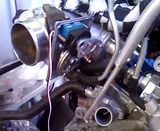
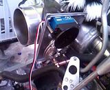
Ive made a little more progress.. I redesigned the drive by wire computer.. I finished it but excess noise was causing jitter, which I deemed unsafe.. I redesigned the system and implemented a suggestion to add a small amount of built in jitter - to prevent sticktion..
The new system utilises a secondary CPU with built in error checking using the original TPS. There is now an RS232 datalink between the two CPUs so there is absolutely no chance of noise.
Here is a little video;
Here is a short video where i used my function generator to emulate 0 - 100 - 0% throttle repeatedly for an hour. This simply tested the longevity of the PSU and servo.
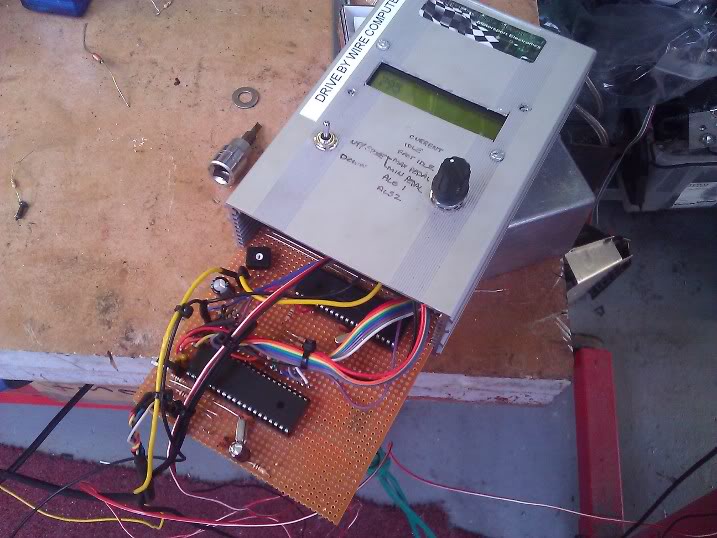
The final computer;
For my side business I also bought a cheap (if you can call it cheap) chinese CNC milling machine.. Initially its rubbish but after re-designing it, modifying it and replacing some parts its now very good.. Very accurate and reliable.. Ill be using it to isolation mill PCB, engrave and cut plastic for dash panels and to mill billet ali (very slowly, but still in house)
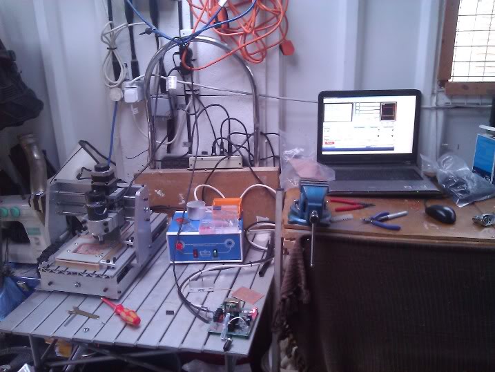
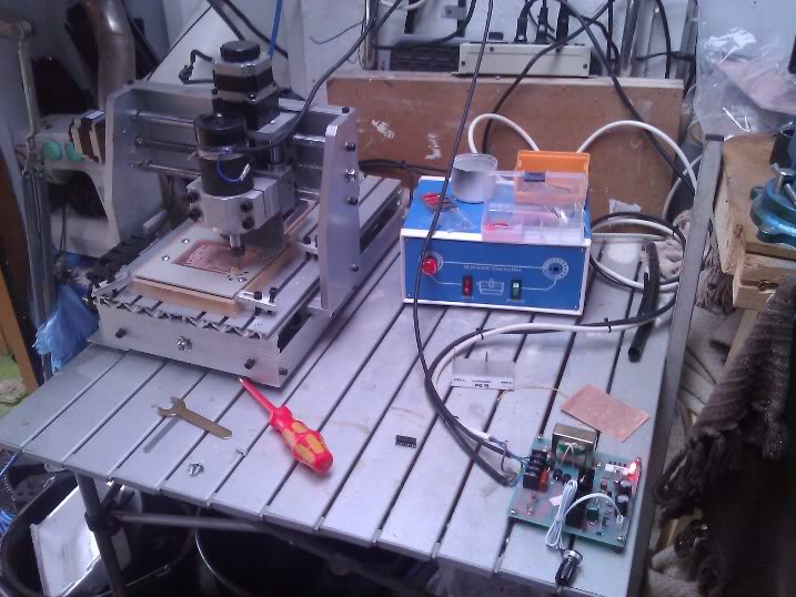
Here you can see the power supply board for the VFD (Variable Frequency Driver) for the spindle. I moved it out of the case as the amount of noise it was chucking out was stupid! Also, the spindle was manually controlled which was a bit stupid plus also didnt offer a decent indication of when it was finished the operation. I built a small daughter board to sit internally in-line with the parallel port which allows signals to be extracted / added. It has a couple of relays on and one of which drives the spindle motor VFD. It is now fully automated, the only thing i have to do is tool changes, but sticking my head out and listening for the noise is a good indicator of whether its finished or not..