2WD Cos - How to use ABS for a speed sensor output - a guide
 03-04-2006, 09:56 AM
#1
PassionFord Post Whore!!
Thread Starter

Join Date: Jun 2003
Location: Exeter
Posts: 3,744
Likes: 0
Received 0 Likes
on
0 Posts
Hi all,
After my experience in trying to get a digital pulsed speed output for a 2WD Cossie for my Blitz Boost Controller, I thought I would post the details so that all may benefit that may need it!
One brief initial warning - before getting involved with this, make sure that whatever you are using with the sensor output can be adequately calibrated! Otherwise, you may be wasting your time.
Background
For information, the L1 - 6 2WD Cosworth ECU's do not have a speed output. Many new gismos these days (from timers to boost controllers etc) require a pulsed vehicle speed sensor in order to operate fully. Modern cars such as the Subaru all take their speedo input from the ECU, and this is who they target their gadgets at! All is not lost however, as all ABS equipped cars are fitted with no less than four speed sensors. All you need to know is which wire to splice into!
Preparation
Firstly, make sure that your current wiring is in good condition. Providing the ABS fault light is not on, there is a good chance that the system is fully operational.
Make sure that you have all the necessary tools to do the job properly, if you leave exposed signal wire, dont come crying if it earths on something and screws either the sensor or the ABS brain.
ABS Brain Location
The ABS control ECU in the 2WD Cosworth is located above the main ECU in the top half of the passenger side of the dashboard, behind the infill panel. The easiest and safesty way to access it is to remove the main ECU and carefully set aside, and then remove the wiring loom harness from the ABS module. Trust me, this will give you more room to work!
Disassembly and wire connection
1) The wiring loom plug to the ABS is normally identified by a Green casing. First, remove the small rubber cover at one end of the plug, and then the outer plastic top will slide back. Keep an eye for two small black plastic infill pieces, which will almost certainly fall out!
2) Once you have exposed the wiring in the back of the plug, you will be able to see numbering adjacent to each of the wires. We are only interested in one of four of those wires.
3) Each Sensor is attached to the Module essentially by two wires - a signal wire, and a shield (earth) wire. For the connection to the speed pulse, we are only interested in the signal wire. DO NOT EARTH THE DEVICE THROUGH THE SHIELD WIRE. Likewise, dont take your main power pickup from this loom. Provide a separate power an earth to whatever you are connecting direct to battery or fuse box!
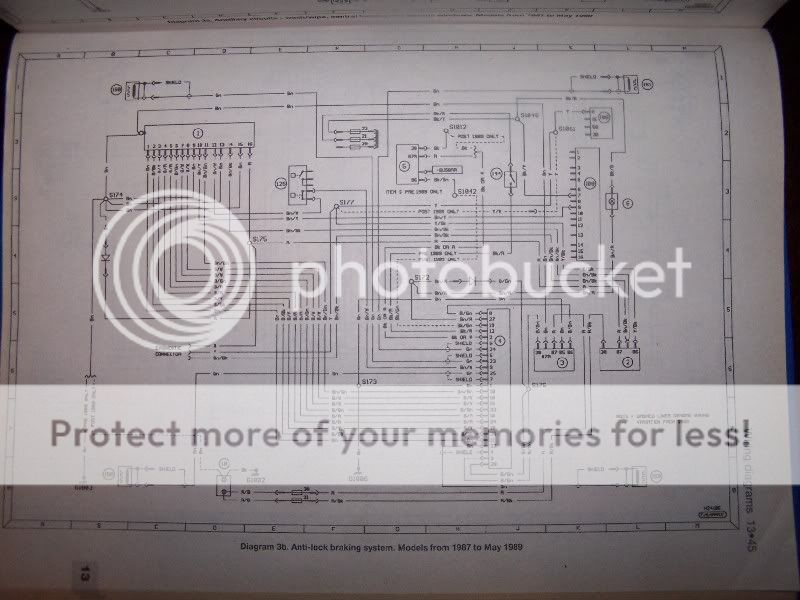
4)Because it is a Ford, the signal from each of the four wheels is helpfully exactly the same colour! (Green). This means that the only way to identify the right wheel is with the assistance of a schematic drawing (attached below)
5) The following represents identification of which wire does what....
Loom Pin no - Wheel - Sensor ID on Schematic
25 - Left Front - 158
22 - Left Rear - 159
23 - Right Front - 160
24 - Right Rear - 161
All of the above are the signal wires, and all are helpfully Green!
6) Free piece of advice! Unless you are wiring to something that directly controls fuelling, wire up to the front wheel. This will ensure that any wheel speed is not affected by wheel-spin!
7) By far the best way to splice into the cable is to trace it back a suitably distance away from the module, and crimp on using an appropriate adaptor. Make sure any exposed wiring is suitably shielded.
8) Once connected, carefully put everything back together.
Calibration
I HAVE ABSOLUTELY NO IDEA HOW MANY TEETH THERE ARE ON ONE OF THE WHEELS! Nor do intend to count them this side of death!
If you need to know, the easiest wheel to check is the front, and to be honest, the best time to do this is whilst changing a wheel bearing, as the abs wheel can be removed from the hub, and then you can count properly on a bench.
The Blitz Boost Controller allows you to self-calibrate, which requires you to drive at a pre-defined speed (25mph) and then press a button. Personally I believe that this is best done on the open road with a GPS. Most speedos have an inherant inaccuracy. If you are using devices that provide estimates of BHP, if you time your device to your Speedo, it will almost certainly mean that you are going slower than you thing, and therefore the BHP figures will come back better than they should be! Garbage in - garbage out!
All Done
Hey presto, you now have a proper speed output for whatever device you require.
I believe that the ABS sensors are used by RaceLogic when installing their traction control system.
The Pictures!
Below is the schematic for the ABS complete system. This is the same for all Sierras up to 1989. Also is the two pages of guidance notes that identify the sensors and modules etc!
They are from a well known brand of car manuals!


I hope that this helps at least one other person!
(Edited photo sizes to smaller)
JJ
After my experience in trying to get a digital pulsed speed output for a 2WD Cossie for my Blitz Boost Controller, I thought I would post the details so that all may benefit that may need it!
One brief initial warning - before getting involved with this, make sure that whatever you are using with the sensor output can be adequately calibrated! Otherwise, you may be wasting your time.
Background
For information, the L1 - 6 2WD Cosworth ECU's do not have a speed output. Many new gismos these days (from timers to boost controllers etc) require a pulsed vehicle speed sensor in order to operate fully. Modern cars such as the Subaru all take their speedo input from the ECU, and this is who they target their gadgets at! All is not lost however, as all ABS equipped cars are fitted with no less than four speed sensors. All you need to know is which wire to splice into!
Preparation
Firstly, make sure that your current wiring is in good condition. Providing the ABS fault light is not on, there is a good chance that the system is fully operational.
Make sure that you have all the necessary tools to do the job properly, if you leave exposed signal wire, dont come crying if it earths on something and screws either the sensor or the ABS brain.
ABS Brain Location
The ABS control ECU in the 2WD Cosworth is located above the main ECU in the top half of the passenger side of the dashboard, behind the infill panel. The easiest and safesty way to access it is to remove the main ECU and carefully set aside, and then remove the wiring loom harness from the ABS module. Trust me, this will give you more room to work!
Disassembly and wire connection
1) The wiring loom plug to the ABS is normally identified by a Green casing. First, remove the small rubber cover at one end of the plug, and then the outer plastic top will slide back. Keep an eye for two small black plastic infill pieces, which will almost certainly fall out!
2) Once you have exposed the wiring in the back of the plug, you will be able to see numbering adjacent to each of the wires. We are only interested in one of four of those wires.
3) Each Sensor is attached to the Module essentially by two wires - a signal wire, and a shield (earth) wire. For the connection to the speed pulse, we are only interested in the signal wire. DO NOT EARTH THE DEVICE THROUGH THE SHIELD WIRE. Likewise, dont take your main power pickup from this loom. Provide a separate power an earth to whatever you are connecting direct to battery or fuse box!
4)Because it is a Ford, the signal from each of the four wheels is helpfully exactly the same colour! (Green). This means that the only way to identify the right wheel is with the assistance of a schematic drawing (attached below)
5) The following represents identification of which wire does what....
Loom Pin no - Wheel - Sensor ID on Schematic
25 - Left Front - 158
22 - Left Rear - 159
23 - Right Front - 160
24 - Right Rear - 161
All of the above are the signal wires, and all are helpfully Green!
6) Free piece of advice! Unless you are wiring to something that directly controls fuelling, wire up to the front wheel. This will ensure that any wheel speed is not affected by wheel-spin!
7) By far the best way to splice into the cable is to trace it back a suitably distance away from the module, and crimp on using an appropriate adaptor. Make sure any exposed wiring is suitably shielded.
8) Once connected, carefully put everything back together.
Calibration
I HAVE ABSOLUTELY NO IDEA HOW MANY TEETH THERE ARE ON ONE OF THE WHEELS! Nor do intend to count them this side of death!
If you need to know, the easiest wheel to check is the front, and to be honest, the best time to do this is whilst changing a wheel bearing, as the abs wheel can be removed from the hub, and then you can count properly on a bench.
The Blitz Boost Controller allows you to self-calibrate, which requires you to drive at a pre-defined speed (25mph) and then press a button. Personally I believe that this is best done on the open road with a GPS. Most speedos have an inherant inaccuracy. If you are using devices that provide estimates of BHP, if you time your device to your Speedo, it will almost certainly mean that you are going slower than you thing, and therefore the BHP figures will come back better than they should be! Garbage in - garbage out!
All Done
Hey presto, you now have a proper speed output for whatever device you require.
I believe that the ABS sensors are used by RaceLogic when installing their traction control system.
The Pictures!
Below is the schematic for the ABS complete system. This is the same for all Sierras up to 1989. Also is the two pages of guidance notes that identify the sensors and modules etc!
They are from a well known brand of car manuals!
I hope that this helps at least one other person!
(Edited photo sizes to smaller)
JJ
 03-04-2006, 10:08 AM
#4
PassionFord Post Whore!!
iTrader: (9)
Join Date: May 2003
Location: Essex/Middlesex
Posts: 7,836
Likes: 0
Received 0 Likes
on
0 Posts
nice info
just to add this will only work on a device that has a self calibrating input speed signal.
For something like the ACVR etc you would need to the pulse to be correct initially (I have heard of people using resistors to divide/multiply the signal)
doh! just checked your post again and you DID actually mention that
 still i have heard of some people using other stuff with out the self calibrating feature with the pulse dived/mulitplied so might be an option
also
i would have though the best way would be to strip the sheeth back on the wire exposing the wire then soilder the other wire onto that and cover with heatshrink.
just to add this will only work on a device that has a self calibrating input speed signal.
For something like the ACVR etc you would need to the pulse to be correct initially (I have heard of people using resistors to divide/multiply the signal)
doh! just checked your post again and you DID actually mention that
still i have heard of some people using other stuff with out the self calibrating feature with the pulse dived/mulitplied so might be an option also
7) By far the best way to splice into the cable is to trace it back a suitably distance away from the module, and crimp on using an appropriate adaptor. Make sure any exposed wiring is suitably shielded.


 03-04-2006, 10:29 AM
#7
PassionFord Post Whore!!
Thread Starter
Join Date: Jun 2003
Location: Exeter
Posts: 3,744
Likes: 0
Received 0 Likes
on
0 Posts
Cheers All for kind words 
Thanks Stu, I am happy for it to be moved over - hope it benefits all that need help with it!
I would agree with the above, this is definately the preferred option. However, if you are not comfortable soldering joint in like this, there are plastic clips available that can be crimped on, which are sometimes preferred by those less experienced with elecs 
Cheers
JJ
Thanks Stu, I am happy for it to be moved over - hope it benefits all that need help with it!
Quote:
7) By far the best way to splice into the cable is to trace it back a suitably distance away from the module, and crimp on using an appropriate adaptor. Make sure any exposed wiring is suitably shielded.
i would have though the best way would be to strip the sheeth back on the wire exposing the wire then soilder the other wire onto that and cover with heatshrink.
_________________
Cheers
JJ
Trending Topics
03-04-2006, 11:16 AM
#8
PassionFord Post Whore!!
Thread Starter
Join Date: Jun 2003
Location: Exeter
Posts: 3,744
Likes: 0
Received 0 Likes
on
0 Posts
Just a quick note,
I have amended the photographs to a smaller size so that the article can be read a little easier.
If you want an enlarged version, mail me and I will send the full size versions. Warning though, each photo is about 500KB
JJ
I have amended the photographs to a smaller size so that the article can be read a little easier.
If you want an enlarged version, mail me and I will send the full size versions. Warning though, each photo is about 500KB
JJ
03-04-2006, 11:56 AM
#11
PassionFord Post Whore!!

Join Date: May 2003
Location: Wiltshire UK
Posts: 3,795
Likes: 0
Received 0 Likes
on
0 Posts
nice description 
also worth emphasising that the sensors are wired using shielded cable all the way into the ECU connector, so you will need to carefully cut through the jacket, and screen to be able to expose the core which carries the signal - make absolutely sure that no wire whiskers from the screen manage to short to the signal core connection.
Alternatively if you are nimble with the right soldering equipment, you can solder the wire to the back of the crimp terminal in the ECU connector without disturbing the cable screen
Also the signal that you get straight off the sensor is an analog waveform that varies in amplitude with speed, the device you connect to possibly may not be happy with that if it's expecting a nice clean digital type squarewave signal.. conversely there is also the possibility of the external device clamping the signal from the sensor and upsetting the ABS system..
These are only possibilities, not neccesarily likely, but worth bearing in mind..
03-04-2006, 12:04 PM
#12
PassionFord Post Whore!!

Join Date: May 2003
Location: Essex
Posts: 4,091
Likes: 0
Received 0 Likes
on
0 Posts
Originally Posted by JjCoDeX75
I HAVE ABSOLUTELY NO IDEA HOW MANY TEETH THERE ARE ON ONE OF THE WHEELS! Nor do intend to count them this side of death!
03-04-2006, 01:10 PM
#13
PassionFord Post Whore!!
Thread Starter
Join Date: Jun 2003
Location: Exeter
Posts: 3,744
Likes: 0
Received 0 Likes
on
0 Posts
Originally Posted by richm
nice description
also worth emphasising that the sensors are wired using shielded cable all the way into the ECU connector, so you will need to carefully cut through the jacket, and screen to be able to expose the core which carries the signal - make absolutely sure that no wire whiskers from the screen manage to short to the signal core connection.
Alternatively if you are nimble with the right soldering equipment, you can solder the wire to the back of the crimp terminal in the ECU connector without disturbing the cable screen
Also the signal that you get straight off the sensor is an analog waveform that varies in amplitude with speed, the device you connect to possibly may not be happy with that if it's expecting a nice clean digital type squarewave signal.. conversely there is also the possibility of the external device clamping the signal from the sensor and upsetting the ABS system..
These are only possibilities, not neccesarily likely, but worth bearing in mind..

On the matter of the shielding, you are absolutely right, likewise on the analogue signal, rather than digital. Sorry if my original article misleads. That said, most devices are looking for a pulse, and the analogue wave provides this, in a slightly less "on-off" way.
On the ABS inteference, I can only talk from my own experience, and am happy to confirm that it has had no adverse effect on my ABS.
Cheers
JJ
03-04-2006, 01:34 PM
#14
PassionFord Post Whore!!
Join Date: May 2003
Location: Wiltshire UK
Posts: 3,795
Likes: 0
Received 0 Likes
on
0 Posts
Not misleading at all! Just that for someone starting afresh it's nice to be aware of what they'll come across not everyone has come across the screened cable situation like this to be familiar with the issues maybe..
I fitted a Racelogic TC system for someone a while back, so have got the benefit of knowing exactly what it's like in there, as you do!
I fitted a Racelogic TC system for someone a while back, so have got the benefit of knowing exactly what it's like in there, as you do!
 04-04-2006, 07:46 AM
#18
PassionFord Post Whore!!
Join Date: May 2003
Location: Wiltshire UK
Posts: 3,795
Likes: 0
Received 0 Likes
on
0 Posts
Originally Posted by JjCoDeX75
Cool - How do you find the race-logic system? I have thought about it, but cant quite get round to getting one!
I fitted a system for Fast Road and Track magazine a couple of years ago, onto their stg3 2wd Sapph, so i didn't get a lot of time experiencing the results.. but yes, it all seemed to work as described with no drama
08-04-2006, 09:26 AM
#21
Advanced PassionFord User

Join Date: Sep 2003
Location: Shropshirsestashire
Posts: 2,239
Likes: 0
Received 0 Likes
on
0 Posts
JJ Im gonna be tackling this over the next few weeks on my esco's track car as we disscussed.
Do you Know if the APEXI RSM would support this set up ? as that is what im looking at fitting ?.
Nice essay by the way
Regards Doug.
Do you Know if the APEXI RSM would support this set up ? as that is what im looking at fitting ?.
Nice essay by the way
Regards Doug.
08-04-2006, 03:00 PM
#22
PassionFord Post Whore!!
Thread Starter
Join Date: Jun 2003
Location: Exeter
Posts: 3,744
Likes: 0
Received 0 Likes
on
0 Posts
Hi Doug
I have read through the manual for the Apexi RSM, and to be honest, it doesnt seem to have a self-calibration mode. This unit relys on the fact that the majority of Japanese cars send speed pulse in one of three different ways.
THat said, it does have correction for wheel size and for different pulses. I suspect that one of the three settings would not be the same as the cossie.
If this is the case, you might want to consider the Blitz equivalent ( I think its called the Powermeter ID) which I know supports self calibration - I will check this as I have a manual for it somewhere
If you have already bought it, then try it - you never know!!
By the way, manual for Apexi in english below:
http://www.apexi-usa.com/pdfInstallation/14.pdf
Cheers
JJ
Cheers
JJ
 08-04-2006, 05:09 PM
#24
PassionFord Post Whore!!
Thread Starter
Join Date: Jun 2003
Location: Exeter
Posts: 3,744
Likes: 0
Received 0 Likes
on
0 Posts
Bastards!!
I bought an In car VGA touchscreen for the car, and it arrived totally f**ked!
It has cost me 70 quid to post it back to hong kong!!!!! So far, still no screen, but fingers crossed I'll have one soon.
What annoys me is that I thought it wasnt available from the UK. You can imagine my irritation when I found a UK trader selling one for just �30 more than I paid....... DOH!
When the Apexi arrives, (if it arrives) give it a try, you never know! I have a feeling that the ABS sensor has too many pick-ups for the standard settings.
Cheers m8
JJ
25-07-2006, 07:11 AM
#27
PassionFord Post Troll

Join Date: Jul 2003
Location: Suffolk
Posts: 2,582
Likes: 0
Received 0 Likes
on
0 Posts
I believe that the ABS sensors are used by RaceLogic when installing their traction control system.
Good write up
26-07-2006, 09:14 PM
#29
PassionFord Post Troll
Join Date: Jul 2003
Location: Suffolk
Posts: 2,582
Likes: 0
Received 0 Likes
on
0 Posts
Originally Posted by JjCoDeX75
TRaction control in a Cos Rush ( i am guessing DAX?) has to be an absolute must!!! LOL
JJ
JJ
needed the money
28-07-2006, 05:46 PM
#30
PassionFord Post Whore!!
Thread Starter
Join Date: Jun 2003
Location: Exeter
Posts: 3,744
Likes: 0
Received 0 Likes
on
0 Posts
Originally Posted by CosRush
Originally Posted by JjCoDeX75
TRaction control in a Cos Rush ( i am guessing DAX?) has to be an absolute must!!! LOL
JJ
JJ
needed the money

Thread
Thread Starter
Forum
Replies
Last Post
FlashRS
Ford RS Cosworth Parts for Sale
13
31-08-2015 06:02 PM