Building a custom inlet manifold for YB
 02-11-2013, 12:27 PM
#1
Too many posts.. I need a life!!
Thread Starter

Hello!
Thought I´d share this project I am working on. It started with me wanting to get better at 3d-modelling and to try and use the tools I have learned so far. I am currently on my last year of MSc mechanical engineering studies so I am lucky to have access to several different laboratories to do the work
Also this thread has been inspiring me to realise this project:
http://forums.hybridz.org/topic/6154...intake-plenum/
I have been doing the engine package design for our universitys Formula Student-team for a couple of years and so I have made a complete model of the YB engine in an engine simulation software called GT-Suite. All dimensions such as runner length, runner area, plenum volume etc have been calculated through this software and implemented in the 3d-model.
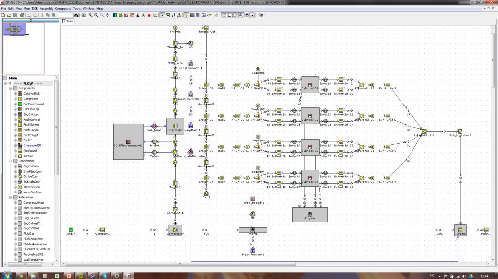
To verify functionality I have done finite element analysis of the complete structure as well as CFD simulations.
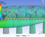
The boundary conditions on this simulation was wrong, the inlet velocity shown is over 110m/s, as opposed to 50m/s in reality. I have done more accurate simulations, but I do not have any picture of it. Might do the simulation again and upload some better results
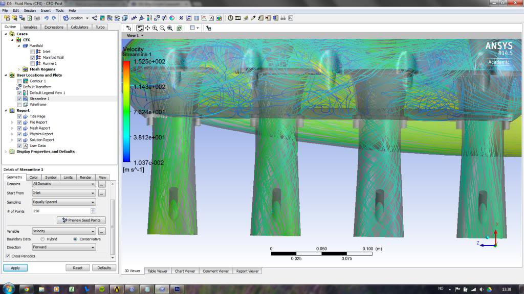
Swirl / turbulens at 2 and 3 as a result of too high inlet velocity
Did a quick video showing steady state result:
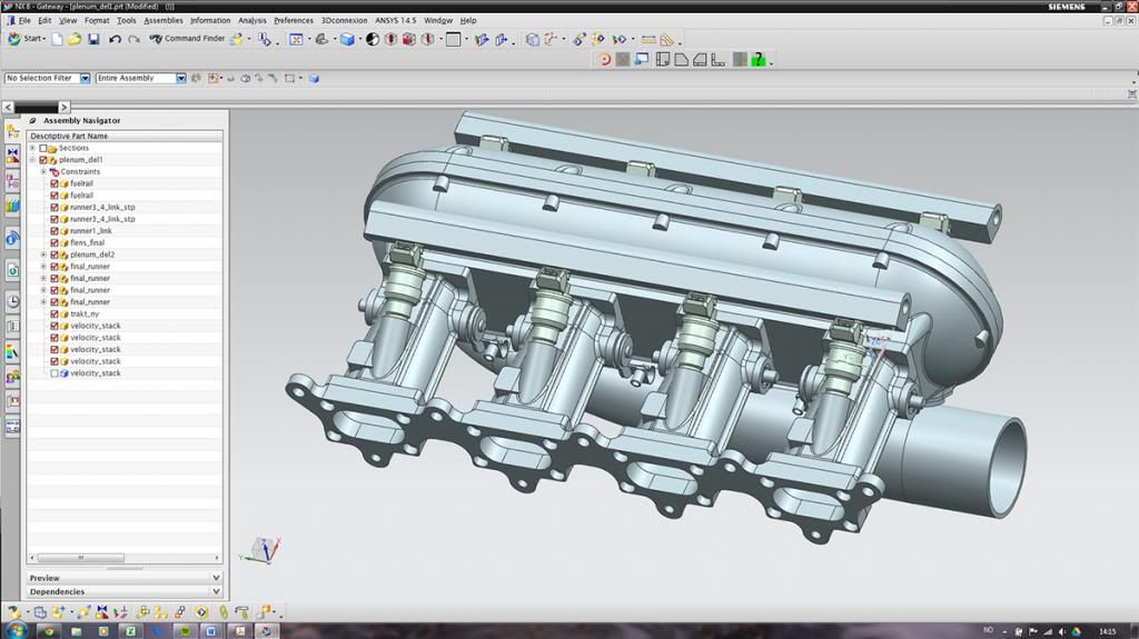
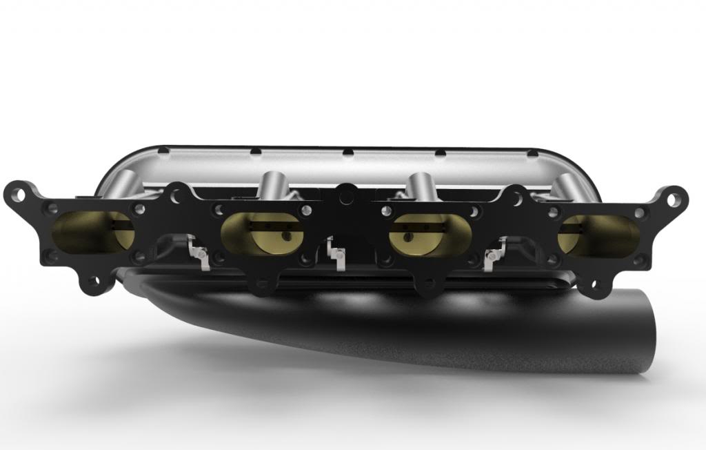
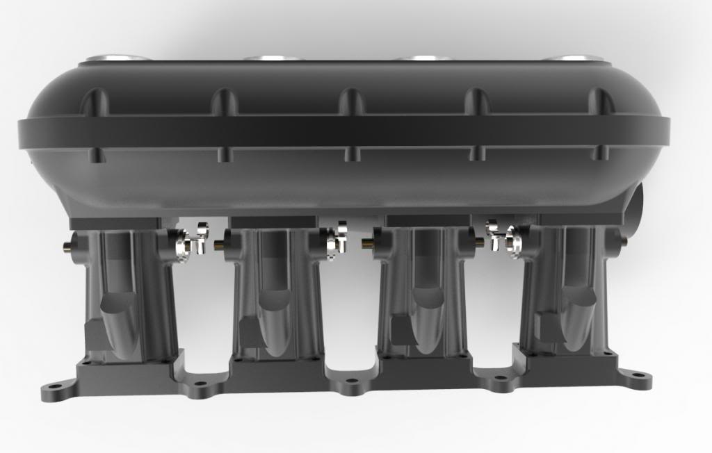
Some pic of the model. They are a bit random as I have been working on this for the last 6 months, designing and re-designing.. Ended up with a MIS / Jenvey hybrid design.
I will do some new renderings soon. It is actually only partly complete in these pictures
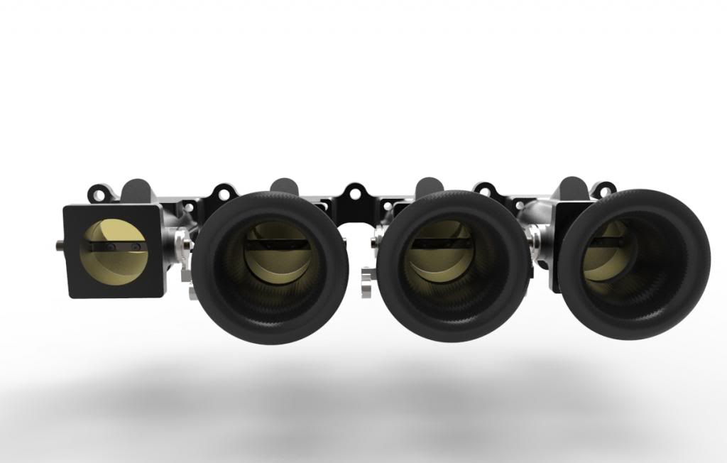

The velocity stacks will be made out of carbon fiber in a small autoclave we have down in the fatigue lab. An autoclave is a pressurized and high temp chamber. In combination with pre impregnated (prepreg) carbon fiber cloth one can produce components with perfect shape on both sides:

Fun part begins
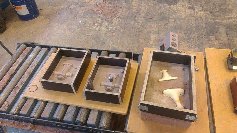
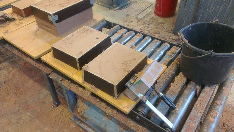
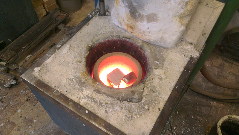
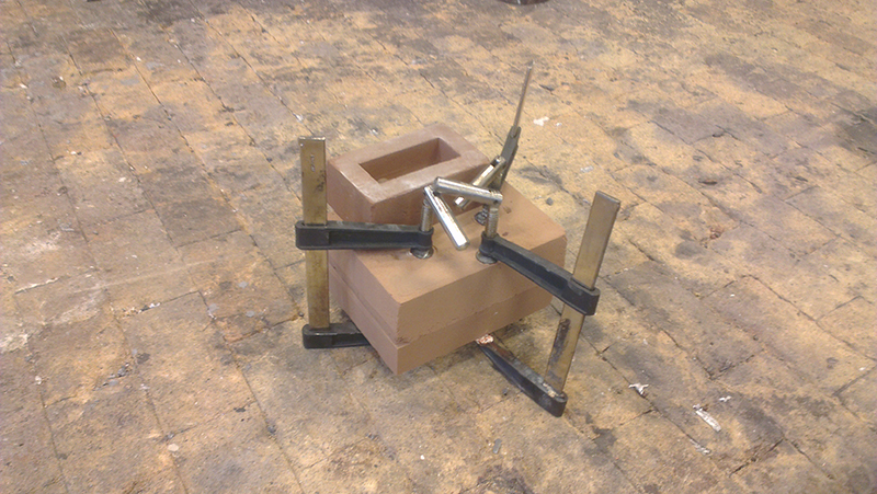
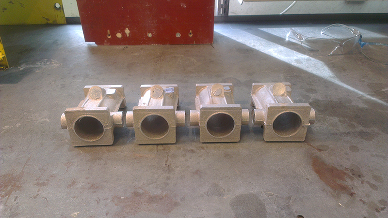
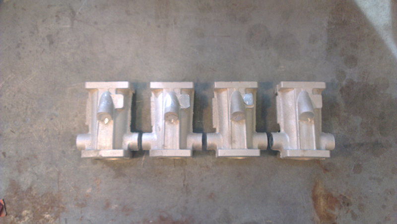
First prototype
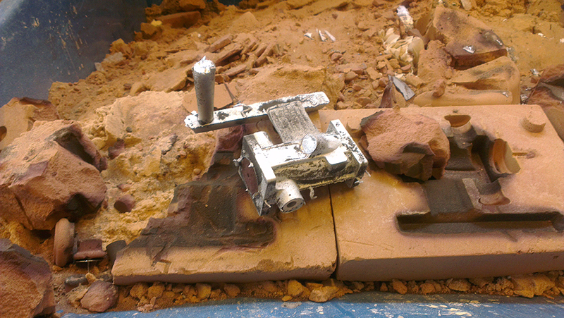
4 more times as the first one had some casting inconsistency
Will of course go over these by hand to remove the casting marks etc
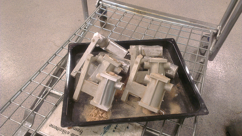
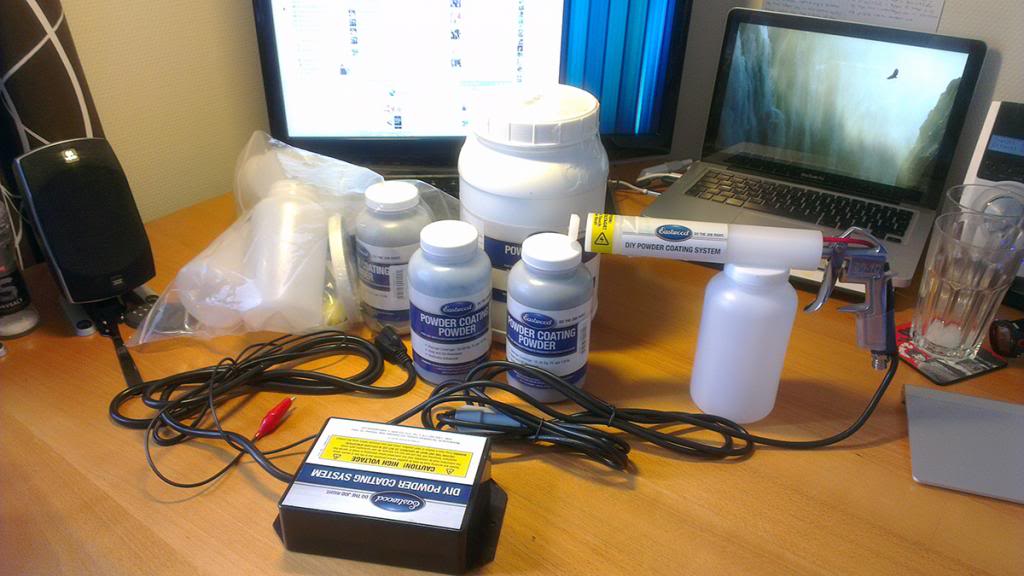
I wanted to paint this inlet black so I purchased powder coating equipment. First I tried anodizing the casting, but the high silicon content (7% silicon, the alloy is AlSi7) did not give desired result.
PC equipment;
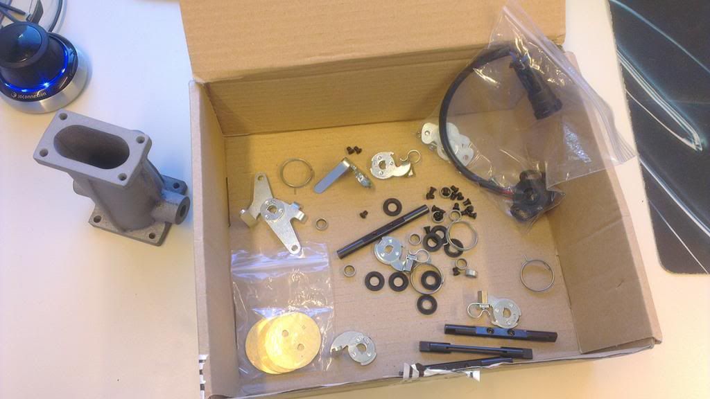
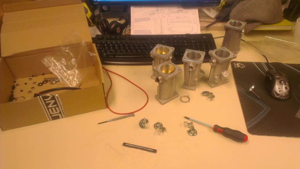
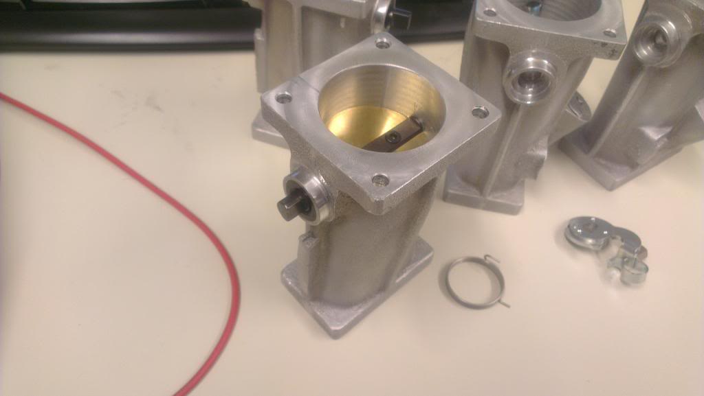
Failed anodizing on the part seen on the left (first prototype used for testing. should have turned out colored black). Also bought seals, bearings, shafts, return springs, throttle plates and complete linkage etc from Jenvey Dynamics. They normally dont sell these parts, but as I am a student they decided to help me out!
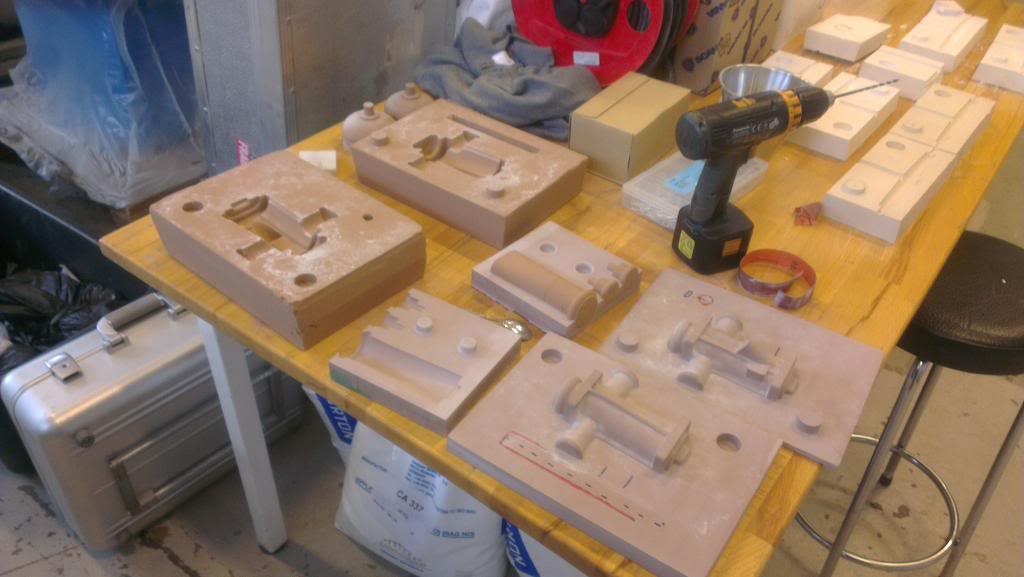
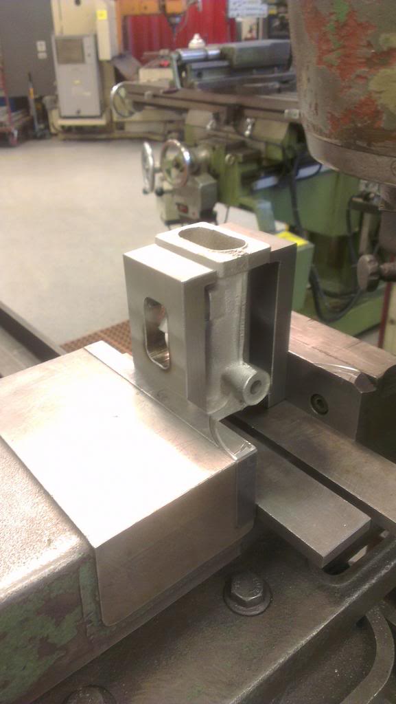
The drag angles required for traditional sand casting made the runners hard to fix in a vice during machining, so had to make a simple jig for them. This way I can machine every runner exactly the same way. Im a novice at machining, but trying my best

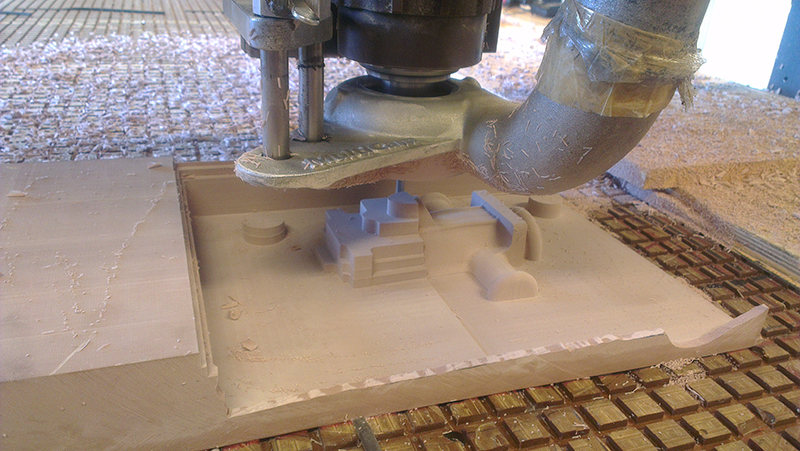
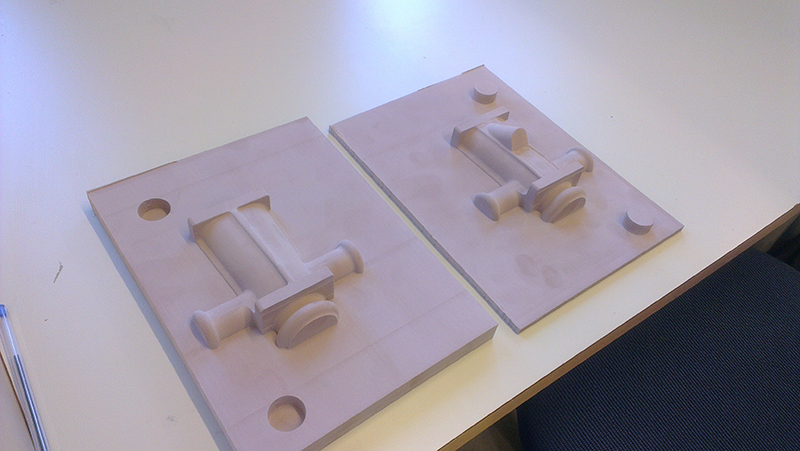
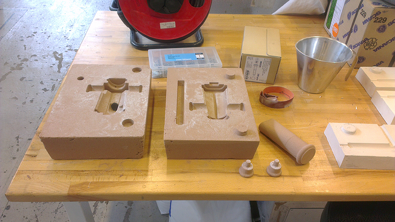
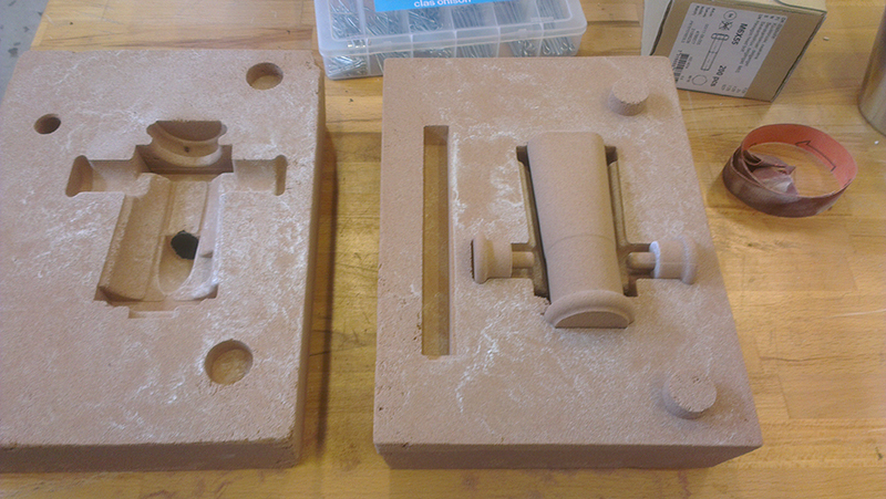
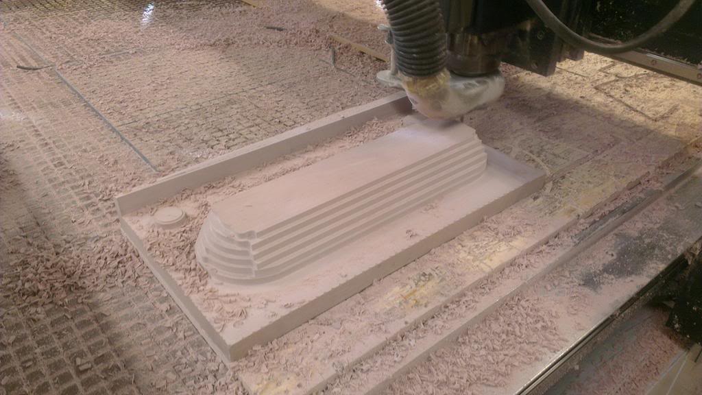
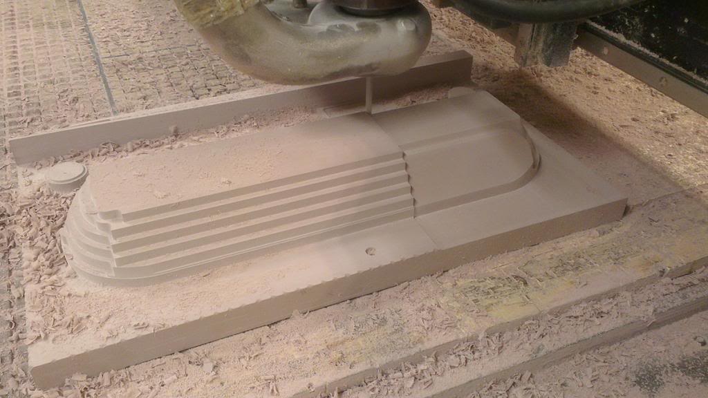
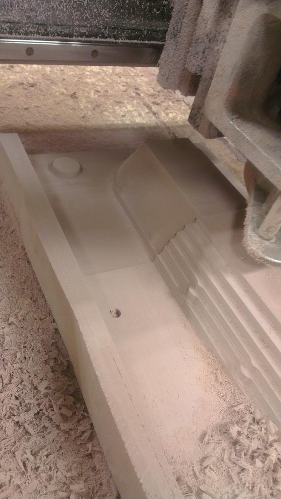
This last week I have been macnining the molds for the two main plenum covers. The inlet tube will be a Jenvey-style bolt on part, and I have some work left on it before it is ready for machining.
Hopefully I will finish the inlet tube (or whatever you call it) in a couple of weeks
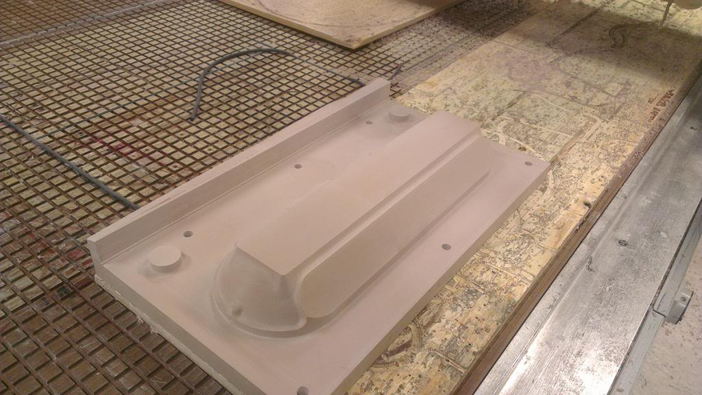
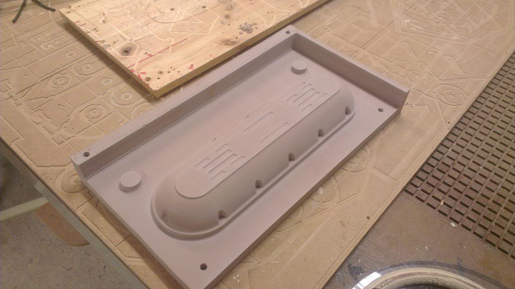
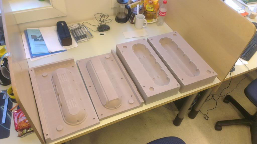
Will be back with more pictures as I machine the parts and sand cast the plenum
Andreas
Thought I´d share this project I am working on. It started with me wanting to get better at 3d-modelling and to try and use the tools I have learned so far. I am currently on my last year of MSc mechanical engineering studies so I am lucky to have access to several different laboratories to do the work
Also this thread has been inspiring me to realise this project:
http://forums.hybridz.org/topic/6154...intake-plenum/
I have been doing the engine package design for our universitys Formula Student-team for a couple of years and so I have made a complete model of the YB engine in an engine simulation software called GT-Suite. All dimensions such as runner length, runner area, plenum volume etc have been calculated through this software and implemented in the 3d-model.
To verify functionality I have done finite element analysis of the complete structure as well as CFD simulations.
The boundary conditions on this simulation was wrong, the inlet velocity shown is over 110m/s, as opposed to 50m/s in reality. I have done more accurate simulations, but I do not have any picture of it. Might do the simulation again and upload some better results
Swirl / turbulens at 2 and 3 as a result of too high inlet velocity
Did a quick video showing steady state result:
Some pic of the model. They are a bit random as I have been working on this for the last 6 months, designing and re-designing.. Ended up with a MIS / Jenvey hybrid design.
I will do some new renderings soon. It is actually only partly complete in these pictures
The velocity stacks will be made out of carbon fiber in a small autoclave we have down in the fatigue lab. An autoclave is a pressurized and high temp chamber. In combination with pre impregnated (prepreg) carbon fiber cloth one can produce components with perfect shape on both sides:
Fun part begins
First prototype
4 more times as the first one had some casting inconsistency
Will of course go over these by hand to remove the casting marks etc
I wanted to paint this inlet black so I purchased powder coating equipment. First I tried anodizing the casting, but the high silicon content (7% silicon, the alloy is AlSi7) did not give desired result.
PC equipment;
Failed anodizing on the part seen on the left (first prototype used for testing. should have turned out colored black). Also bought seals, bearings, shafts, return springs, throttle plates and complete linkage etc from Jenvey Dynamics. They normally dont sell these parts, but as I am a student they decided to help me out!
The drag angles required for traditional sand casting made the runners hard to fix in a vice during machining, so had to make a simple jig for them. This way I can machine every runner exactly the same way. Im a novice at machining, but trying my best
This last week I have been macnining the molds for the two main plenum covers. The inlet tube will be a Jenvey-style bolt on part, and I have some work left on it before it is ready for machining.
Hopefully I will finish the inlet tube (or whatever you call it) in a couple of weeks
Will be back with more pictures as I machine the parts and sand cast the plenum
Andreas
Last edited by nixon_2wd; 02-11-2013 at 12:36 PM.

The following users liked this post:
_Jimmy_ (12-12-2018)
 02-11-2013, 01:04 PM
#4
Ben

Without doubt the coolest thing I've seen for a while.

 truly awsome
Trending Topics
02-11-2013, 04:32 PM
#11
Too many posts.. I need a life!!
Thread Starter
Thank you for your interest! I have been thinking of this project constantly since April, so its very cool finally seeing it taking shape
02-11-2013, 07:02 PM
#16
Advanced PassionFord User

Amazing skills. Fancy doing a zetec turbo one?
02-11-2013, 07:25 PM
#17
Too many posts.. I need a life!!
Thread Starter
 02-11-2013, 07:32 PM
#18
Advanced PassionFord User
Shame you can't make a few. I reckon you would have orders

 02-11-2013, 09:03 PM
#21
Too many posts.. I need a life!!
Thread Starter
Thanks mate!
It is a very special feeling seeing the raw castings every time. Suddenly Im holding something Ive made from scratch
Haha I just need my own 3 axis CNC 
Last edited by nixon_2wd; 02-11-2013 at 09:08 PM.
 03-11-2013, 12:37 PM
#25
Too many posts.. I need a life!!
Thread Starter
Hi, no. Once the molds are ready the sand and casting itself is dirt cheap. Its the pre and post machining that is expensive. Luckily I get all this for free, even the casting material.
Hehe thanks mate
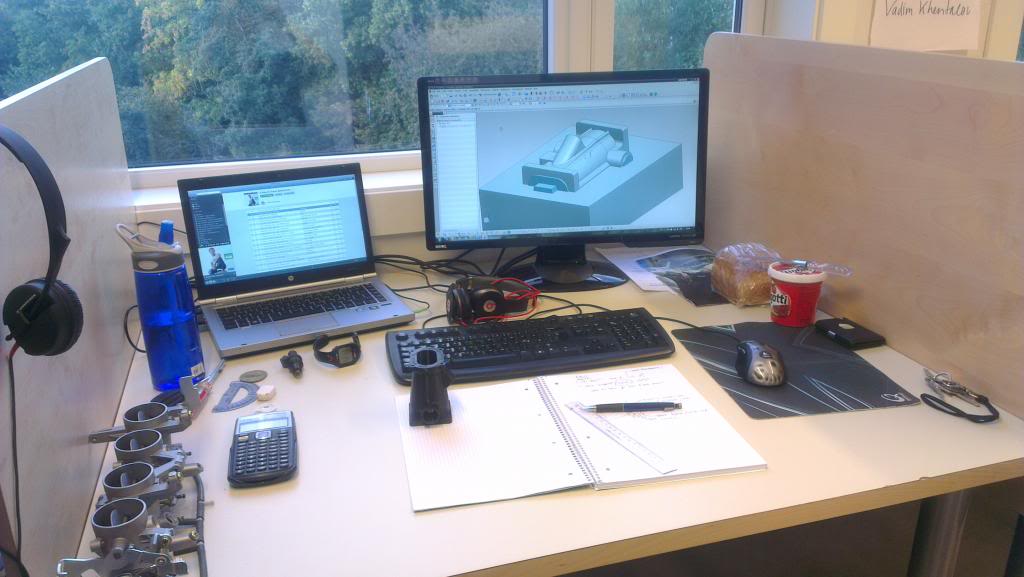
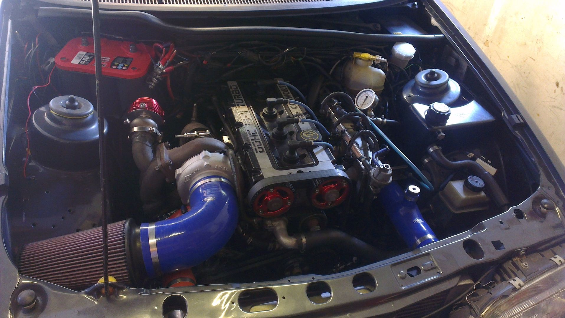
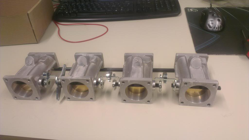
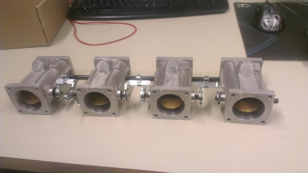
Heres a picture of my testing rig;
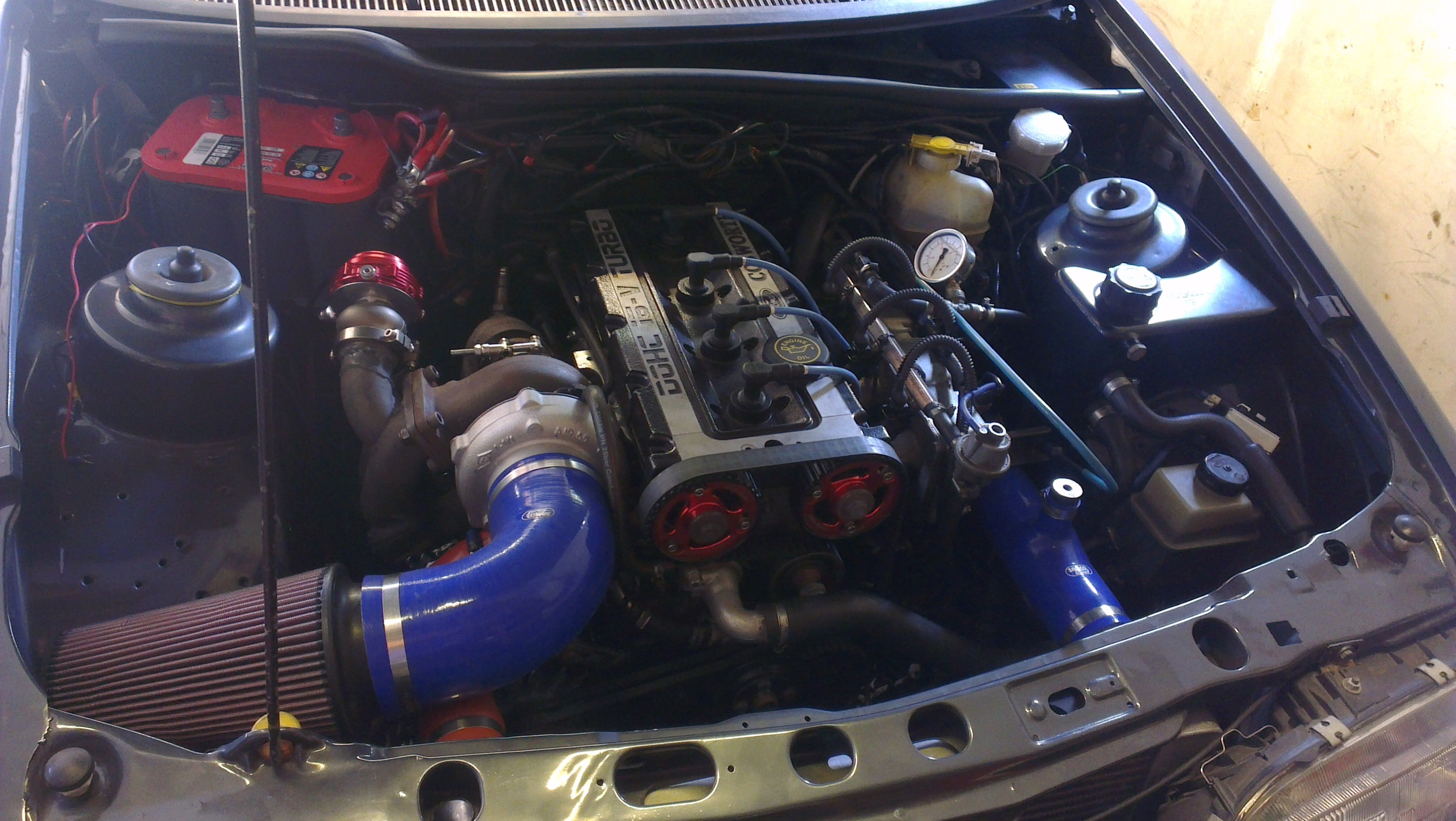
Heres a picture of my testing rig;
Last edited by nixon_2wd; 03-11-2013 at 12:49 PM.
 03-11-2013, 01:07 PM
#27
Too many posts.. I need a life!!
Thread Starter
Yeah  Actually I will have to modify the PAS reservoir as the new inlet will collide
Also currently modifying the standard pedal box as I want more adjustment on the hydraulic clutch. Going to be mounting the master cylinder inside of the car rather than on the bulk head as it is now. Im not able to move it around for adjustment, as place is too tight !
Actually I will have to modify the PAS reservoir as the new inlet will collide Also currently modifying the standard pedal box as I want more adjustment on the hydraulic clutch. Going to be mounting the master cylinder inside of the car rather than on the bulk head as it is now. Im not able to move it around for adjustment, as place is too tight !
03-11-2013, 02:43 PM
#30

Yeah Actually I will have to modify the PAS reservoir as the new inlet will collide
Also currently modifying the standard pedal box as I want more adjustment on the hydraulic clutch. Going to be mounting the master cylinder inside of the car rather than on the bulk head as it is now. Im not able to move it around for adjustment, as place is too tight !
Actually I will have to modify the PAS reservoir as the new inlet will collide Also currently modifying the standard pedal box as I want more adjustment on the hydraulic clutch. Going to be mounting the master cylinder inside of the car rather than on the bulk head as it is now. Im not able to move it around for adjustment, as place is too tight !


 31-01-2014, 06:20 PM
#34
Too many posts.. I need a life!!
Thread Starter
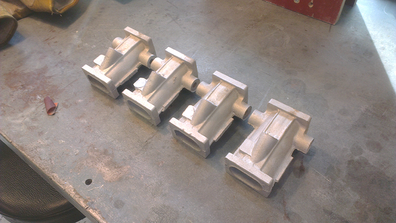
Hi guys, its going slow but managed to do some more work the last month. The runners are now almost completely finished. Just need to machine a hole for the idle screw on one of them, then finish them by hand.
Finished the design on the entry/lower plenum, Jenvey-style
Casting is a bit delayed but hopefully within the next few weeks.


The runners
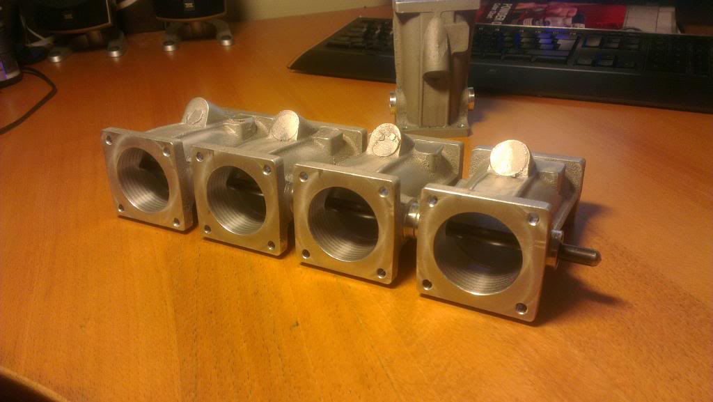
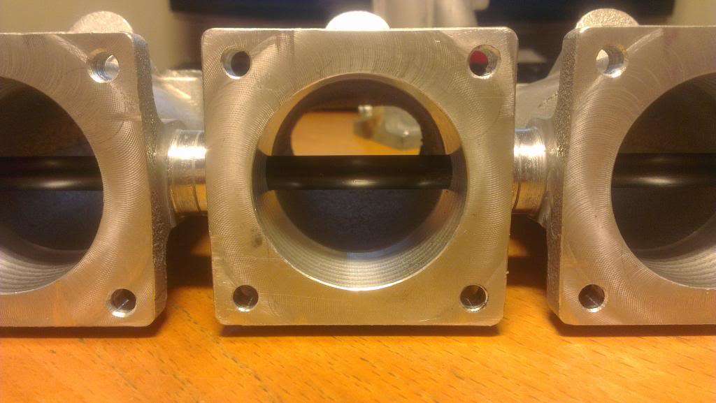
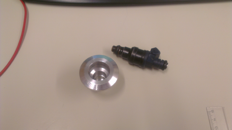
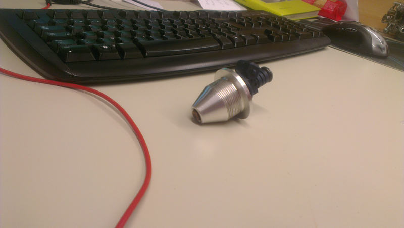
Sandblasted (very very find sand used) and finished machining the injector sockets and engine side flange
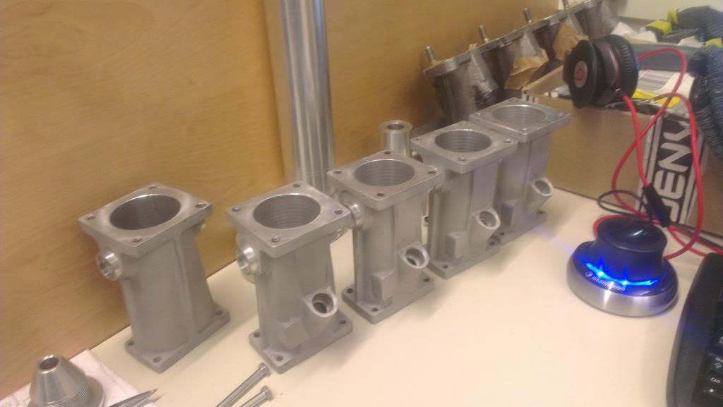
Made some injector sockets
Thats it for now. Also ordered three lengths of fuel rail stock from RMR. Will have to machine the sockets but at $80 inc shipping waaaay cheaper than finished items at Ł100 each!!
Will only be this prototype for now as it is taking some serious amount of time producing it.
Finished the design on the entry/lower plenum, Jenvey-style
Casting is a bit delayed but hopefully within the next few weeks.
The runners
Sandblasted (very very find sand used) and finished machining the injector sockets and engine side flange
Made some injector sockets
Thats it for now. Also ordered three lengths of fuel rail stock from RMR. Will have to machine the sockets but at $80 inc shipping waaaay cheaper than finished items at Ł100 each!!
Will only be this prototype for now as it is taking some serious amount of time producing it.
Last edited by nixon_2wd; 31-01-2014 at 06:29 PM.


 01-02-2014, 12:11 PM
#40
10K+ Poster!!


Lovely work....good to see engineering skills like this still being taught....you are the future!